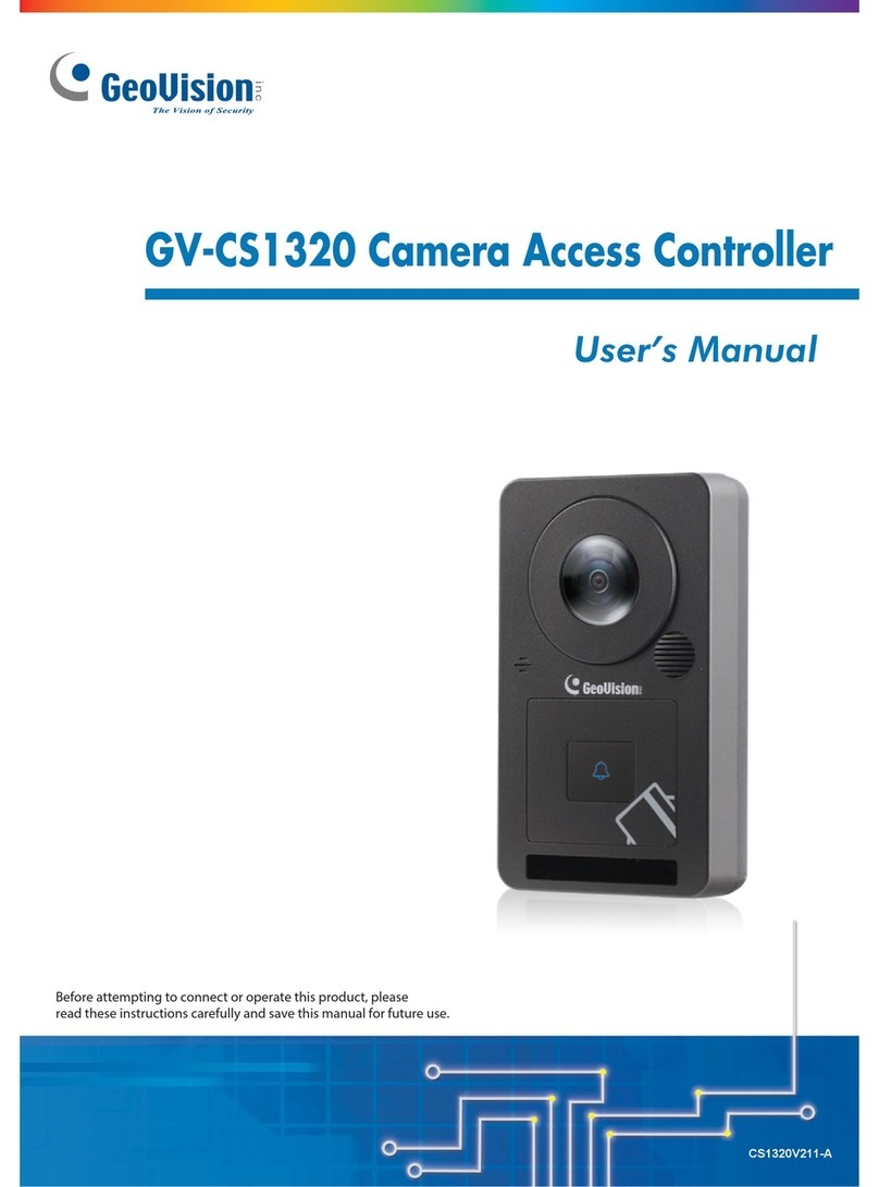
GeoVision GV-CS1320 User manual

GV-CS1320 Camera Access Controller
Before attempting to connect or operate this product, please
read these instructions carefully and save this manual for future use.
User’s Manual
CS1320V302-A

© 2019GeoVision, Inc. All rights reserved.
Under the copyright laws, thismanual may not be copied, inwhole or inpart,
without the written consent of GeoVision.
Every effort has been made to ensure that the information in this manual is
accurate. GeoVision, Inc. makes no expressed or implied warranty of any kind
and assumes no responsibility for errors or omissions. No liability is assumed
for incidental or consequential damages arising from the use of the information
or products contained herein. Features and specifications are subject to
change without notice.
GeoVision, Inc.
9F, No. 246, Sec. 1, Neihu Rd.,
Neihu District, Taipei, Taiwan
Tel: +886-2-8797-8377
Fax: +886-2-8797-8335
http://www.geovision.com.tw
Trademarks used in this manual: GeoVision, the GeoVision logo and GV
series products are trademarks of GeoVision, Inc. Windows is the registered
trademark of Microsoft Corporation.
November 2019

Contents
Naming and Definition ...........................................................vii
Optional Device ......................................................................vii
Installation Considerations ....................................................ix
Chapter 1 Introduction ..........................................................1
1.1 Key Features ............................................................................................................4
1.2 Packing List ..............................................................................................................5
1.3 System Requirements ..............................................................................................6
1.4 Physical Description .................................................................................................8
1.5 Installation ................................................................................................................9
1.5.1 Wire Definition..............................................................................................9
1.5.2 Installing GV-CS1320.................................................................................10
1.5.3 Replacing the Silica Gel Bag......................................................................11
1.6 Connecting GV-CS1320 .........................................................................................12
1.6.1 Connecting RS485 Readers ......................................................................12
1.6.2 Connecting Network Readers ....................................................................13
1.6.3 Connecting Input Devices to GV-CS1320..................................................13
1.6.4 Connecting an Output Device to GV-CS1320............................................14
1.6.5 Connecting GV-CS1320 to PC...................................................................15
1.6.6 Connecting the Power................................................................................17
1.7 LED Status and Beeper..........................................................................................18
Chapter 2 Getting Started ...................................................19
2.1 Creating Login Credential.......................................................................................20
2.1 Checking the Dynamic IP Address .........................................................................21
2.3 Assigning an IP Address ........................................................................................21
Chapter 3 Accessing the Camera Access Controller.......23
3.1 Accessing Your Surveillance Images .....................................................................23
3.2 Functions Featured on the Main Page ...................................................................25
3.2.1 The Live View Window...............................................................................25
3.2.2 The Control Panel of the Live View Window ..............................................27
iii

3.2.3 Snapshot of a Live Video ...........................................................................30
3.2.4 Video Recording.........................................................................................30
3.2.5 Digital PTZ .................................................................................................30
3.2.6 Wide Angle Lens Dewarping......................................................................31
3.2.7 Picture-in-Picture and Picture-and-Picture View ........................................32
3.2.8 Alarm Notification .......................................................................................34
3.2.9 Video and Audio Configuration ..................................................................35
3.2.10 Remote Configuration ..............................................................................36
3.2.11 Camera Name Display .............................................................................36
3.2.12 Image Enhancement ................................................................................36
Chapter 4 Administrator Mode ...........................................37
4.1 Video ......................................................................................................................38
4.1.1 Video Settings ............................................................................................39
4.1.2 Text Overlay...............................................................................................43
4.2 Access Control .......................................................................................................44
4.2.1 Basic Setting ..............................................................................................44
4.2.2 Extended Device ........................................................................................52
4.3 Events and Alerts ...................................................................................................54
4.3.1 RTSP/ONVIF..............................................................................................54
4.4 Network ..................................................................................................................55
4.4.1 Status .........................................................................................................55
4.4.2 LAN ............................................................................................................56
4.4.3 Advanced TCP/IP.......................................................................................57
4.4.4 IP Filtering ..................................................................................................60
4.4.5 SNMP Setting.............................................................................................61
4.5 Management...........................................................................................................62
4.5.1 Date and Time Setting ...............................................................................62
4.5.2 Storage Setting ..........................................................................................63
4.5.3 User Account..............................................................................................64
4.5.4 Log Information ..........................................................................................64
4.5.5 Tools ..........................................................................................................65
4.5.6 Language ...................................................................................................66
4.6 SIP .........................................................................................................................67
Chapter 5 Advanced Applications .....................................69
5.1 Upgrading System Firmware ..................................................................................69
iv
v
5.1.1 Using the Web Interface.............................................................................70
5.1.2 Using the IP Device Utility..........................................................................71
5.2 Backing Up and Restoring Settings........................................................................72
5.2.1 Backing Up the Settings.............................................................................72
5.2.2 Restoring the Settings................................................................................73
5.3 Restoring to Factory Default Settings.....................................................................74
5.4 Verifying Watermark ...............................................................................................75
5.4.1 Accessing AVI Files ...................................................................................75
5.4.2 Running Watermark Proof..........................................................................75
5.4.3 The Watermark Proof Window ...................................................................76
Chapter 6 GV-DVR / NVR / VMS Configurations ...............77
6.1 Setting up GV-CS1320 on GV-DVR / NVR ............................................................78
6.1.1 Customizing the Basic Settings..................................................................80
6.2 Setting up GV-CS1320 on GV-VMS.......................................................................82
Chapter 7 Mobile Phone Connection .................................84
Chapter 8 Connecting to GV-I/O Box 4 Ports....................85
8.1 Physical Connection ...............................................................................................86
8.2 Setting up GV-CS1320 ...........................................................................................87
Appendix. ................................................................................89
A. RTSP Protocol Support ..............................................................................................89
B. The CGI Command.....................................................................................................89

Naming and Definition
GV-DVR/NVR
oftware. The GV-
, GV-NVR System, GV-
at the same time.
GeoVision Analog and Digital Video Recording S
DVR/NVR also refers to Multicam System
Hybrid DVR System and GV-DVR System
GV-VMS GeoVision Video Management System for IP cameras.
Optional Device
s 0. Consult
s
Optional device
your sales repre
can expand the capabilities and versatilities of your GV-CS132
entative for more information.
GV-AS ID Card &
GV-AS ID Key F
usiness and
reasons. 13.56 MHz cards and key fobs are available.
ob
GV-AS ID Cards and GV-AS ID Key Fobs are ideal for b
residential environment, where access control is important for security
GV-CR420
P wide angle
e camera for
GV-CR420 is a 13.56 MHz card reader with a built-in 4M
IP camera which saves the costs of maintaining a sperat
access control.
GV-CR1320
MP camera
e costs of maintaining a sperate camera for access
control. GV-CR1320 also supports VoIP calls, allowing the operator to
e door.
GV-CR1320 is a 13.56 MHz card reader with a built-in 2
which saves th
talk to visitors and entering the access code to open th
GV-DFR1352
FR1352 is a 13.56 MHz card reader. The reader has both
ny standard
GV-D
Wiegand and RS-485 outputs that can be connected to a
access control panel.
GV-FR2020
a 13.56 MHz face recognition reader. The reader
Face Recognition
GV-FR2020 is
supports two operation modes for access control:
and Card.
GV-FWC
ace Recognition Cameras (GV-FD8700-FR /
GV-VD8700) into access control systems by sending access card
TCP/IP or
GV-FWC integrates GV-F
data, paired to Face IDs, to controllers either through
Wiegand connection.
GV-GF Fingerprint
Readers
GV-CS1320 is compatible with GV-GF1921 / 1922. The reader
supports three operation modes for access control: Fingerprint Only,
Fingerprint + Card and Card Only. Readers with optical and
capacitance sensors are available.
GV-IB25 / 65 / 85
Infrared Button
The GV-IB25 / 65 / 85 Infrared Button detects infrared movement
within 3 to 12 cm and allows you to open the door with a wave of
hand.
vii

GV-I/O Box 4 Ports
V1.2
DC and AC output
A small but capable device, the GV-I/O Box 4 Ports V1.2 provides 4
inputs and 4 relay outputs. It supports both
voltages, and provides a USB port for PC connection.
GV-RK1352
MHz card reader with keypad. The reader has
both Wiegand and RS-485 outputs that can be connected to any
GV-RK1352 is a 13.56
standard access control panel.
GV-R1352
52 is a 13.56 MHz card reader. The reader has both Wiegand
ard access
GV-R13
and RS-485 outputs that can be connected to any stand
control panel.
GV-WTR
ce to RS-
, thereby enabling 3rd party readers to be connected to
gand-interface
ystems for
GV-WTR is a converter designed to support Wiegand interfa
485 interface
RS-485 GV-Controllers. Through the GV-WTR, Wie
readers can be easily combined to access control s
improved versatility.
Electric Lock types of electric locks are available: electromagnetic lock,Three
electric bolt and electric strike.
Power Adapter Contact our sales representatives for the countries and a
supported.
reas
Push Button Switch
The push button switch can be integrated with access control system,
allowing door exit by momentarily activating or deactivating the electric
locking device. Both American standard and European standard push
buttons are available.
viii

Installation Considerations
To make sure the finger and face of the cardholder can be detected, follow the instructions
below to set up GV-CS1320.
Touch Pad Recognition:
•The touch pad cannot be activated with gloves on.
•GV-CS1320 should be about 1.4-1.5 meters above the
ground.
•When placed at a parking lot gate, GV-CS1320 should be about 1.2 meters above the
ground to match the height of vehicles.
Installation Height:
When placed at a building gate,
Face Detection Limitations
•GV-CS1320 cannot detect the face of cardholders wearing facial masks or sunglasses.
•GV-CS1320 is designed to detect front-view faces only. If the face is slightly tilted
horizontally or vertically, the tilt angle cannot exceed 15°degree.
ix

x
•Prevent light from directly falling onto the GV-CS1320’s camera lens.
Lighting Conditions
•Avoid placing GV-CS1320 where the light source is directly behind the subject.

Introduction
1
Chapter 1 Introduction
GV-CS1320 is an access controller with a built-in 2 MP camera and 13.56 MHz
reader.
GV-CS1320 recognizes identification cards and grants access to up to 100,000 users
accordingly. With the integration of the wide angle camera, the Card and Face Mode enables
GV-CS1320 to perform face detection together with card verification before access can be
granted.
Figure 1-1
1

There are 3 types of notifications allowing the operator to communicate with the visitor and
grand access.
GV-
e network, GV-ASNotify will generate a
notification message whenever the touch pad is activated. The operator can use GV-
ASNotify to watch live view and talk the surveillance site.
1. GV-ASNotify Program:
Visitors requesting entry permits can use the touch pad to be granted access. When
CS1320 is connected to GV-ASManager over th
Figure 1-2
2

Introduction
1
2. GV-Access Mobile App:
Similarly, the operator can launch mobile app GV-Access to enable live view a
communication with visitors at the door before permitting entry. The operator w
nd voice
ill receive an
alert notification upon the trigger of the touch pad. For details, find the App from our website.
Figure 1-3
3. VoIP Calls:
When the touchpad is activated, GV-CS1320 will place a call to the operator through the
Internet using VoIP. The operator can then communicate with the visitor and enter the
access code to open the door.
Figure 1-4
The all-in-one solution eliminates the need of installing and maintaining a separate camera in
addition to the card reader and a door entry system.
3

1.1 Key Features
er low lux CMOS
•
on (with removable IR-cut filter)
ce up to 3 m (10 ft)
speaker
DR)
•Built-in micro SD card slot
ovides 180° panorama view
Reader
•Built-in 13.56 MHz Reader (Mifare DESFire, Mifare Plus and Mifare Classic)
r GV-Proximity Cards with GID (GeoVision identifier) to enhance security
connecting up to 2 readers
es according to the Authentication Schedule: Card
rd and Face Mode
•1 door (one-way and two-way control)
•Touch pad for talk mode
•Receiving live view and capturing snapshots when card is presented
•GV-Access for iOS or Android mobile devices
•Anti-passback (APB) support
Camera
•2 MP progressive scan sup
Minimum illumination at 0.02 lux
•Dual streams from H.264 and MJPEG
•Up to 15 fps at 1920 x 1080
•Day and night functi
•Built-in IR with effective distan
•Ingress protection (IP66)
•12V DC, 2.5A / PoE+ (IEEE 802.3at)
•Built-in microphone and
•Wide Dynamic Range (W
•Pr
•ONVIF (Profile S) conformant
•Support fo
•Access by card plus face detection
•RS-485 and network interfaces for
Access Control
•Enabling different access control mod
only mode (default), Ca
4

Introduction
1
•2 inputs, dry contact (Door Sensor / Exit Button)
•Support for GV-I/O Box 4 Ports for sensor, alarm application and doorbell activation
ing List
•GV-CS1320
•1 relay output (Electric Lock)
1.2 Pack
•Mounting Plate
•Standard Screw x 2
•Plastic Screw Anchor x 2
•Security Screw •Torx Wrench
•Silica Gel Bag
•Software DVD
•Micro SD Card 2 GB (formatted and installed)
•Warranty Card
5

1.3 System Requirements
b interface, ensure your PC
has good network connection and use one of the following web browsers:
lorer 9 x or later
soft Edge
•Google Chrome
•Firefox
Note: For users of non-IE browsers, download GV-Web Viewer to access full functioning
ur Surveillance Images.
To access the functions and settings of GV-CS1320 on the We
•Internet Exp
•Micro
user interface. See 3.1 Accessing Yo
ible Software V rsions
softw o h GV-CS1320 are listed below.
Compat e
The GeoVision are versi ns compatible wit
GV-CS1320 Firmw re Versiona
Software
V1.0 V1.10 V1.11 V2.00 V2.11 V2.20
GV-ASManager 4.3.5.0 V4.4.2.0
V4.4.3.0 V5.0.0.0 V5.0.1.0 V5.0.2.0
V4.3.5.0 V
V4.4.0.0
GV-VMS V15.10 V15.11 V16.10.3 V16.11.0.0
V8.6.2.0 with Patch
GV-DVR / NVR
er h Patch
V3.3.0.0 wit
GV-Control Cent
GV-Failover Server V1.1.0.0 with Patch
GV-Redundant Server V1.1.0.0 with Patch
GV-Recording Server V1.2.5.0 with Patch
GV-Edge Recording
Manager
V1.1.0.0
with
Patch
V1.2.0.0
6

Introduction
7
1
GV-CS1320 Firmware Version
Software
V3.00 V3.01 V3.02
GV-ASManager V5.1.1 V5.2.0
GV-VMS V17.1 V17.3.0
GV-DVR / NVR V8.7.6.0 V8.8
GV-Control Center V3.5.1 V3.6.0
GV-Failover Server V1.1.0.0 with Patch
GV-Redundant Server V1.1.0.0 with Patch
GV-Recording Server V1.4.0.0 V1.4.2
GV-Edge Recording
Manager
V1.4.0.0

1.4 Physical Description
Figure 1-5
. NameNo Function
1 Lens Receives image.
2 phoneMicro Receives sound from GV-CS1320.
3 d Reader eads ID cards or ID tags.Car R
4 IR LEDs Automatically illuminates for night time use.
5 Speaker ea from the local computer.Talks to the surveillance ar
6 nd LEDTouch pad a Touch to activate the talk mode. See 1.7 LED Status and
status Beeper.
7 Default Button Resets all configurations to default factory settings. See 5.3
Restoring to Factory Default Settings.
8 Power Cable Connects to power supply. See 1.6.5 Connecting the Power.
9 Ethernet Port Connects to network and power supply. See 1.6.4 Connecting
GV-CS1320 to PC.
8

Introduction
1
1.5 Installation
The wire assignment of the GV-CS1320 cable data is illustrated below.
1.5.1 Wire Definition
Figure 1-6
Wire Definition Wire Definition
RJ-45 Ethernet Blue RS-485 +
Red 12V DC Light Blue RS-485 -
Black GND Gray Door NO
Yellow Sensor IN1 Purple Door COM
Brown IN COM Orange Door NC
Light Red Button IN2 Green Not functional
White Not functional
9

1.5.2 Installing GV-CS1320
on of GV-CS1320 is decided, follow the steps below to install the camera
access controller.
Note: You will need to prepare a single gang power box for wall mount installation.
After the locati
1 gle gang power box to the wall.
he 2 standard
the single gang power box and
thread the cables through the holes.
4. Secure the security screw on the bottom with the mounting plate.
. Attach the sin
2. Place the mounting plate on the single gang power box and secure with t
screws provided.
3. Place GV-CR1320 on the mounting plate together with
Step 2
Step 3
Step 4
Figure 1-7
10

Introduction
1
1.5.3 Replacing the Silica Gel Bag
a new Micro
SD card, you must follow the steps below to replace the original silica gel bag with a new one.
1. Open the compartment cover at the back of your GV-CS1320 with a screwdriver.
If you opened the compartment cover at the back of your GV-CS1320 to change
Figure 1-8
2. To replace the silica gel bag, remove the silica gel bag and place a new one to the
camera.
Figure 1-9
3
IM
1. The silica gel loses its effectiveness when the dry camera access controller is opened.
To prevent the lens from fogging up, replace the silica gel bag every time when you
open the camera access controller and conceal the gel bag in the camera access
controller within two minutes of exposing to the open air.
2. For each newly replaced silica gel bag, allow it to absorb moisture for at least 30
minutes before operating the camera.
. Fasten the compartment cover.
PORTANT:
11
Other manuals for GV-CS1320
3
Table of contents
Other GeoVision IP Access Controllers manuals

GeoVision
GeoVision GV-CS1320 User manual

GeoVision
GeoVision GV-FWC User manual

GeoVision
GeoVision GV-FR User manual

GeoVision
GeoVision GV-FR User manual

GeoVision
GeoVision GV-QR1352 User manual

GeoVision
GeoVision GV-Reader 1251 User manual

GeoVision
GeoVision GV-CS1320 User manual

GeoVision
GeoVision GV-FR2020 User manual