Contents
Description
System description VKP 40Ex, VKP 40..................................................................................................................................................... 3
Application VKP 40Ex, VKP 40 ................................................................................................................................................................. 3
Scope of supply VKP 40Ex, VKP 40.......................................................................................................................................................... 3
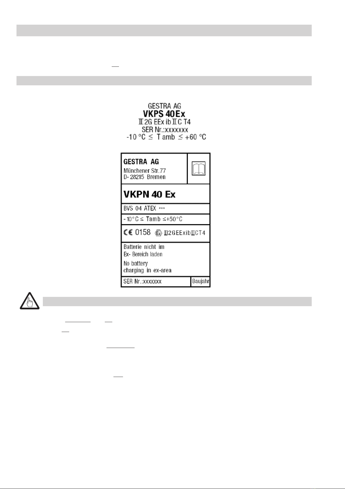
Safety Notes for VKP 40Ex
Notes.................................................................................................................................................................................................. 4, 5
Application ............................................................................................................................................................................................ 5
Maintenance notes VKPN 40Ex; VKPS 40Ex............................................................................................................................................. 5
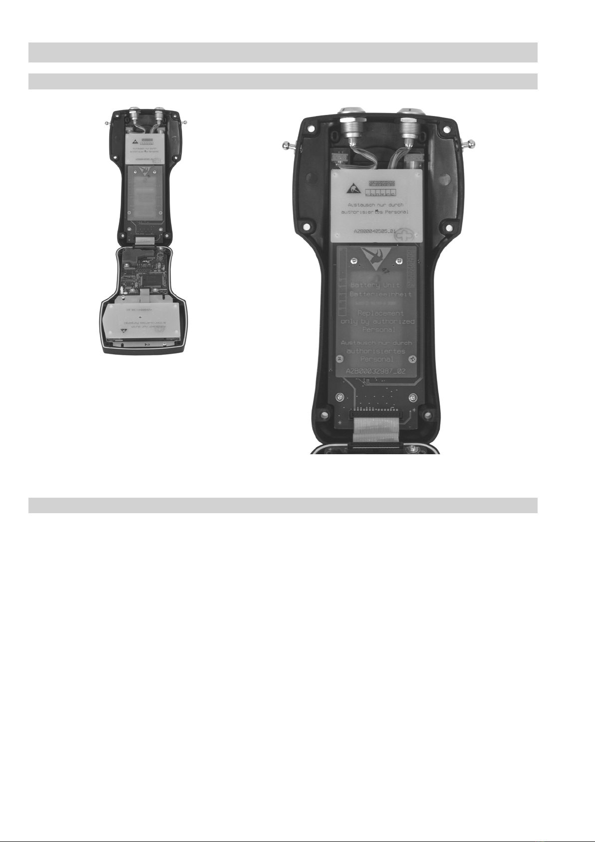
Replacing storage batteries VKPN 40Ex............................................................................................................................................... 5, 6
Environmental requirements ................................................................................................................................................................... 6
System description VKP 40Ex, VKP 40
System requirements.............................................................................................................................................................................. 7
Data collector VKPN 40Ex, VKPN 40 ........................................................................................................................................................ 7
Measuring transducer VKPS 40Ex ........................................................................................................................................................... 7
Connecting cable VKPA 40 ...................................................................................................................................................................... 7
Test duration........................................................................................................................................................................................... 7
Dimensions and weights......................................................................................................................................................................... 8
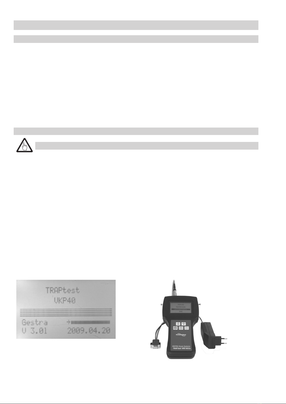
Charging storage batteries of VKPN 40Ex, VKP 40 .................................................................................................................................. 8
Replacing storage batteries of VKPN 40 (VKPN 40Ex see section “Safety Notes”) .................................................................................... 9
Maintaining VKP 40................................................................................................................................................................................. 9
Spare parts............................................................................................................................................................................................. 9
Connecting and Commissioning Data Collector VKPN 40Ex, VKPN 40
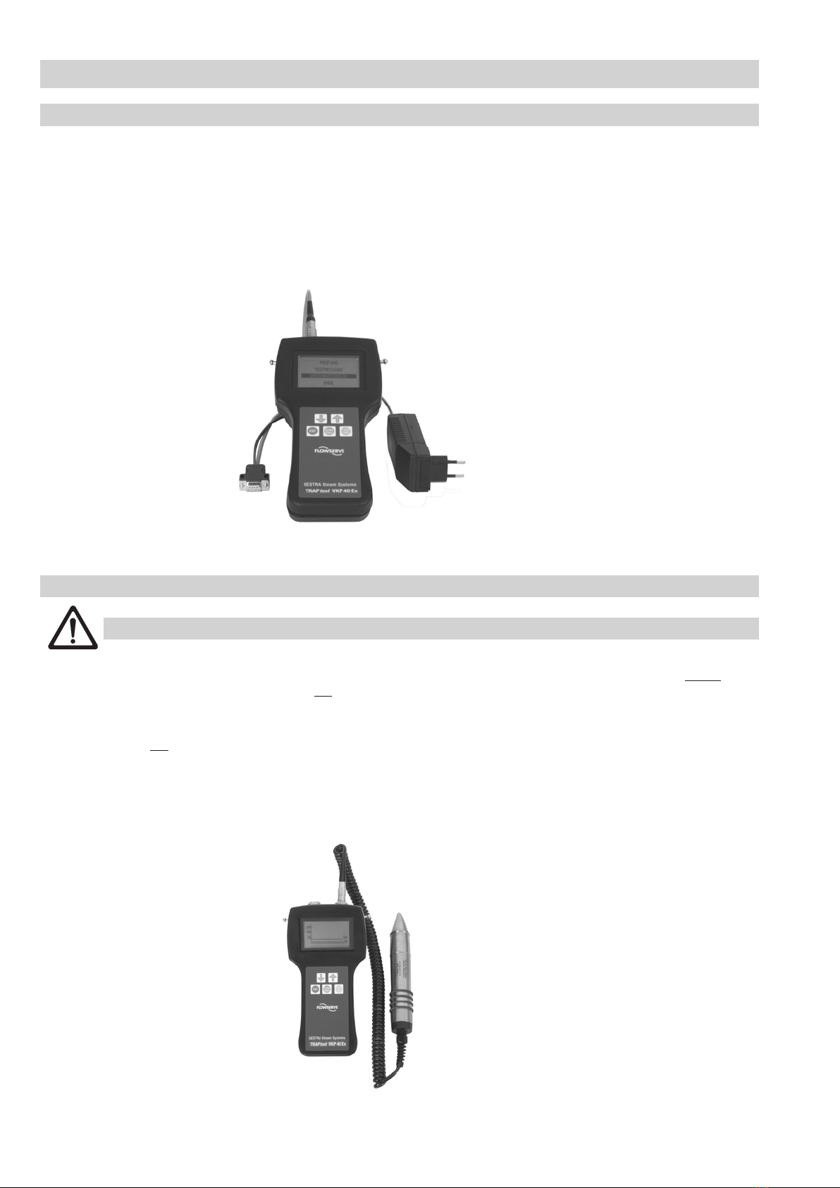
Connecting data collector VKPN 40Ex or VKPN 40 to a PC ..................................................................................................................... 10
Connecting measuring transducer VKPS 40Ex to data collector VKPN 40Ex or VKPN 40 ......................................................................... 10
Commissioning data collector VKPN 40Ex or VKPN 40........................................................................................................................... 11
Switching off data collector................................................................................................................................................................... 12
Automatic de-activation........................................................................................................................................................................ 12
TRAPtest Software PC Program
Installing PC software ........................................................................................................................................................................... 13
Starting and quitting program ............................................................................................................................................................... 13
Deinstalling PC software ....................................................................................................................................................................... 13
Software menus at a glance ........................................................................................................................................................... 13, 14
Data Exchange between PC and Data Collector VKPN 40Ex or VKPN 40
VKPN 40Ex or VKPN 40 ......................................................................................................................................................................... 15
Checking Steam Traps
Test .............................................................................................................................................................................................. 16 – 18
Test measurement ................................................................................................................................................................................ 19
Foreign noise........................................................................................................................................................................................ 20
Reference points for measurement ................................................................................................................................................. 20, 21
Troubleshooting
Data collector VKPN 40EX, VKPN 40 ...................................................................................................................................................... 22
Measuring transducer VKPS 40Ex ......................................................................................................................................................... 22
PC screen display ................................................................................................................................................................................. 22
EC Type Approval Certificate
EC Type Approval .................................................................................................................................................................................. 23