GESTRA NRG 16-41 User manual

1
EN
English
Original Installation Instructions
810743-04
Level Electrode
NRG 16-41
NRG 16-41.1
NRG 17-41
NRG 17-41.1
NRG 19-41
NRG 19-41.1

2
Contents
Page
Usage for the intended purpose ..............................................................................................................4
Safety note .............................................................................................................................................4
Danger ...................................................................................................................................................4
Attention.................................................................................................................................................4
ATEX (Atmosphère Explosible).................................................................................................................4
Note on the Declaration of Conformity / Declaration by the Manufacturer .........................................4
Important Notes
Explanatory Notes
Scope of supply......................................................................................................................................5
Description .............................................................................................................................................5
Function .................................................................................................................................................6
System components ...............................................................................................................................6
Design....................................................................................................................................................6
NRG 16-41, -41.1; NRG 17-41, -41.1; NRG 19-41, -41.1, step 1...........................................................14
NRG 16-41, -41.1; NRG 17-41, -41.1; NRG 19-41, -41.1, step 2...........................................................14
Attention...............................................................................................................................................14
Note .....................................................................................................................................................14
Tools.....................................................................................................................................................14
Examples of installation NRG 16-41.1, NRG 17-41.1, NRG 19-41.1.......................................................15
Key.......................................................................................................................................................16
Installation
NRG 16-41, -41.1; NRG 17-41, -41.1; NRG 19-41, -41.1 ........................................................................7
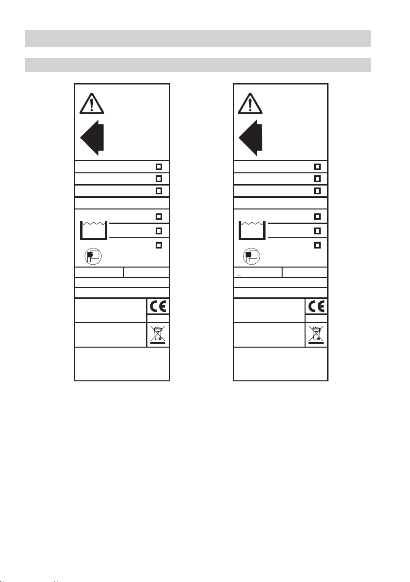
Name plate / marking .............................................................................................................................8
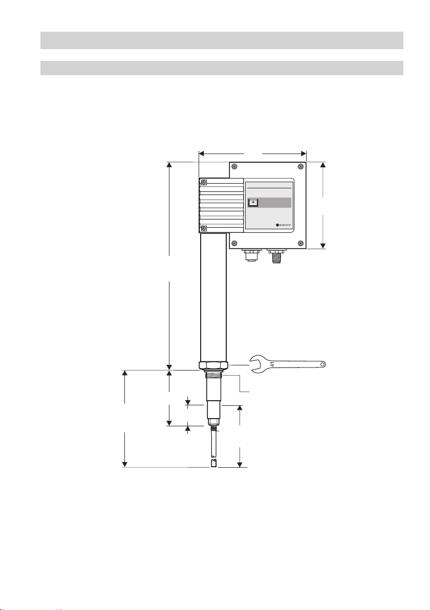
Dimensions NRG 16-41, -41.1; NRG 17-41, -41.1...................................................................................9
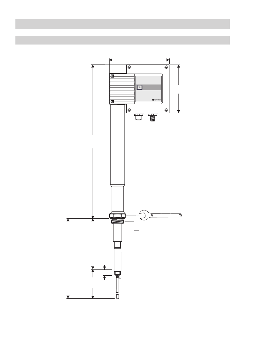
Dimensions NRG 19-41, -41.1..............................................................................................................10
Technical Data
NRG 16-41, -41.1; NRG 17-41, -41.1; NRG 19-41, -41.1 ......................................................................11
Key.......................................................................................................................................................13
Design
NRG 16-41, -41.1; NRG 17-41, -41.1; NRG 19-41, -41.1 ......................................................................12
Key.......................................................................................................................................................13
Functional Elements

3
Electrical Connection
Aligning terminal box............................................................................................................................17
Note .....................................................................................................................................................17
Control cable ........................................................................................................................................17
Wiring diagram.....................................................................................................................................18
Wiring diagram for the sensor plug-in connections ...............................................................................19
Key.......................................................................................................................................................19
CAN bus wiring diagram .......................................................................................................................20
Attention...............................................................................................................................................20
Note .....................................................................................................................................................21
Tools.....................................................................................................................................................21
Contents – continued –
Page
Malfunctions
Fault finding list for troubleshooting......................................................................................................26
Operation
High-water level limiter (Max alarm) .....................................................................................................25
Note .....................................................................................................................................................25
Commissioning Procedure
Check wiring ........................................................................................................................................25
Apply mains voltage..............................................................................................................................25
Basic Settings
CAN bus ...............................................................................................................................................21
Node ID ................................................................................................................................................22
Factory set default values .....................................................................................................................23
Assigning / changing node ID................................................................................................................23
Attention...............................................................................................................................................23
Code switch settings.............................................................................................................................24

4
Important Notes
Usage for the intended purpose
Use level electrode type NRG 16-41, NRG 17-41 or NRG 19-41 only in conjunction with control
equipment NRS 1-41 or NRS 1-40.1 as high-water level limiter (high-level alarm).
Use level electrode type NRG 16-41.1, NRG 17-41.1 or NRG 19-41.1 only in conjunction with control
equipment NRS 1-40.1 as high-water level limiter (high-level alarm).
Danger
When loosening the electrode steam or hot water might escape.
This presents the danger of severe scalding. It is therefore essential not to remove
the electrode unless the boiler pressure is verified to be zero.
The electrode is hot during operation. This presents the danger of severe burns to hands
and arms. Installation and maintenance work should only be carried out when the
system is cold.
If the internal ceramic insulation breaks, hot steam can escape through the lateral vent
hole on the electrode body. This presents the risk of severe scalding. Do not stay near
the electrode during operation.
Safety note
The equipment must only be installed and commissioned by qualified staff.
Maintenance and service work must only be performed by adequately trained persons who have
a recognized level of competence.
Attention
The name plate indicates the technical specification of the equipment.
Do not commission or operate equipment without a name plate.
ATEX (Atmosphère Explosible)
According to the European Directive 2014/34/EU the equipment must not be used in explosion-risk areas.
Note on the Declaration of Conformity / Declaration by the Manufacturer
For details on the conformity of our equipment according to the European Directives see our
Declaration of Conformity or our Declaration of Manufacturer.
The current Declaration of Conformity / Declaration of Manufacturer are available in the Internet
under www.gestra.com/documents or can be requested from us.

5
Explanatory Notes
Scope of supply
NRG 16-41, NRG 16-41.1
1 Level electrode type NRG 16-41 or NRG 16-41.1
1 S. S. joint ring D 27 x 32 mm to DIN 7603 (made of 1.4301), bright annealed
1 Terminating resistor 120 Ω
1 Installation manual
NRG 17-41, NRG 17-41.1
1 Level electrode type NRG 17-41 or NRG 17-41.1
1 S. S. joint ring D 27 x 32 mm to DIN 7603 (made of 1.4301), bright annealed
1 Terminating resistor 120 Ω
1 Installation manual
NRG 19-41, NRG 19-41.1
1 Level electrode type NRG 19-41 or NRG 19-41.1
1 S. S. joint ring D 27 x 32 mm to DIN 7603 (made of 1.4301), bright annealed
1 Terminating resistor 120 Ω
1 Installation manual
Description
The level electrode operation is based on the conductive measuring principle.
The NRG 1...-41 and NRG 1...-41.1 are designed for signalling the max. liquid level in electrically
conductive liquids.
nOne liquid level with one switchpoint
The NRG 1...-41 is to be used in conjunction with the switching controller NRS 1-41 or NRS 1-40.2,
the NRG 16-41.1 is designed for use with switching controller NRS 1-40.1.
The level data are transferred from the electrode NRG 1...-41 and NRG 1...-41.1 to the control equip-
ment via a CAN bus using the CANopen protocol.

6
Explanatory Notes – continued –
System components
NRS 1-41
Digital switching controller for high-level limiter NRG 1...-41
Functions: High-level alarm (Max)
Data exchange: CAN bus to DIN ISO 11898 using CANopen protocol.
NRS 1-40.1
Digital multi-purpose switching controller for high-level limiter NRG 1...-41.1, the low-level electrode
NRG 1...-40 and the temperature limiter TRV 5-40
Functions: Signalling high-level alarm (Max), low-level alarm (Min)
Data exchange: CAN bus to DIN ISO 11898 using CANopen protocol.
NRS 1-40.2
Digital multi-purpose switching controller for high-level limiter NRG 1...-41 and the
temperature limiter TRV 5-40
Functions: Signalling high-level alarm (Max)
Data exchange: CAN bus to DIN ISO 11898 using CANopen protocol.
URB 1, URB 2
Control terminal and display unit
Functions: Parameterization and visual display (LCD)
Data exchange: CAN bus to DIN ISO 11898 using CANopen protocol.
Design
NRG 16-41, NRG 16-41.1, NRG 17-41, NRG 17-41.1, NRG 19-41, NRG 19-41.1:
Screwed ¾", EN ISO 228-1. Fig. 2, Fig. 3
Function
The conductivity of the liquid is used to signal the liquid level. Some liquids are conductive, which
means that they allow an electric current to flow through them. For the safe functioning of this device a
minimum conductivity of the liquid to be measured is required.
The conductivity measurement method can detect two conditions: electrode rod submerged or
exposed, meaning switchpoint reached (or exceeded) or not yet reached. Before installation, the length
of the electrode rod must be cut to the required switching level, e. g. for “Pump off” or “Control valve
closed” or, in case of economiser and air heaters that are installed close to the steam-generating unit
and exposed to a risk, “Firing/Burner off”.
An additional electrode fully integrated in the system automatically monitors the electrical resistance
path between earth and measuring electrode. As soon as the actual value falls below the admissible
resistance value the protection circuit is interrupted and cuts off the pump or heat supply to the boiler.
At regular intervals the level electrode NRG 1...-41 / NRG 1...41.1 sends a data telegram to the
switching controller NRS 1-41, NRS 1...40.1. The data are transferred via a CAN bus to DIN ISO 11898
using the CANopen protocol.

7
NRG 16-41, -41.1; NRG 17-41, -41.1; NRG 19-41, 19-41.1
Type Approval
TÜV · SWB / SHWS · ..-403
TÜV · SWB / SHWS · ..-413
Service pressure
NRG 16-41, NRG 16-41.1 NRG 17-41, NRG 17-41.1 NRG 19-41, NRG 19-41.1
32 bar g at 238 °C 46 bar g at 260 °C 100 bar g at 311 °C
Connection
Screwed ¾", EN ISO 228-1
Materials
Terminal box: Die cast aluminium 3.2161 (G AlSi8Cu3)
Sheath: 1.4301 X5 CrNi18-10
Screwed union: S. S. 1.4571 (X6CrNiMoTi17-12-2)
Measuring electrode: S. S. 1.4401 (X5CrNiMo17-12-2)
Electrode insulation: PEEK
Lengths supplied
500 mm, 1000 mm, 1500 mm
Sensitivity of response
> 0.5 µS/cm at 25 °C
Supply voltage
18 – 36 V DC (coming from NRS 1-41, NRS 1-40.1, NRS 1-40.2)
Current consumption
35 mA
Fuse
Electronic thermal fuse Tmax = 85 °C
Hysteresis
-2 K
Electrode voltage
2 Vss
Data exchange
CAN bus to DIN ISO 11898, CANopen Protocol
Indicators and adjustors
One 10-pole code switch for setting node ID and baud rate
Two LEDs “PrograM running”
Two LEDs “can bus coMMunication”
Electric connection
M 12 sensor plug, 5 poles, A-coded,
M 12 sensor socket, 5 poles, A-coded
Protection
IP 65 to DIN EN 60529
Max. admissible ambient temperature
70 °C
Weight
Approx. 2.5 kg
Technical Data

8
Technical Data – continued –
Name plate / Marking
Fig. 1
Betriebsanleitung
beachten
See installation instructions
Hier öffnen
Open here
Ouvrir ici
Voir instructions de
montage
18-36 V DC
Tamb = 70°C (158°F)
IN/OUT: CAN-Bus
PN 63
PN 160
PN 40
Pmax
Tmax
NRG 17 - 41.1
NRG 19 - 41.1
NRG 16 - 41.1
G 3/4 1.4571 IP65
46 bar (667psi)
260°C (500°F)
32 bar (464psi)
238°C (460°F)
100 bar (1450psi)
311°C (592°F)
Node ID: __ __ __
0525
GESTRA AG
Münchener Str. 77
D-28215 Bremen
TÜV . SWB/SHWS
STW(STB) . xx - 413
0,5 µS/cm>
Betriebsanleitung
beachten
See installation instructions
Hier öffnen
Open here
Ouvrir ici
Voir instructions de
montage
18-36 V DC
Tamb = 70°C (158°F)
IN/OUT: CAN-Bus
PN 63
PN 160
PN 40
Pmax
Tmax
NRG 17 - 41
NRG 19 - 41
NRG 16 - 41
G 3/4 1.4571 IP65
60 bar (870psi)
260°C (500°F)
32 bar (464psi)
238°C (460°F)
100 bar (1450psi)
311°C (592°F)
Node ID: __ __ __
0525
GESTRA AG
Münchener Str. 77
D-28215 Bremen
TÜV. SWB / SHWS . xx - 403
TÜV . SWB/SHWS
STW(STB) . xx - 413

9
GESTRA Steam Systems
GESTRA
NRG 1...-41.1
MAX
Fig. 2
¾" EN ISO 228-1
1500,
1000,
1500
140
337.5
≥ 185
Technical Data – continued –
Dimensions NRG 16-41, -41.1; NRG 17-41, -41.1
175
85
30

10
GESTRA Steam Systems
GESTRA
NRG1...-41.1
MAX
Fig. 3
¾" EN ISO 228-1
1500,
1000,
1500
175
140
419
30
≥185
120
Technical Data – continued –
Dimensions NRG 19-41, -41.1

11
Fig. 6
Fig. 4
Fig. 5
Fig. 7
N8
N 10
0.5
¾" EN ISO 228-1
∅33
Design
NRG 16-41, -41.1; NRG 17-41, -41.1; NRG 19-41, 19-41.1
5
f
6
7
1
2
3
4

12
K
H
11
22
3
3
12345
LW HW
123 5674 8910
ON
PRODUCT
DESIGN AWARD
MAX
Functional Elements
Fig. 8
Fig. 9
NRG 16-41, -41.1; NRG 17-41, -41.1; NRG 19-41, 19-41.1
9098
a
e
d
b
c

13
1Electrode rod
2Bore
3Spring
4Electrode tip
5S. S. joint ring D 27 x 32 mm to DIN 7603 (made of 1.4301), bright annealed
6Seating surface
7Electrode thread
8Screws M 4
9M 12 sensor plug, 5 poles, A-coded, M 12 sensor socket, 5 poles, A-coded
0Cover
aLED green “Program running”, LED red “CAN bus communication”
b10-pole code selector for setting node ID and baud rate
cTerminal strip
dPE connection
ePlug
fThermal insulation (provided on site), d = 20 mm (outside of thermal insulation of steam
generating unit)
Design / Functional Elements – continued –
Key

14
Attention
nThe seating surfaces of the standpipe or the flange provided on the vessel must be
accurately machined, see Fig. 7.
nDo not bend electrode tip when mounting.
nUse only ring joint (of stainless steel 1.4301) D 27 x 32 to DIN 7603 supplied with
the electrode.
nDo not lag electrode body above the hexagonal section, Fig. 5.
nDo not insulate electrode thread with hemp or PTFE tape.
nDo not screw electrode directly into a screwed socket, Fig. 6.
nObserve min. spacing when installing the electrode, Fig. 6, Fig. 10, Fig. 11, Fig. 12
Installation
NRG 16-41, -41.1; NRG 17-41, -41.1; NRG 19-41, 19-41.1, step 1
1. Screw electrode tip 4into measuring electrode 1, Fig. 4.
2. Carefully determine required measuring length of electrode. Observe min. length, Fig. 2, Fig. 3.
3. Mark length of electrode tip 4.
4. Unscrew electrode tip 4from measuring electrode 1and cut tip.
5. After visual inspection screw electrode tip 4into measuring electrode 1. Slide spring 3along
electrode tip 4, so that its end completely enters into small bore 2.
Note
nFor the approval of the boiler standpipe the relevant regulations must be considered.
nRefer to page 15 for three typical installation examples.
Tools
nOpen-end spanner A. F. 17 mm
nOpen-end spanner A. F. 41 mm
nHacksaw
nFlat file, medium cut
NRG 16-41, -41.1; NRG 17-41, -41.1; NRG 19-41, 19-41.1, step 2
1. Check seating surfaces, Fig. 6
2. Place ring joint 5supplied with electrode onto seating surface 6of electrode, Fig. 5
3. Apply a light smear of silicone grease (e.g. Molykote®111) to electrode thread 7.
4. Screw level electrode into threads of flange provided on vessel and tighten with
a 41 mm open end spanner. The torque required is 160 Nm when cold.
5. When installing two electrodes together in one flange install the first electrode as described in 4.
Before mounting the second electrode undo plug e, remove PE connection dand strip cable lugs
from the board. Screw in electrode. Slightly tighten plug e. Install PE connection dand insert
cable lugs.
Molykote®111 is a registered trademark of DOW Corning Corp., Midland Michigan, USA

15
4
DN 100
Fig. 11
DN 20
DN 20
24.5 24.5
20
∅20
Fig. 10
Fig. 12
¾"
1"
≥ 20
≤ 3000
DN 20
∅20
¾"
≤ 90°
≥10
Installation – continued –
Examples of installation NRG 16-41.1, NRG 17-41.1, NRG 19-41.1
i
g
h
k
m
n
9
0
Centre distance
g
j
o
k
1
∅ 20
20
DN 50
∅20
≤ 90°
g
h
i
n
k
l
j
o
p
¾"
j
j

16
g Flange PN 40, DN 50, DIN 2527
Flange PN 40, DN 100, DIN 2527
h For the approval of the boiler standpipe with connecting flange the relevant regulations
must be considered.
i Vent hole (Provide vent hole as close to the boiler wall as possible)
j High water level (HW)
k Electrode rod d = 8 mm
l Protection tube DN 80
m Protection tube DN 100
n Electrode distance ≥14 mm
o Low water level
p Reducer DIN 2616-2, K-88.9 x 3.2- 42.4 x 2.6 W!
q Reducer DIN 2616-2, K-114.3 x 3.6- 48.3 x 2.9 W
Installation – continued –
Key

17
Electrical Connection
1. Unscrew screws 8and remove cover 0. Fig. 13
2. Loosen nut ewith 19 mm spanner. Do not remove it! Fig. 14
The electrode terminal box can now be turned through +/– 180°.
3. Turn electrode terminal box into desired position (+/– 180°).
4. Tighten nut ewith a torque of 25 Nm.
5. Set node ID (see “Basic Settings”, “Configuring level electrode”).
6. Re-attach cover 0and fix it with screws 8.
Control cable
UNITRONIC®is a registered trademark of LAPP Kabelwerke GmbH, Stuttgart.
Aligning terminal box
Note
nWire the control cable according to the wiring diagram with connector socket and plug.
NRS, NRR, LRR, TRS, URB 1
To wire the equipment screened multi-core twisted-pair control cable must be used for the bus line,
e. g. UNITRONIC®BUS CAN 2 x 2 x ... mm2or RE-2YCYV-fl 2 x 2 x ... mm2.
Control cable assemblies (2 x 2 x 0.32 mm² cable with plug and socket) of various lengths are available
as add-on equipment.
NRG, LRG, EF, URZ, TRV, URB 2
The equipment is fitted with sensor plug-in connectors (5 poles, A-coded). For connecting the bus
devices control cable assemblies (with plug and socket) of various lengths are available as add-on
equipment.
Note that the recommended control cables are not UV-resistant and must be protected by a
UV-resistant plastic tube or cable duct if the equipment is installed outdoors (except for URB 2).
The baud rate (data transfer rate) dictates the cable length and size between the bus nodes. The total
power consumption must also be taken into consideration when selecting the conductor size. The
total power consumption is obtained from the number of bus nodes. If the cable length between the
steam boiler and the control cabinet exceeds 15 m, we recommend that you fit a branching box that is
resistant to electromagnetic interference (stock code 1501214) and use a control cable with a larger
conductor size for the distance to the control cabinet.
S 8 S 9 S 10 Baud rate Cable length Number of pairs
and conductor size [mm2]
OFF ON OFF 250 kBit/s 125 m 2 x 2 x 0.34
Factory setting
ON ON OFF 125 kBit/s 250 m 2 x 2 x 0.5
OFF OFF ON 100 kBit/s 335 m 2 x 2 x 0.75
ON OFF ON 50 kBit/s 500 m on request, depending on
bus configuration
OFF ON ON 20 kBit/s 1000 m
ON ON ON 10 kBit/s 1000 m
Set baud rate via code switch b. Make sure that all bus nodes feature the same settings.

18
NRG 1...-41.1
HW
1
2
3
S
CL
CH
18V-36V DC
CAN-Bus
+
120 Ω
12345
1
ON 234567890
Electrical Connection – continued –
Wiring diagram
r
s
Fig. 13
r
s

19
Wiring diagram for the sensor plug-in connections
Fig. 14 vtw wtuuvr r
Electrical Connection – continued –
Fig. 15 RES 1 Fig. 16 RES 2
r Terminating resistor 120 Ω, RES 1 or RES 2
s CAN bus line, twisted pair control cable
t Pin 1: Screen
u Pin 2: Power supply 24 V DC+ (red)
v Pin 3: Power supply 24 V DC– (black)
w Pin 4: CAN data line CH(white)
x Pin 5: CAN data line CL(blue)
Key
x x
120 Ω 120 Ω

20
Electrical Connection – continued –
CAN bus wiring diagram
Fig. 17
RES 2
CEP NRS, NRR, LRR,
TRS, URB 1
URB 2 NRG, LRG,
EF, URZ TRV
RES 1
Attention
nWire equipment in series. Star-type wiring is not permitted!
nThe Bus line must run separately from signal and mains lines.
nLink screens of control cables such that electrical continuity is ensured and connect
them once to the central earthing point (CEP). If equipotential bonding currents are
to be expected, for instance in outdoor installations, make sure that the screen is
separated from the central earthing point (CEP).
nTo protect the switching contacts fuse circuit with T 2.5 A or according to TRD
regulations (1.0 A for 72 h operation).
nIf two or more system components are connected in a CAN bus system, provide the
first and the last device with a terminating resistor of 120 Ω, Fig. 15, Fig. 16
n Note that in a CAN bus network only one water-level limiting system may be used.
nDo not interrupt the CAN bus network during operation with one or more system
components!
If the CAN bus network is interrupted the saftey circuit will be opened.
Before taking the CAN bus line from the terminal strip, make sure that all connected
system components are out of service.
This manual suits for next models
5
Table of contents
Other GESTRA Industrial Equipment manuals

GESTRA
GESTRA BK 45 User manual

GESTRA
GESTRA QuickCC User manual

GESTRA
GESTRA TA 50 User manual

GESTRA
GESTRA VKP 40Ex Manual

GESTRA
GESTRA UNA 45 User manual

GESTRA
GESTRA FPS 11 User manual

GESTRA
GESTRA RHOMBUSline MK 45-1 User manual

GESTRA
GESTRA UNA 38 User manual

GESTRA
GESTRA NRG 26-60 Installation instructions