GESTRA BA 46 User manual

1
GESTRA Steam Systems
BA 46
BA 46-ASME
BA 47
BA 47-ASME
BAE 46...
BAE 46...-ASME
BAE 47...
BAE 47...-ASME
Installation Instructions / Product Information
818609-03
Continuous Blowdown Valve
BA 46 / BA 46-ASME, PN 40/CL 150/300, DN 15-DN 50
BA 47 / BA 47-ASME, PN 63/CL 600, DN 25, 40, 50
BAE 46... / BAE 46...-ASME, PN 40/CL 150/300, DN 15-DN 50
BAE 47... / BAE 47...-ASME, PN 63/CL 600, DN 25, 40, 50
EN
English

2
Contents
Page
Important notes
Usage for the intended purpose...............................................................................................................5
Safety note..............................................................................................................................................5
PED (Pressure Equipment Directive) ........................................................................................................6
ATEX (Hazardous Area) ............................................................................................................................6
Note on the Declaration of Conformity / Manufacturer's Declaration ..............................................6
Explanatory Notes
Scope of supply ......................................................................................................................................7
Description..............................................................................................................................................8
Function ................................................................................................................................................9
Technical Data
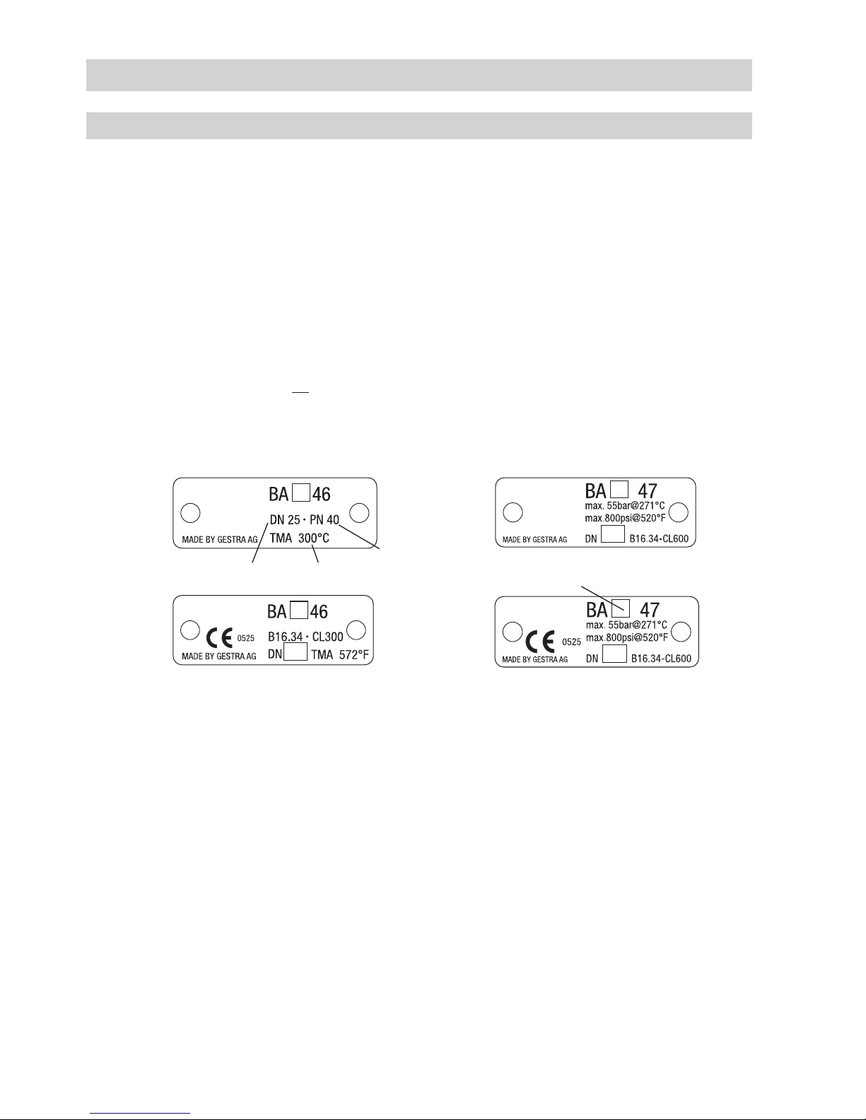
Name plate / marking ...........................................................................................................................10
Dimensions BA 46, BA 47......................................................................................................................11
Dimensions BAE 46..., BAE 47...............................................................................................................12
Dimensions of flanged ends (extract).....................................................................................................13
Dimensions of butt-weld ends (extract) .................................................................................................14
Dimensions of socket-weld ends (extract) .............................................................................................14
Pressure /Temperature Ratings & End Connections ...............................................................................15
Materials...............................................................................................................................................16
Actuator ................................................................................................................................................16
Capacity chart for DN 15 to 32, capacity ranges at a glance..................................................................17
Capacity chart for DN 15 to 32 , capacity range up to 310 kg/h............................................................18
Capacity chart for DN 15 to 32 , capacity range up to 1020 kg/h..........................................................19
Capacity chart for DN 15 to 32 , capacity range up to 2120 kg/h..........................................................20
Capacity chart for DN 40 and 50, capacity ranges at a glance ...............................................................21
Capacity chart for DN 40 and 50, capacity range up to 1340 kg/h ........................................................22
Capacity chart for DN 40 and 50, capacity range up to 4500 kg/h ........................................................23
Capacity chart for DN 40 and 50, capacity range up to 6300 kg/h ........................................................24
Design
BA 46, BA 47.........................................................................................................................................25
BAE 46..., BAE 47..................................................................................................................................26
Key .......................................................................................................................................................27

3
Contents
Page
Installation
BA 46, BA 47, BAE 46..., BAE 47............................................................................................................28
Flanged design......................................................................................................................................28
Butt-weld design...................................................................................................................................28
Socket-weld design ..............................................................................................................................28
Heat treatment of welds........................................................................................................................29
Reposition control lever by 180
° (if position of installation of BA 46 or BA 47 is unfavourable) ..............29
Install sampling valve (if desired)...........................................................................................................29
Electrical connection
Continuous blowdown valves BAE 46..., BAE 47... with actuator............................................................30
Factory settings for BAE 46..., BAE 47... ................................................................................................30
Commissioning procedure
BA 46, BA 47, BAE 46..., BAE 47............................................................................................................31
Calculating the amount of boiler blowdown...........................................................................................31
Continuous blowdown valves BA 46, BA 47 without actuator.................................................................31
Continuous blowdown valves BAE 46..., BAE 47... with actuator............................................................31
Operation
BA 46, BA 47, BAE 46..., BAE 47............................................................................................................32
Purging .................................................................................................................................................32
Emergency operation
BAE 46..., BAE 47..................................................................................................................................32
Maintenance
BA 46, BA 47, BAE 46..., BAE 47............................................................................................................33
Changing packing and internals of BA 46, BA 47 ..................................................................................33
BAE 46..., BAE 47... Changing packing and internals .............................................................................34
Tightening torques ................................................................................................................................35
Tools .....................................................................................................................................................35
Removing internals ...............................................................................................................................36
- continued -

4
Contents - continued -
Page
Retrofitting
Mounting the actuator...........................................................................................................................37
Tightening torques ................................................................................................................................37
Tools .....................................................................................................................................................37
Spare Parts
Spare parts list......................................................................................................................................38
Parts for retrofitting
List of parts for retrofitting.....................................................................................................................39
Decommissioning
Disposal................................................................................................................................................39

5
Important notes
Usage for the intended purpose
BA 46, BA 47:
Use the continuous blowdown valves BA 46, BA 47 only for discharging boiler blowdown from steam
boilers. Use the equipment only within the allowable pressure and temperature ratings and only if the
chemical and corrosive influences on the equipment are taken into account.
BAE 46, BAE 46-1, BAE 46-3, BAE 46-3-1, BAE 47, BAE 47-1:
Use continuous blowdown valve BAE 46..., BAE 47... only in conjunction with control units KS 90,
LRR 1-40 or LRR 1-5 for the discharge of boiler blowdown from steam boilers. Use the equipment
only within the allowable pressure and temperature ratings and only if the chemical and corrosive
influences on the equipment are taken into account.
To ensure safe operation of the BAE 46..., BAE 47... only actuators named and specified by GESTRA
may be installed on the valve. Specified and approved actuators are: ARIS EF 0.7, ARIS EF 0.7-1,
ARIS EF 10 and ARIS EF 10-1.
Danger
The valve is under pressure during operation.
When loosening flanged connections, sealing plugs or stuffing boxes, hot water and
steam will escape.
The valve becomes hot during operation.
Risk of severe burns and scalds to the whole body!
Before carrying out any maintenance work on the valve or loosening flanged con-
nections, stuffing box unions or sealing plugs make sure that all connected lines are
depressurized (zero bar) and cooled down to room temperature (20 °C).
Sharp edges on internals present the danger of cuts to hands.
Always wear industrial gloves when replacing the packing, valve seat or valve plug!
Danger of bruising! During operation moving internal parts can pinch one's hands or
fingers, causing severe injuries. Do not touch moving parts. The continuous blowdown
valves BAE 46..., BAE 47... are remote-controlled and can open and close abruptly.
The terminal strips of the actuator EF... are live during operation. This presents the
danger of electric shock!
Cut off power supply to the equipment before mounting or removing the equipment!
Safety note
The equipment must only be installed and commissioned by qualified and competent staff.
Retrofitting and maintenance work must only be performed by qualified staff who - through adequate
training - have achieved a recognised level of competence.

6
PED (Pressure Equipment Directive)
The equipment fulfils the requirements of the Pressure Equipment Directive PED 97/23/EC.
For use with fluids of group 2. With CE marking (apart from equipment that is excluded from the scope of
the PED as specified in section 3.3).
Important Notes - continued -
Attention
The name plate specifies the technical features of the equipment. Do not commission or
operate any item of equipment that does not bear its specific name plate.
ATEX (Hazardous Area)
The equipment BA 46, BA 47 can be used in potentially explosive areas, provided that the following
notes are observed:
The service fluid must not generate excessively high operating temperatures. Electrostatic charges
that may be produced during operation must be discharged. The tight shut-off of the stuffing box must
be ensured. The valve spindle must be able to move smoothly.
Can be used in Ex zones 1, 2, 21, 22 (1999/92/EC), II 2 G/D c X.
According to the European Directive 94/9/EC the equipment BAE 46..., BAE 47... must not be used in
potentially explosive areas.
For more information refer to our ATEX Declaration of Conformity.
Note on the Declaration of Conformity / Manufacturer's Declaration
For details on the conformity assessment according to the European Directives see our Declaration of
Conformity or our Declaration of Manufacturer.
The current Declaration of Conformity or Declaration of Manufacturer is available in the Internet under
www.gestra.com documents
or can be requested from us.
Manufacturer GESTRA AG
Münchener Straße 77
28215 Bremen
Germany
Telefon +49 421 3503-0
Telefax +49 421 3503-393
Web www.gestra.de
This declaration is no longer valid if modifications are made to the equipment without consultation
with us.

7
Explanatory Notes
Scope of supply
BA 46
1 Continuous blowdown valve REAKTOMAT BA 46
1 Sample valve (supplied but not fitted)
1 Gasket A17 x 23 x 1.5
1 Installation manual GESTRA
1 Installation manual for sample valve
BA 47
1 Continuous blowdown valve REAKTOMAT BA 47
1 Sample valve (supplied but not fitted)
1 Gasket A17 x 23 x 1.5
1 Installation manual GESTRA
1 Installation manual for sample valve
Retrofitting kit for BA 46, BA 47
1 Electric actuator
EF 0.7, EF 0.7-1, EF 10 or EF 10-1
1 Mounting kit for coupling / mounting bracket
1 Installation manual for ARIS actuator EF...
Spare parts
1 Kit according to spare parts list, page 38.
BAE 46...
1 Continuous blowdown valve REAKTOMAT BAE
46...
1 Sample valve (supplied but not fitted)
1 Gasket A17 x 23 x 1.5
1 Installation manual GESTRA
1 Installation manual for sample valve
1 Installation manual ARIS for actuator EF...
1 Manufacturer's Declaration
BAE 47...
1 Continuous blowdown valve REAKTOMAT BAE
47...
1 Sample valve (supplied but not fitted)
1 Gasket A17 x 23 x 1.5
1 Installation manual GESTRA
1 Installation manual for sample valve
1 Installation manual ARIS for actuator EF...
1 Manufacturer's Declaration

8
Description
Due to the continuous evaporation process in the steam boiler the density and hence the TDS (= Total
Dissolved Solids) concentration of the boiler water is increased. If the TDS (= total dissolved solids)
concentration exceeds the limit defined by pertinent regulations and dictated by the boiler manufacturer,
foaming and priming occurs as the density of the boiler water increases, resulting in a carry-over of
solids with vapour into steam lines and superheaters.
As a consequence, the operational safety is impaired and severe damage to boiler and tubes may
occur. To keep the TDS concentration within admissible limits, a certain portion of boiler water must
be removed continuously and/or periodically and fresh make-up water must be added to the boiler to
compensate for the water lost through blowdown.
The continuous blowdown valves BA... and BAE... feature a specially designed and wear resistant nozzle
stem that enters concentrically into a system of expansion chambers which are arranged one after the
other, making these valves particularly suitable for the continuous discharge of boiler water at very high
differential pressure. The continuous blowdown valves BA... and BAE... are suitable for operation in
steam boiler plants according to TRD 604, EN 12952 and EN 12953.
■BA 46 PN 40, manually operated
■BA 47 PN 63, manually operated
■BAE 46 PN 40, operated by the electric actuator EF 101)
■BAE 46-1 PN 40, operated by the electric actuator EF 10-11)
■BAE 46-3 PN 40, operated by the electric actuator EF 0.71)
■BAE 46-3-1 PN 40, operated by the electric actuator EF 0.7-11)
■BAE 47 PN 63, operated by the electric actuator EF 101)
■BAE 47-1 PN 63, operated by the electric actuator EF 10-11)
■EF 0.7 ARIS actuator with two position-controlled limit switches and an operating cam for
intermediate positions
■EF 0.7-1 ARIS actuator with two position-controlled limit switches and feedback potentiometer
and an operating cam for intermediate positions
■EF 10 ARIS actuator with two position-controlled limit switches and an operating cam for
intermediate positions
■EF 10-1 ARIS actuator with two position-controlled limit switches and feedback potentiometer
and an operating cam for intermediate positions
1)
Explosion-proof actuators or actuators powered by d. c. or three-phase current are available on request.
Explanatory Notes - continued -

9
Continuous blowdown valve REAKTOMAT BA 46, BA 47
To open or close the continuous blowdown valve BA 46, BA 47 use the control lever and to set the required
amount of boiler blowdown use the scale. The required amount of boiler blowdown can be calculated with
the aid of a formula or read off on a nomogram.
Continuous blowdown valve REAKTOMAT BA 46..., BA 47...
Due to the continuous evaporation process the electrical conductivity of the boiler water is increased.
Electrical conductivity - as a result of the TDS (Total Dissolved Solids) content - is measured by a conduc-
tivity electrode LRG 1.-..or a conductivity transmitter LRGT 1.-.. in conjunction with the industrial controller
KS 90-1 or the conductivity controller LRR 1-.. . Depending on the adjusted setpoint the industrial controller
KS 90-1 or the conductivity controller LRR 1-.. operates the electric actuator EF... and opens and closes the
continuous blowdown valve.
The power flow towards the closing direction is transmitted via a coupling with integrated torsion spring.
The coupling permits the actuator to travel a little bit further when the nozzle stem is pressed into the valve
seat.
If a certain amount of boiler water is to be removed continuously via the continuous blowdown valve, make
sure that the valve is permanently slightly open to ensure a steady flow of water (valve is in operating posi-
tion). This operating position is adjustable and can be determined by using the capacity charts for the valve.
The valve positions OPEN and CLOSED are limited by the cam-operated switch located in the actuator, the
OPERATING POSITION is variably adjustable by means of an operating cam or a feedback potentiometer
(EF 10-1, EF 0.7-1). However, if the actuator EF 10-1 or EF 0.7-1 is controlled by the conductivity controller
LRR 1-52 or LRR 1-53 you can use the feedback potentiometer for indicating the valve position.
Function
Explanatory Notes - continued -

10
Fig. 1
Nominal pressure
Nominal size Code letter E
Max. admissible temperature
Name plate / marking
The temperature/pressure ratings are indicated on the body or on the name plate. For more informa-
tion see GESTRA technical documents such as data sheets and the Technical Information.
According to EN 19 the name plate or the specification on the body indicate the type and design:
■Name/logo of the manufacturer
■Type designation:
■Pressure class PN or Class
■Material number
■Max. temperature
■Max. pressure
■Direction of flow
■Stamp on valve body, e. g. specifies the quarter and the year of production
(example: 4th quarter 2016)
4
16
Technical Data

11
DN 15-32: 126
Fig. 2
Dimensions BA 46, BA 47
L
20 180
DN 15-32: 172
DN 40, 50: 213DN 40, 50: 132
Technical Data - continued -

12
DN 15-32: 126
Fig. 3
Dimensions BAE 46..., BAE 47...
L
20 100
DN 15-32: 385
DN 40, 50: 425DN 40, 50: 132
Technical Data - continued -

13
Dimensions of flanged ends (extract)
L
DN EN 1092-1 (2001)
PN 40
EN 1092-1 (2001)
PN 63
[inch] ½ ¾ 1 1¼ 1½ 2 1 1½ 2
[mm] 15 20 25 32 40 50 25 40 50
D 95 105 115 140 150 165 140 170 180
b 16 18 18 18 18 20 24 26 26
k 65 75 85 100 110 125 100 125 135
g 45 58 68 78 88 102 68 88 102
l 14 14 14 18 18 18 18 22 22
n444444444
L 150 150 160 180 200 230 190 220 250
[kg]*)
4.7/8.8 5.3/9.4 5.8/9.9 7.1/11.2 10.7/14.8 12.5/16.6 7.1/11.2 10.7/14.8 12.5/16.6
*) Weight BA 4... / Weight BAE 4...
L
DN ASME B16.5
Class 150
[inch] ½ ¾ 1 1¼ 1½ 2
[mm] 15 20 25 32 40 50
D 88.9 98.4 107.9 117.5 127.0 152.4
b 11.1 12.7 14.3 15.9 17.5 19.0
k 60.3 69.8 79.4 88.9 98.4 120.6
g 34.9 42.9 50.8 63.5 73.0 92.1
l 15.9 15.9 15.9 15.9 15.9 19.0
n444444
L 150 150 160 180 230 230
[kg]*)
4.7/8.8 5.3/9.4 5.8/9.9 7.1/11.2 10.7/14.8 12.5/16.6
*) Weight BA 4... / Weight BAE 4...
L
DN ASME B16.5
Class 300
ASME B16.5
Class 600
[inch] ½ ¾ 1 1¼ 1½ 2 1 1½ 2
[mm] 15 20 25 32 40 50 25 40 50
D 95.2 117.5 123.8 133.3 155.6 165.1 123.8 155.6 165.1
b 14.3 15.9 17.5 19.0 20.6 22.2 17.5 22.2 25.4
k 66.7 82.5 88.9 98.4 114.3 127 88.9 114.3 127
g 34.9 42.9 50.8 63.5 73.0 92.1 50.8 73.0 92.1
l 15.9 19.0 19.0 19.0 22.2 19.0 19.0 22.2 19.0
n444444444
L 150 150 160 180 230 230 216 216 250
[kg]*)
4.7/8.8 5.3/9.4 5.8/9.9 7.1/11.2 10.7/14.8 12.5/16.6 7.1/11.2 10.7/14.8 12.5/16.6
*) Weight BA 4... / Weight BAE 4...
Other designs available on request. Special dimensions, sizes and materials for end connections on request.
∅l
∅l
∅l
Technical Data - continued -

14
Dimensions of butt-weld ends (extract)
Dimensions of socket-weld ends (extract)
L
DN ASME B16.25, Schedule 40
ASME B36.10
ASME B16.25, Schedule 80
ASME B36.10
[inch] ½ ¾ 1 1¼ 1½ 2 1 1½ 2
[mm] 15 20 25 32 40 50 25 40 50
d222 28 34 43 49 61 34 49 61
d115.7 20.9 26.6 35.1 40.9 52.5 24.3 38.1 49.3
for pipe 21.3x2.8 26.7x2.9 33.4x3.4 42.2x3.6 48.3x3.7 60.3x3.9 33.4x4.5 48.3x5.1 60.3x5.5
L 200 200 200 200 250 250 200 250 250
[kg]*)
4.1/8.2 4.7/8.8 4.7/8.8 5.4/9.5 8.9/13.0 10.2/14.3 4.7/8.8 8.9/13.0 10.2/14.3
*) Weight BA 4.. / Weight BAE 4...
Other designs available on request. Special dimensions, sizes and materials for end connections on request.
DN DIN EN 12760, ASME B16.11
Class 3000
[inch] ½ ¾ 1 1¼ 1½ 2
[mm] 15 20 25 32 40 50
d235 40 45 55 62 75
d121.8 27.3 34.1 42.8 48.8 61.3
b 10 13 13 13 13 16
for pipe
21.3/21.3 26.9/26.7 33.7/33.4 42.4/42.2 48.3/48.3 60.3/60.3
L 200 200 200 200 250 250
[kg]*)
3.7/7.8 3.9/8.0 4.2/8.3 5.1/9.2 8.3/12.4 9.5/13.6
*) Weight BA 4... / Weight BAE 4...
Other designs available on request. Special dimensions, sizes and materials for end connections on request.
d1
d2
b
L
L
DN DIN 3239-1, series 1
DIN 2559-2
DIN 3239-1, series 2
DIN 2559-2
[inch] ½ ¾ 1 1¼ 1½ 2 1 1½ 2
[mm] 15 20 25 32 40 50 25 40 50
d222 28 34 43 49 61 34 49 61
d117.3 22.0 28.5 37.0 43.0 54.5 28.5 42.5 54.5
for pipe 21.3x2.0 26.9x2.3 33.7x2.6 42.4x2.6 48.3x2.6 60.3x2.9 33.7x2.6 48.3x2.9 60.3x2.9
L 200 200 200 200 250 250 200 250 250
[kg]*)
4.1/8.2 4.7/8.8 4.7/8.8 5.4/9.5 8.9/13.0 10.2/14.3 4.7/8.8 8.9/13.0 10.2/14.3
*) Weight BA 4..., / Weight BAE 4...
Technical Data - continued -

15
Pressure /Temperature Ratings & End Connections
BA 4..., BAE 4...-ASME,
Flanged
B16.5 Class 150, butt-weld ends B16.25, socket-weld ends B16.11, Class 3000
pmax (max. pressure) [barg] 14
ts(boiling point) [°C] 198
pmax (max. pressure) [psi]g 203
ts(boiling point) [°F] 388
Calculated in accordance with ASME B16.34
BA 4..., BAE 4...-ASME,
Flanged
B16.5 Class 300, butt-weld ends B16.25, socket-weld ends B16.11, Class 3000
pmax (max. pressure) [barg] 42
ts(boiling point) [°C] 254
pmax (max. pressure) [psi]g 609
ts(boiling point) [°F] 489
Calculated in accordance with ASME B16.34
BA 4..., BAE 4...-ASME,
Flanged
B16.5 Class 600, butt-weld ends B16.25, socket-weld ends B16.11, Class 3000
pmax (max. pressure) [barg] 55
ts(boiling point) [°C] 271
pmax (max. pressure) [psi]g 800
ts(boiling point) [°F] 520
Calculated in accordance with ASME B16.34
BA 46, BAE 46, Flanged PN 40, EN 1092-1 (2013), 1.0460*)
pmax (max. pressure) [barg] 31
ts(boiling point) [°C] 238
Calculated in accordance with DIN EN 12516-2, * material according to AD 2000
BA 46, BAE 46, Flanged PN 40, EN 1092-1 (2013), A 105
pmax (max. pressure) [barg] 31
ts(boiling point) [°C] 238
Calculated in accordance with DIN EN 12516-2
BA 47, BAE 47, Flanged PN 63 / PN 100, EN 1092-1 (2013), 1.0460*)
pmax (max. pressure) [barg] 47
ts(boiling point) [°C] 261
Calculated in accordance with DIN EN 12516-2, *) material according to AD 2000
BA 47, BAE 47, Flanged PN 63 / PN 100, EN 1092-1 (2013), A 105
pmax (max. pressure) [barg] 47
ts(boiling point) [°C] 261
Calculated in accordance with DIN EN 12516-2
Technical Data - continued -

16
Materials
Type BA 4..., BAE 4... BA 4... ASME, BAE 4... ASME
Designation DIN / EN ASTM
Body 1.0460 A105
Nozzle stem
1.4021 A 276 Grade 420
Seat and stage sleeves 1.4104 430F
Locking screw A2-70 A192 CL 2B-BB
Sealing plug 1.7225 A193 B7
EF 0.7 (-1) EF 10 (-1)
Dimensions Width 86 86
Height 133 133
Length
153 153
Voltage 230 V 230 V
optional 24 V DC
120 V 50/60 Hz x x
3Ph 400 V 50/60 Hz
Protection IP 65 65
optional up to
Power consumption 4 VA 4 VA
Tightening torque 15 Nm 30 Nm
Ambient temperature –15 / +60°C –15 / +60°C
Ex version possible yes yes
Feedback Potentiometer / resolution in ° only for EF..-1 320° 320°
4-20 mA available yes yes
For more information please refer to installation manual of the manufacturer.
Actuator
Technical Data - continued -

17
Fig. 4
Capacity chart for DN 15 to 32, capacity ranges at a glance
Hot water capacity [kg/h]
Position of control lever
Differential pressure
Technical Data - continued -

18
Fig. 5
Capacity chart for DN 15 to 32 , capacity range up to 310 kg/h
Hot water capacity [kg/h]
Position of control lever
Differential pressure
Technical Data - continued -

19
Fig. 6
Capacity chart for DN 15 to 32 , capacity range up to 1020 kg/h
Hot water capacity [kg/h]
Position of control lever
Differential pressure
Technical Data - continued -

20
Fig. 7
Capacity chart for DN 15 to 32 , capacity range up to 2120 kg/h
Hot water capacity [kg/h]
Position of control lever
Differential pressure
Technical Data - continued -
Other manuals for BA 46
1
This manual suits for next models
7
Table of contents
Other GESTRA Kitchen Appliance manuals
Popular Kitchen Appliance manuals by other brands

Siemens
Siemens CD634GA 0 Series User manual and installation instructions

CENTRAL RESTAURANT PRODUCTS
CENTRAL RESTAURANT PRODUCTS 69K-143 Service, installation and care manual

Trebs
Trebs 9920 manual

Mychef
Mychef iSENSOR MVPB1640 product manual

Miele
Miele EVS 6114 Operating and installation instructions

Vitek
Vitek VT-3657 ST Manual instruction