GESTRA NRGS 11-1 User manual

1
GESTRA Steam Systems
NRGS 111
NRGS 161
NRGS 161S
Installation Instructions 81039307
Compact System
NRGS 11-1, NRGS 16-1, NRGS 16-1S
EN
English

2
Contents
Usage for the intended purpose ..............................................................................................................4
Safety note .............................................................................................................................................4
Danger ...................................................................................................................................................4
Attention.................................................................................................................................................4
LV (Low Voltage) Directive and EMC (Electromagnetic Compatibility) .......................................................4
ATEX (Atmosphère Explosible).................................................................................................................4
Note on the Declaration of Conformity / Declaration by the Manufacturer ..........................................4
Important Notes
Page
Explanatory Notes
Scope of supply......................................................................................................................................5
Description .............................................................................................................................................5
Function .................................................................................................................................................5
Design....................................................................................................................................................5
NRGS 11-1, NRGS 16-1, NRGS 16-1S .................................................................................................13
NRGS 11-1, NRGS 16-1 .......................................................................................................................13
NRGS 16-1S ........................................................................................................................................13
Table Functions.....................................................................................................................................13
Attention...............................................................................................................................................14
Note .....................................................................................................................................................14
Tools.....................................................................................................................................................14
Examples of installation ........................................................................................................................15
Key.......................................................................................................................................................16
Installation
Technical Data
NRGS 11-1, NRGS 16-1, NRGS 16-1S ............................................................................................... 6, 7
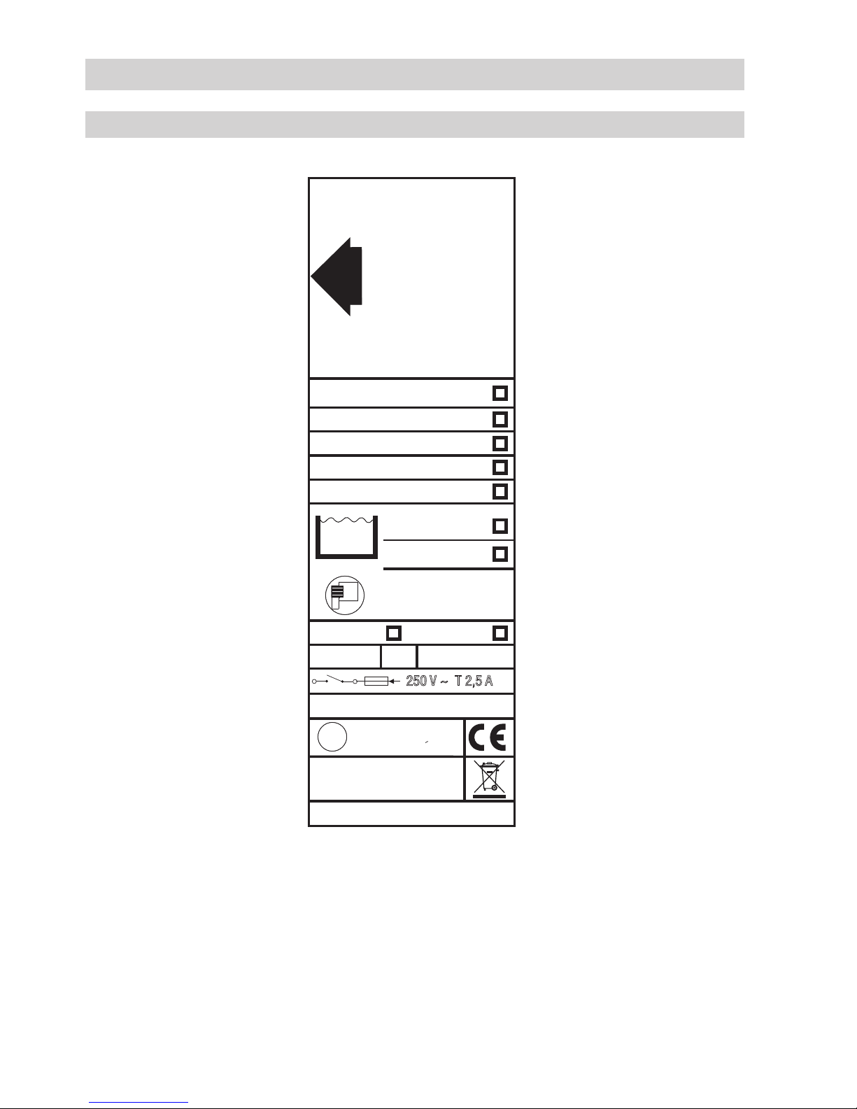
Name plate / marking .............................................................................................................................8
Dimensions.............................................................................................................................................9
Key.......................................................................................................................................................12
Functional Elements
NRGS 11-1, NRGS 16-1, NRGS 16-1S .................................................................................................11
Key.......................................................................................................................................................12
Design
NRGS 11-1, NRGS 16-1, NRGS 16-1S .................................................................................................10
Key.......................................................................................................................................................12

3
NRGS 11-1, NRGS 16-1, NRGS 16-1S ................................................................................................20
Note .....................................................................................................................................................20
Operation
Electrical Connection
NRGS 11-1, NRGS 16-1, NRGS 16-1S ................................................................................................17
Wiring diagram.....................................................................................................................................17
Fill control.............................................................................................................................................18
Discharge control..................................................................................................................................18
Attention...............................................................................................................................................18
Tools.....................................................................................................................................................18
Basic Settings
Factory setting .....................................................................................................................................19
Selecting the measuring range .............................................................................................................19
Attention...............................................................................................................................................19
Tools.....................................................................................................................................................19
Danger .................................................................................................................................................20
Checking electrical connection .............................................................................................................20
Checking correlation of switching functions ..........................................................................................20
Applying mains voltage ........................................................................................................................20
Commissioning Procedure
Contents continued
Fault finding list for troubleshooting......................................................................................................21
Troubleshooting
Page
Exchanging the electronic insert, removing the compact system
Danger .................................................................................................................................................22
Replacing electronic insert....................................................................................................................22
Removing and disposing of the compact system...................................................................................22
Note .....................................................................................................................................................22

4
Important Notes
Usage for the intended purpose
Use compact system for level monitoring NRGS 11-1, NRGS 16-1 and NRGS 16-1S only for level
indication in electrically conductive liquids.
Safety note
The equipment must only be installed and commissioned by qualified and competent staff.
Retrofitting and maintenance work must only be performed by adequately trained persons who
have a recognised level of competence.
Danger
When loosening the equipment steam or hot water might escape!
This presents the risk of severe scalding all over the body!
Do not remove the equipment unless the boiler pressure is verified to be 0 bar.
The terminal strip of the NRGS 11-1, NRGS 16-1, NRGS 16-1S is live during operation.
This presents the danger of electric shock!
Cut off power supply before mounting or removing the housing cover!
ATEX (Atmosphère Explosible)
According to the European Directive 2014/34/EU the equipment must not be used in potentially explo-
sive areas.
Attention
The name plate specifies the technical features of the equipment. Do not commission or
operate any item of equipment that does not bear its specific name plate.
LV (Low Voltage) Directive and EMC (Electromagnetic Compatibility)
The equipment meets the requirements of the Low Voltage Directive 2014/35/EU and the
EMC Directive 2014/30/EU.
Note on the Declaration of Conformity / Declaration by the Manufacturer
For details on the conformity of our equipment according to the European Directives see our Declaration
of Conformity or our Declaration of Manufacturer.
The current Declaration of Conformity / Declaration of Manufacturer are available in the Internet under
www.gestra./de/documents or can be requested from us.

5
Explanatory Notes
Scope of supply
Function
NRGS 111
1 Compact system NRGS 11-1, PN 6
1 Joint ring D 33 x 39 DIN 7603-1.4301
1 Installation manual
NRGS 161
1 Compact system NRGS 16-1, PN 40
1 Joint ring D 33 x 39 DIN 7603-1.4301
1 Installation manual
NRGS 16 1 S
1 Compact system NRGS 16-1 S (for marine applications)
1 Flanged DN 50, PN 40, DIN 2635
1 Installation manual
Description
The compact system NRGS 11-1, NRGS 16-1, NRGS 16-1 S works according to the conductivity
measurement system.
With the NRGS 11-1, NRGS 16-1 and NRGS 16-1S a maximum of 4 levels can be signalled in
conductive liquids:
4 levels with one switchpoint each
high-level alarm, low-level alarm, pump ON, pump OFF with one switchpoint each.
The compact system has a level controller integrated in the terminal box for the control of all functions.
External switchgear is therefore not required.
The conductivity of the liquid is used to signal the liquid level. Some liquids are conductive, which
means that they allow an electric current to flow through them. For the safe functioning of this
device a minimum conductivity of the liquid to be monitored is required
The conductivity measurement method can detect two conditions: electrode tip submerged or
exposed, meaning switchpoint reached or not reached.
Before installation, the length of the electrode tips must be cut to the required switching levels,
e. g. for high-level / low-level alarm, controlling of a valve or pump.
Design
NRGS 111, NRGS 161:
Screwed design 1" BSP, DIN ISO 228. Fig. 1
NRGS 16 1 S:
Flanged design for marine application DN 50, PN 40, DIN 2635. Fig. 2

6
NRGS 111, NRGS 161, NRGS 161S
Type approval
NRGS 11-1: TÜV · WR · 11-388
NRGS 16-1: TÜV · WB · 11-388
NRGS 16-1 S: GL 99250-96 HH
LR 98/20075
RINA No ELE/30298/1
Operating pressure
NRGS 11-1: 6 bar g at 159 °C
NRGS 16-1: 32 bar g at 238 °C
NRGS 16-1 S: 32 bar g at 238 °C
Mechanical connection
Screwed 1", DIN ISO 228
Flanged DN 50, PN 40, DIN 2635
Materials
Body 3.2161 G AlSi8Cu3
Sheath 1.4301 X5 CrNi18-10
Flange 1.0460 C 22.8
Measuring electrodes 1.4571 CrNiMoTi17-12-2
Electrode insulation PTFE
Spacer disk PTFE
Lengths available
1500 mm
1000 mm
1500 mm
Mains voltage
230 V +/– 10%, 50/60 Hz
115 V +/– 10%, 50/60 Hz
124 V +/– 10%, 50/60 Hz (optional)
Power consumption
5 VA
Fuse
Thermal fuse, T
max = 102 °C
Sensitivity of response
Range 1: 10 µS/cm
Range 2: 0,5 µS/cm
Electrode voltage
10 VVS
Output
Four volt-free relay contacts.
Max. contact rating with switching voltages of 24 V, 115 V and 230 V AC: resistive 4 A,
inductive 0.75 A at cos ϕ 0.5.
Max. contact rating with a switching voltage of 24 V DC: 4 A.
Contact material: silver, hard-gold plated.
Technical Data

7
NRGS 111, NRGS 161, NRGS 161S continued
Energizing/deenergizing delay
3 sec., factory set
Indicators and adjustors
4 red LEDs for signalling “electrode submerged”, “output relay energized”.
1 four-pole code switch for changing sensitivity.
Cable entry
Cable gland with integral cable clamp
M 16 (2) (PG 9)
M 20 (1) (PG 16)
Protection
IP 65 to DIN EN 60529
Max. admissible ambient temperature
70 °C
Weight
NRGS 11-1: approx. 1.8 kg
NRGS 16-1: approx. 1.8 kg
NRGS 16-1 S: approx. 2.5 kg
Technical Data continued

8
Technical Data continued
Name plate / marking
Schrift : schwarz
Schildgrund : metallic-silber
selbstklebende Folie Typ 3M FES 706 wetterfest
24 V
PN 40
PN 40
PN 6
IP 65
Pmax
Tmax
NRGS 16 - 1
NRGS 16 - 1s
NRGS 11 - 1
115/230 V
G 1 1.4571
DN 50 1.4571/1.0460
250 V ~ T 2,5 A
Before removing cover
isolate from power supplies
See installation instructions
Avant d'ouvrir le couvercle
dèconnecter complètement
l'appareil
Voir instructions de
montage
6 bar ( 87psi)
159°C (318°F)
32 bar (464psi)
238°C (460°F)
Tamb
70°C
(158°F)
GL 99250-96 HH
Vor Öffnen des Deckels
Gerät freischalten!
Betriebsanleitung
beachten
50 / 60 Hz 5VA 0,5 / 10 µS/cm
GESTRA AG
Münchener Str. 77
D-28215 Bremen
TÜV . WR . xx-388
Mat-Nr.:
CC
UU
DD
Freigabe
Norm geprüft
Geprüft
Gezeichnet
Dat. geschützt
Maßstab
Für diese Zeichnung
behalten wir uns
alle Recfhte vor
Freimaßtoleranzen
ISO 2768 mittel 1:1
Nr. Änderung Datum Geänd. Daten Mittlg-Nr.Freig.
Datum Name
Nr.
Ersatz für: Ersetzt durch:
Datei - NR.: 4-387040.CDR
4-387040-08
Typenschild VG
NRGS 11-1
NRGS 16-1
NRGS 16-1s
97-01-15
Semken
97-01-15
97-01-15
97-10-02
Laupichler
Hansen
11547
12358
9817
Jac.
Paul
Przy.
Laupich.
Laupich.
Laupich.Hansen
Hansen
Hansen
06-01-15
12-01-17
98.08.27
Die TÜV-Nr. wurde erneuert; Mülltonne hinzugefügt, Temeraturen (*F) angepasst
TÜV.WRB. 06-388 in TÜV.WR. 11-388 geändert, Mat-Nr. hinzugefügt.
Die Bedruckung geändert
07
08
03
04 Typenschild wurde durch die NRGS16-1s-Angabe erweitert und durch die Schutzrechtangabe ergänzt. 98-11-10 Przy. Laupich. 9853
05
06
TÜV-Rheinland Logo entfernt
Die TÜV-Nr. wurde erneuert .
00-03-16
01-09-04
Win.
Przy.
10091
10524
Laupich.
Laupich.
43 21
A
B
C
D
135
43

9
Technical Data continued
Dimensions
31
GESTRA SteamSystems
GESTRA
NRGS 16-1
Fig. 1NRGS 11-1, NRGS 16-1 Fig. 2 NRGS 16-1S
∅ 42
173
173
140
338
140
62436, 936, 1436
500, 1000, 1500 338
b = 70 b = 70
B
∅ 42

10
Design
NRGS 111, NRGS 161, NRGS 161S
Fig. 5Fig. 3
Fig. 4
N8
50
65 –70
≥14
∅ 40
1", DIN 228
N 10
0.5
A
D
B
D
C

11
Functional Elements
NRGS 111, NRGS 161, NRGS 161S
Fig. 6
Fig. 7
E F G
1 3 5
2 4
L
KJ
IH

12
Technical Data / Design / Functional Elements
Key
AElectrode thread 1", DIN 228
BSeating surface
CJoint ring D 33 x 39 DIN 7603 -1.4301
DFlange DN 50, PN 40, DIN 2635
EHousing screws M4
FCable entry M 16 (PG 9) / M 20 (PG 16)
GHousing cover
HTerminal strip
IPE connection
JTerminal strip for testing
KThermal fuse T
max 102 °C
LPlug
1LED “Low-level alarm”
2LED “Pump ON”
3LED “Pump OFF”
4LED “High-level alarm”
5Code switch for measuring range

13
5. Check seating surfaces of threads or flange provided on vessel or boiler standpipe. Fig. 5
6. Place joint ring Conto seating surface of the threaded standpipe or flange. Fig. 5
Use only the joint ring (of stainless steel 1.4301, D 33 x 39 DIN 7603) supplied with the electrode.
7. Apply a light smear of silicone grease (e. g. Molykote® 111) to electrode thread A.
8. Screw level electrode into threads or flange provided on vessel and tighten with a 41 mm open-end
spanner. The torque required when cold is 140 Nm.
Installation
NRGS 111, NRGS 161, NRGS 161 S
NRGS 111, NRGS 161
1. Determine required measuring lengths of electrode tips and enter data in table “Functions”. Fig. 3
2. Cut electrode tips 1 , 2 , 3 and 4 accordingly.
3. Deburr faces of electode tips.
4. Strip off 50 mm of PTFE insulation from the ends of the electrode tips.
Molykote® 11 1 is a registered trademark of DOW Corning Corp., Midland Michigan, USA
Table Functions
NRGS 16 1 S
9. Check seating surfaces and place joint ring onto the connecting standpipe.
10. Put flange Dwith level electrode onto connecting standpipe and secure with bolts.
Tighten bolts in diagonally opposite pairs. Fig. 4
Please enter function and length.
Function Function Electrode tip Length [mm]
e. g. first low-level alarm 1
e. g. feed pump ON 2
e. g. feed pump OFF 3
e. g. high level alarm 4

14
Installation continued
Attention
The seating surfaces of the standpipe or the flange provided on the vessel must be
accurately machined, see Fig. 5
Do not bend electrode tip when mounting.
Do not lag electrode body above the hexgonal section.
Note
For the approval of the boiler standpipe the relevant regulations must be considered.
Refer to page 15 for four typical installation examples.
Tools
Open-end spanner A. F. 41, DIN 894
Bolt cutter
Hacksaw
Flat file, medium cut

15
Installation continued
Examples of installation
1
DN 100
Fig. 10
∅20 20
24,5 24,5
∅20
Fig. 8 Fig. 9
DN 50
≤ 90°
DN 50
1"
1"
1" 1"
≥10
∅20
≤ 90°
≤90°
∅ 20
∅
20
20
≥ 10
∅20
DN 20
DN 20
Fig. 11
≤20
1"
≤20
20
≤1500
Centre distance
2
3
4
6
0
!
5
1
8
0
7
2
9
"
3
5
4
1
5
4
0
2
DN 20
1
2
3
4
6
0
!
5

16
1
Flange PN 40, DN 50, DIN 2527
Flange PN 40, DN 100, DIN 2527
2For the approval of the boiler standpipe with connecting flange the relevant regulations
must be considered.
3Vent hole
4High water (HW)
5Electrode rod d = 5 mm
6Protection tube DN 80
7Protection tube DN 100
8Electrode distance ≥14 mm
9Electrode distance ≥40 mm
0Low water (LW)
!Reducer DIN 2616, part 2 K-88.9 x 3.2-42.4 x 2.6 W
"Reducer DIN 2616, part 2 K-114.3 x 3.6-48.3 x2.9 W
Key
Installation continued

17
Electrical Connection
Flexible multi-core control cable can be used for wiring, min. conductor size 1.5 mm2.
1. Unscrew screws Eand take off housing cover G. Fig. 6
2. Unscrew union nuts of cable entries F.
The terminal box can be turned through +/– 180°.
3. Loosen nut Lwith 17 mm open-end spanner but do not remove! Fig. 7
4. Turn electrode terminal box into desired direction (+/– 180°).
5. Tighten plug Lslightly.
6. Remove terminal strips Hfrom circuit board.
7. Connect terminal strip according to wiring diagram, establish PE connection I.
8. Attach terminal strip.
9. Mount housing cover G, fasten screws Eand install cable entry F.
NRGS 111, NRGS 161, NRGS 161 S
Wiring diagram
Fig. 12
Mains

18
Fill control
Discharge control
Fig. 13
Fig. 14
Electrical Connection continued
Tools
Attention
Screwdriver for cross head screws, size 1
Screwdriver for slotted screws, size 2.5, completely insulated according to VDE 0680
Open-end spanner A. F. 17, DIN 894
Provide supply cables with a slow-blow fuse 250 mA.
The connection of the switchpoints 2and 3must be effected on site
(pump contactor, auxiliary relay)!
Mains
Mains
LW

19
Basic Settings
The measuring range can be switch-selected between ≥ 0.5 µS/cm and ≥ 10 µS/cm by means of the
code switch 5:
1. Undo screws Eof the electrode terminal box and remove housing cover. Fig. 6
Code switch 1 – 4 OFF Measuring range ≥0.5 µS/cm.
Code switch 1 – 4 ON Measuring range ≥10 µS/cm.
2. Replace cover Gand fasten screws E.
Factory setting
The equipment features the following factory set default value:
Measuring range ≥10 µS/cm
Selecting the measuring range
Attention
Screwdriver for cross head screws, size 1
Screwdriver for slotted screws, size 2.5, completely insulated according to VDE 0680
Do not damage the electronic components when setting the code switch!
Tools

20
1. Apply mains voltage. Check that all functions of the respective switchpoints work correctly.
LEDs 1, 2, 3, 4are provided for visual check of switchpoints. Fig. 7
To check the correct functioning of the LEDs 1, 2, 3, 4remove the housing cover G.See section
“Electrical Connection”.
Commissioning Procedure
Danger
1. Check whether the system has been wired according to the wiring diagram. Fig. 12
2. Check whether the mains supply is in accordance with the wiring of the equipment.
The terminal strip of the NRGS 11-1, NRGS 16-1, NRGS 16 -1S is live during operation.
This presents the danger of electric shock!
Cut off power supply before mounting or removing the housing cover!
Checking electrical connection
Applying mains voltage
1. Check whether the designated switchpoints (i. e. switching functions) have been correctly allocated
to the individual electrode tips. See table “Functions” page 13.
Checking assignation of switching functions
Operation
For operation in (pressurized) hot-water or steam boilers to TRD 401, TRD 602, TRD 604, EN 12952,
EN 12953 or according to national directives or regulations of the classification society.
NRGS 111, NRGS 161, NRGS 111S
Note
To analyse and eliminate malfunctions refer to section “Fault finding list for trouble-
shooting” on page 21.
This manual suits for next models
2
Table of contents
Other GESTRA Kitchen Appliance manuals
Popular Kitchen Appliance manuals by other brands

Siemens
Siemens CD634GA 0 Series User manual and installation instructions

CENTRAL RESTAURANT PRODUCTS
CENTRAL RESTAURANT PRODUCTS 69K-143 Service, installation and care manual

Trebs
Trebs 9920 manual

Mychef
Mychef iSENSOR MVPB1640 product manual

Miele
Miele EVS 6114 Operating and installation instructions

Vitek
Vitek VT-3657 ST Manual instruction