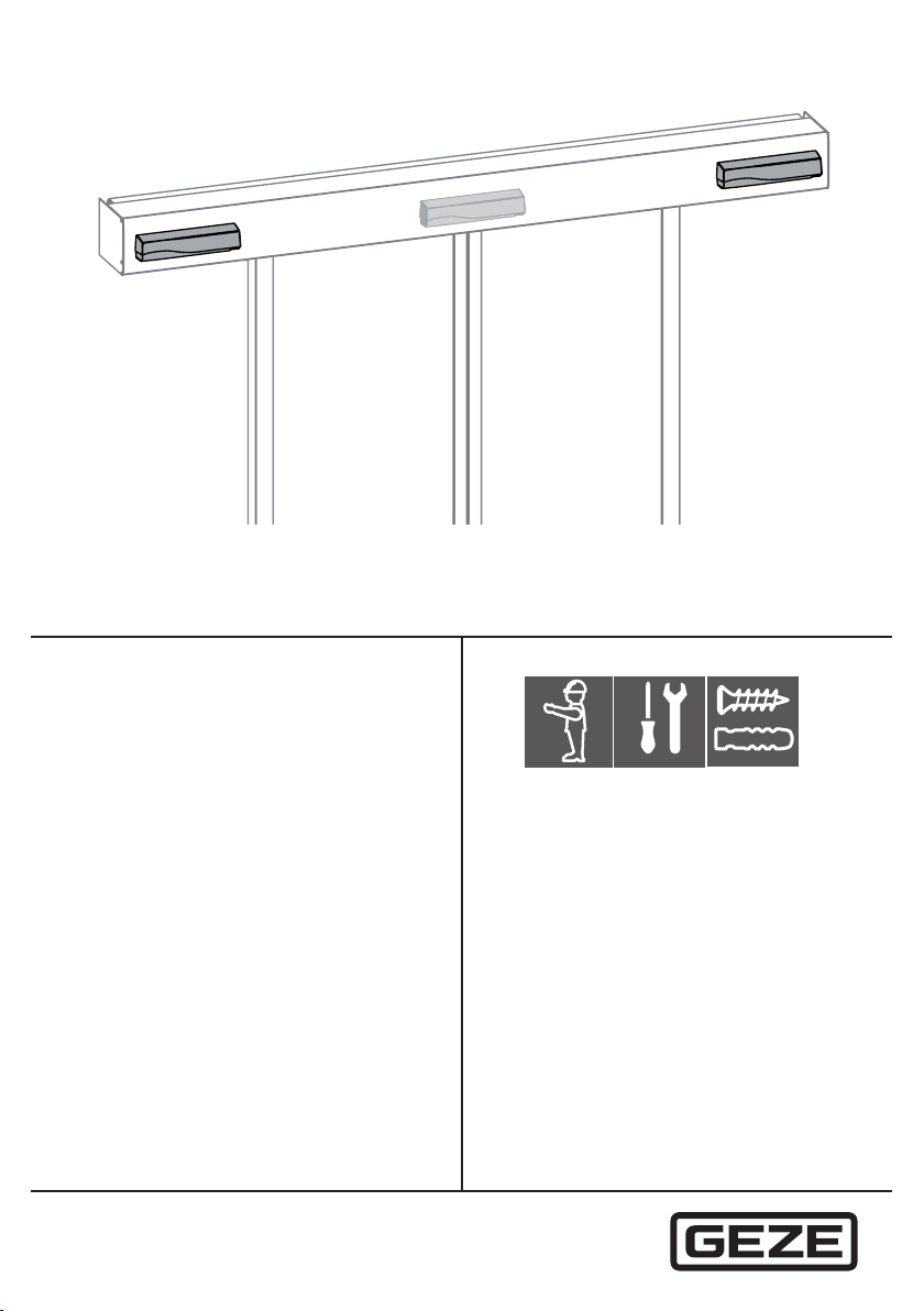
GEZE GC 339+ User manual

GC 339+
203883-00
47.0643 v2 - 10.2022

GC 339+
2
Contents
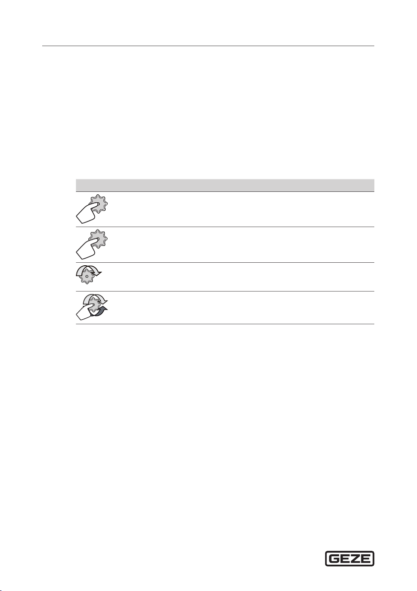
Symbols and illustrations .................................................................................4
Abbreviations .......................................................................................................4
Product liability....................................................................................................4
1 Safety ..........................................................................................................5
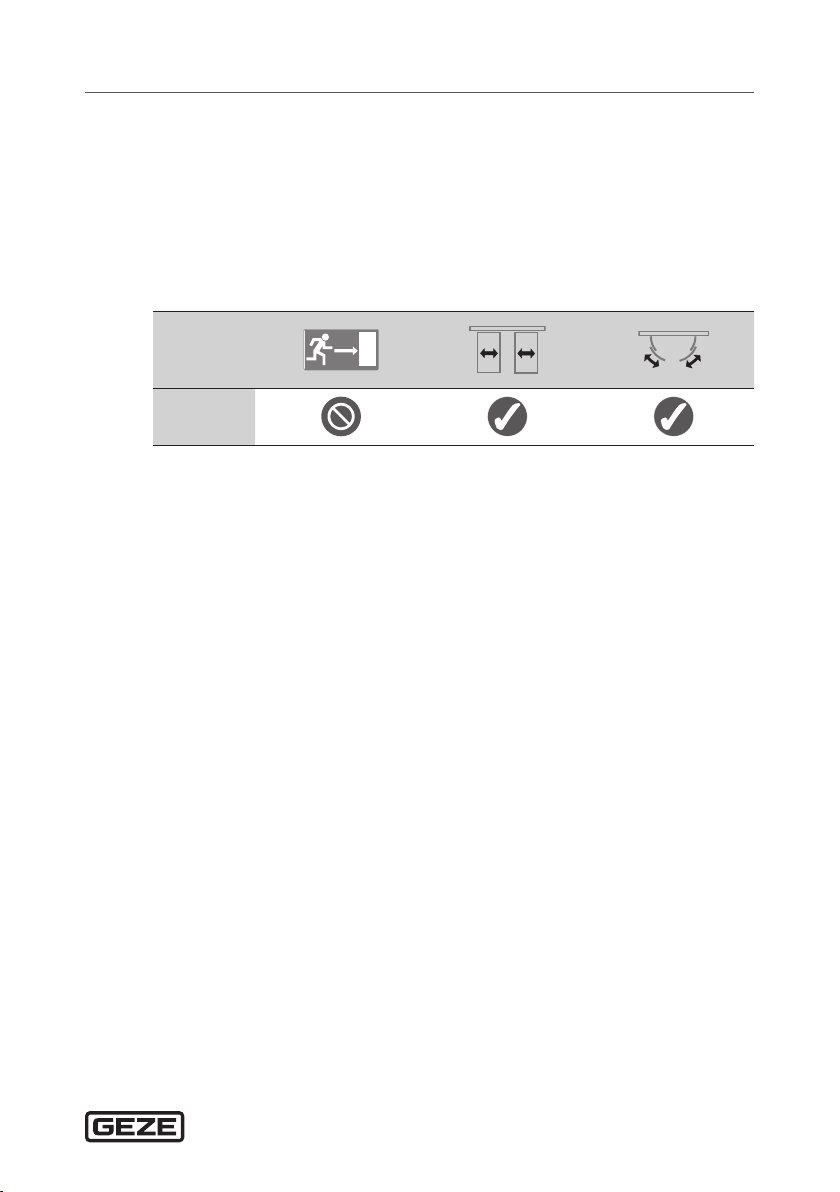
1.1 Intended use........................................................................................................................5
1.2 Safety notes ........................................................................................................................5
1.3 Safety-conscious working..............................................................................................6
1.4 Environmentally conscious working ..........................................................................6
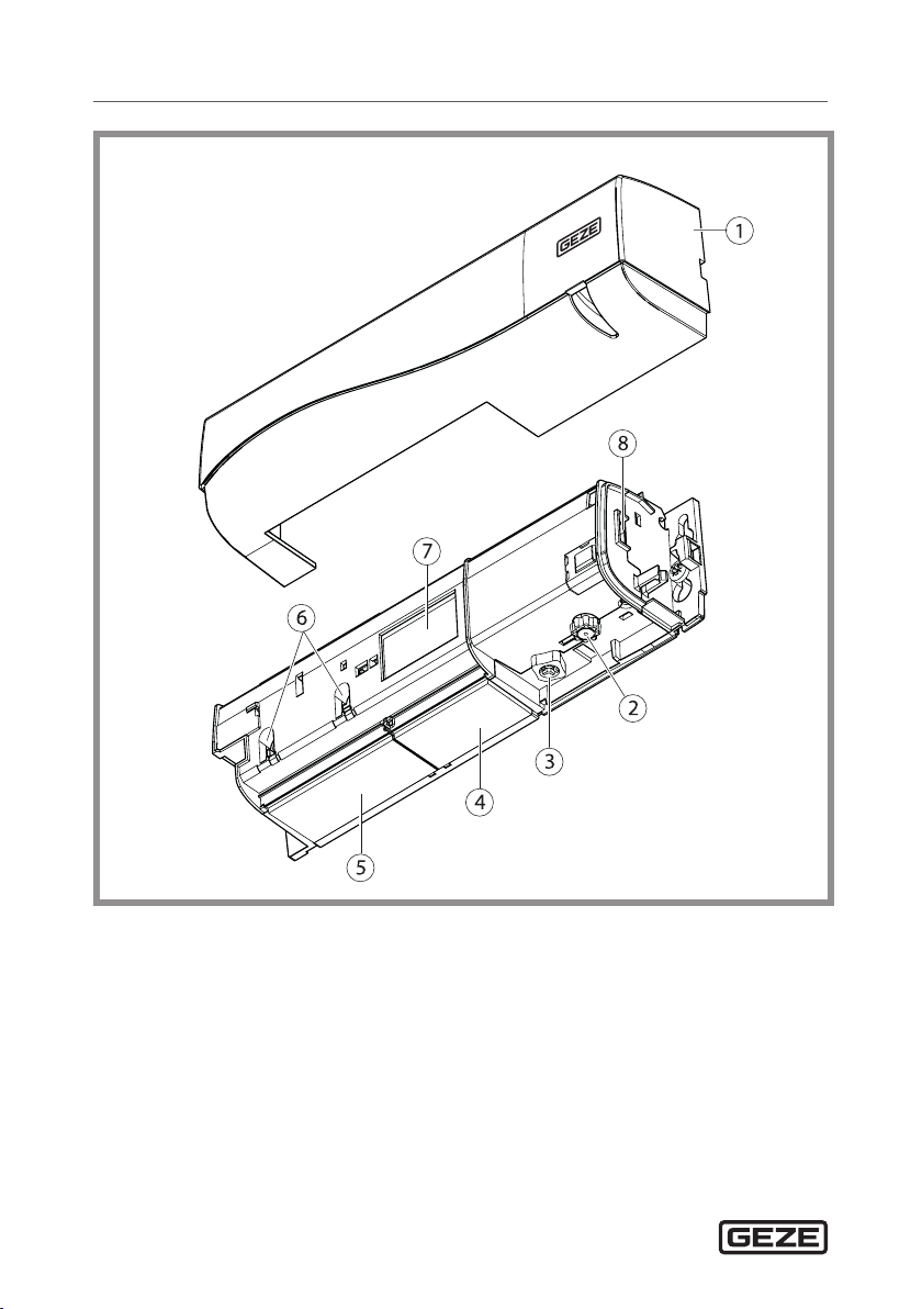
2 Description................................................................................................7
2.1 Scope of delivery ...............................................................................................................9
3 Work to be done before installation................................................9
3.1 Installing the drive.............................................................................................................9
3.2 Safety sensor system..................................................................................................... 10
4 Installation...............................................................................................11
4.1 Installation without accessories.................................................................................11
4.2 Installation with ceiling installation kit .................................................................. 12
4.3 Installation with mounting bracket ......................................................................... 14
4.4 Installation with weather hood ................................................................................. 15
4.5 Cabling ............................................................................................................................... 16
5 Retrot......................................................................................................17
6 Commissioning.....................................................................................17
6.1 Protection area .................................................................................................................17
6.2 Settings .............................................................................................................................. 19
6.3 Teach-in.............................................................................................................................. 19
7 Conguration possibilities.................................................................20
7.1 Using the LCD menu...................................................................................................... 20
7.1.1 Display during normal function................................................................................ 20
7.1.2 Menu navigation............................................................................................................. 20
7.1.3 Changing ZIP code......................................................................................................... 20
7.1.4 Changing and storing values ..................................................................................... 21
7.1.5 Checking values using the remote control........................................................... 21
8 Settings ....................................................................................................21
8.1 Presettings ........................................................................................................................ 21
9 Last installation steps..........................................................................24
10 Further installation situations ..........................................................25
Translation of the original operating instructions for device version 0600

3
GC 339+
10.1 Single leaf installation and separate activation .................................................. 25
10.2 Wall mounting ................................................................................................................. 27
11 Maintenance...........................................................................................27
12 Fault messages and troubleshooting............................................28
13 Technical data ........................................................................................30
14 Accessories / spare parts....................................................................31

GC 339+
4
Symbols and illustrations
Warning notices
In these instructions, warning notices are used to warn against material
damage and injuries.
XAlways read and observe these warning notices.
XObserve all measures marked with the warning symbol and warning word.
Explanation of symbols
In these instructions, the following symbols are used for setting and cong-
uration work:
Symbol Explanation
Press push button
2x
Press push button 2×
Turn push button
Press and turn push button
Abbreviations
FR Escape and rescue routes
IR Infrared
IR Active infrared
RAD Radar
LCD Liquid Crystal Display
Main closing edge /
secondary closing edge
Main closing edge / secondary closing
edge
Product liability
In compliance with the liability of the manufacturer for his products as
dened in the German “Product Liability Act”, compliance with the infor-
mation contained in this brochure (product information and intended use,
misuse, product performance, product maintenance, obligations to provide
information and instructions) must be ensured. Failure to comply releases
the manufacturer from his statutory liability.

5
SafetyGC 339+
1 Safety
1.1 Intended use
The GC339+ safety sensor may only be used to protect automatic sliding
doors and curved sliding doors with GEZE drives. The minimum object size
corresponds to the reference object CA according to DIN 18650 or 16005
both upright and lying down. The sensor can be used to secure automatic
sliding doors against impact and trapping of the human body.
GC339
1.2 Safety notes
àThe prescribed mounting, maintenance and repair work must be per-
formed by personnel authorised by GEZE. Any attempts at repairs by
unauthorised personnel cancel the factory guarantee.
àThe device may only be operated with safety extra-low voltage (SELV)
with electrically protective separation.
àThe country-specic laws and regulations are to be observed during
safety-related tests.
àMake sure that the cover of the drive is tted correctly and earthed.
àIf unauthorised changes are made to the system, GEZE cannot be held li-
able in any way whatsoever for any resulting damage, and the statement
of approval for use in escape and rescue routes is no longer valid.
àGEZE does not accept any warranty for combinations with third-party
products.
àOnly original GEZE parts may be used for repair and maintenance work.
àObserve the latest versions of guidelines, standards and country-specic
regulations, in particular:
àASR A1.7 “Doors and gates”
àDIN 18650 “Building hardware – Powered pedestrian doors”
àDIN EN 16005 “Power operated pedestrian doorsets – Safety in use –
Requirements and test methods”
àAccident-prevention regulations, especially BGV A1 “General regula-
tions” and BGV A2 “Electrical installations and equipment”.

Safety GC 339+
6
àThe risk assessment and installation of the sensor and the door system in
compliance with national and international regulations and door safety
standards are the responsibility of the door manufacturer.
àThe manufacturer cannot accept any responsibility for defective installa-
tion or setting of the sensor.
àBefore leaving the installation, test the sensor for correct function.
àAny uses of the device other than those described in this manual do not
correspond to the approved purpose and cannot be guaranteed by the
manufacturer.
1.3 Safety-conscious working
àSecure workplace against unauthorised entry.
àWatch the swivelling range of long system parts.
àSecure the cover/drive panels against falling.
àAttach safety stickers to glass leaves.
àDanger of injury with opened drive. Hair, clothing, cables, etc. can be
drawn in by rotating parts.
àDanger of injury caused by unsecured crushing, impact, drawing-in or
shearing spots.
àDanger of injury due to glass breakage.
àDanger of injury due to sharp edges in the drive.
àDanger of injury by freely moving parts during installation.
1.4 Environmentally conscious working
àWhen disposing of the door system, separate the dierent materials and
have them recycled.

7
DescriptionGC 339+
2 Description
The GC339+ safety sensor has an infrared eld for protection.
The mutual inuence of several sensor systems with hazardous eect
is not possible. Unintentional stop signals are possible where detectors
are mounted next to one another, since their infrared measuring ranges
overlap and each sensor could activate the other. This inuence is kept to
aminimum by dierent frequency settings.
Variant GC339+
Black 203858
According to RAL 203859

Description GC 339+
8
1 Cover
2 Setting push button (grey)
3 Button for setting the angle of
the IR curtain (red)
4 IR lens (transmitter)
5 IR lens (interface)
6 Width adjustment of the IR
curtain
7 LCD
8 Main connector

9
Work to be done before installationGC 339+
2.1 Scope of delivery
3 Work to be done before installation
3.1 Installing the drive
XMake sure that the cover of the drive is tted correctly and earthed.

Work to be done before installation GC 339+
10
3.2 Safety sensor system
One combined detector per passage direction is installed on automatic
sliding doors. The GC 339+ safety sensor may be required in addition for
larger opening widths.
For escape and rescue routes:
àuse protective door leaf if necessary. Heed standards.
GC 363+ R
GC 363+ R
GC 339+
GC 339+
GC 363+ R
GC 363+ SF

11
InstallationGC 339+
4 Installation
4.1 Installation without accessories
XAvoid extreme vibrations.
XDo not cover the sensor.
XKeep away from uorescent lamps.
XKeep away from moving objects.
XAvoid highly reective objects in the infrared range.
XKeep a distance of at least 150 mm away from lights, signs or hot air
curtains.
1
2

Installation GC 339+
12
4.2 Installation with ceiling installation kit
68 × 293 mm
53 × 244 mm
1
2
3
Ceiling installation kit Ceiling installation kit, short

13
InstallationGC 339+
1
1
click
3
3
4
4
4
1
1
click
5
click
6

Installation GC 339+
14
4.3 Installation with mounting bracket
DIN 7981 8 × ½“
1
1
1
3
2

15
InstallationGC 339+
4.4 Installation with weather hood
1
1
2
2
2
2
3
3
4
4

Installation GC 339+
16
4.5 Cabling
XHeed wiring diagrams for the sliding door drives.
1
GC339+
GND
1
4 24Vsw
11 SIS1
1 GND
4 24Vsw
10 TST
SIS1
1
GND
4
24Vsw
1 GND
4
24Vsw
10 TST
12 SIS2
or
110 mA
GC 339+
COM
+
BK
RD
PK
PK
BU
BU
YE
YE
SIS2
1
2
1 IR curtain
2 Test
When activated, the output of the GC 339+ is opened (GND applied to the
SIO input).
XSet the type of contact for SIO 1 and SIS 2 to “normally closed contact”.
XTest the sensor with GND.
For compliance with EN16005 and DIN18650, the test output of the door
control must be wired and the sensor tested.

17
RetrotGC 339+
5 Retrot
GND
1
4 24Vsw
11 SIS1
1 GND
4 24Vsw
10 TST
SIS1
1 GND
4 24Vsw
1 GND
4 24Vsw
10 TST
12 SIS2
or
110 mA
GC 339
COM
+
BN
GN
GY
PK
BU
RD
WH
YE
SIS2
1
2
GND
1
4 24Vsw
11 SIS1
1 GND
4 24Vsw
10 TST
SIS1
1 GND
4 24Vsw
1 GND
4 24Vsw
10 TST
12 SIS2
or
110 mA
GC 339+
COM
+
BK
RD
PK
PK
BU
BU
YE
YE
SIS2
1
2
6 Commissioning
6.1 Protection area
The position of the IR curtain in relation to the door can be checked using
a spot nder.

Commissioning GC 339+
18
XActivate 4 visible
spots.*
XAdjust the tilt angle of the active
infrared detector.
Yellow LED is ashing
on spot nder :
Alignment correct.
2x
max. 9 cm
max. 20 cm
* Visibility depends on the environmental conditions.
àTest the width of the required area using a piece of paper (DIN A4), since
the spot nder detects over the whole emission area.

19
CommissioningGC 339+
XTesting the emission area.
àThe “IR: width” parameter must be set identically (see chapter 8).
àThe complete NSK of the door must be covered.
XSet additional IR:Width parameters.
Standard-conform sensor setting according to DIN 18650 / EN 16005
Installation height Detection width DIN 18650 / EN 16005
2.00 m
2.20 m
2.50 m
3.00 m
3.50 m
2.00 m
2.20 m
2.50 m
2.50 m / 3.00 m
2.50 m / 3.00 m
6.2 Settings
XCongure the sensor using LCD or remote control (see chapters 7 and 8).
6.3 Teach-in
XBefore starting teach-in, move out of the infrared eld.
XBefore leaving the installation, test the correct sensor installation.

Conguration possibilities GC 339+
20
Teach-in 2 sec.
Teach-in with door movement +4 sec.
0
7 Conguration possibilities
7.1 Using the LCD menu
7.1.1 Display during normal function
Opening impulse Protection Image shown negative
= active exit
Set contrast
7.1. 2 Menu navigation
Password
XXXX
English
Deutsch
Français Back
More
Back
More
Pre-setting
Enter pass-
word, if set
7.1. 3 Changing ZIP code
Back
Table of contents