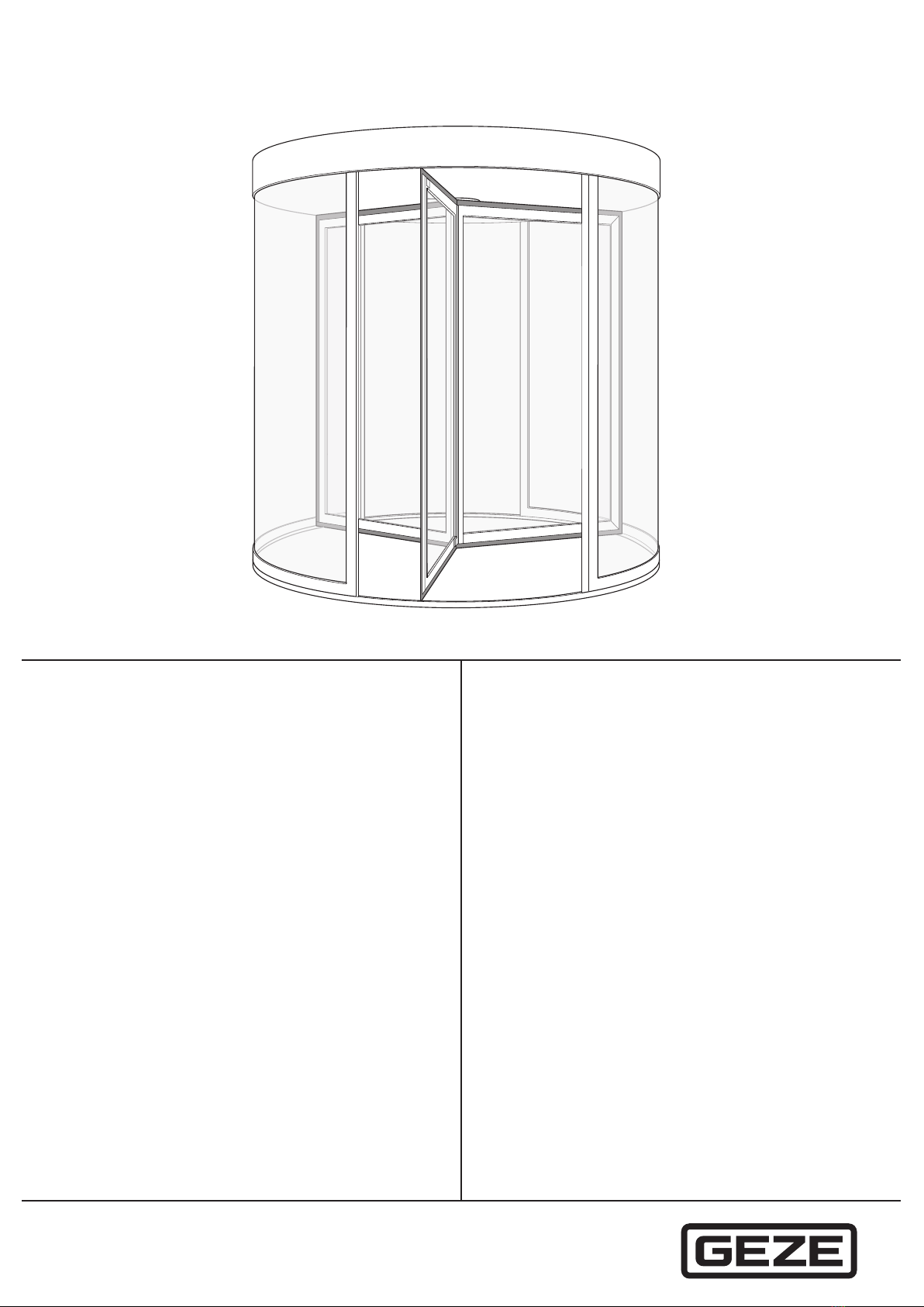
Revolving door TSA 325 NT
2
Table of contents
Symbols and illustrations ..................................................................................................................................................3
Product liability.....................................................................................................................................................................3
1 Security ......................................................................................................................................................................3
1.1 Intended use.......................................................................................................................................................................................................3
1.2 Safety instructions ...........................................................................................................................................................................................4
1.3 Safety conscious working..............................................................................................................................................................................4
1.4 Inspection of the installed system .............................................................................................................................................................5
1.5 Environmentally conscious working .........................................................................................................................................................5
2 Tools and aids ...........................................................................................................................................................5
2.1 General tool set.................................................................................................................................................................................................5
2.2 Special tools........................................................................................................................................................................................................5
2.3 Consumables......................................................................................................................................................................................................6
3 Structure .....................................................................................................................................................................7
4 Installation..................................................................................................................................................................8
4.1 Preparations to be made on site.................................................................................................................................................................8
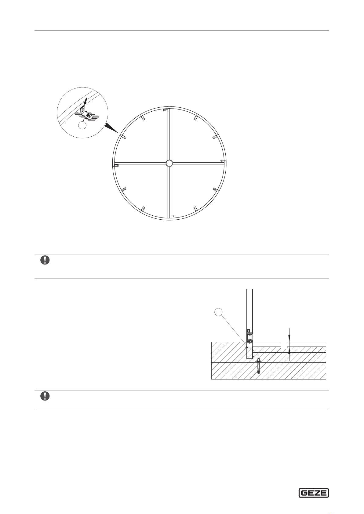
4.2 Mounting the revolving door TSA 325 NT...............................................................................................................................................8
4.3 Mounting switch contact strips on the leaves.................................................................................................................................... 22
4.4 Connect the GEZE ST220 diagnostic device/Use GEZEconnects ................................................................................................ 23
4.5 Mount the ceiling panel.............................................................................................................................................................................. 24
4.6 Check list for commissioning and service ........................................................................................................................................... 27
5 Options..................................................................................................................................................................... 28
5.1 Automatic locking system.......................................................................................................................................................................... 28
5.2 Revolving doors with breakout function.............................................................................................................................................. 33
5.3 External night time closer (automatic and manual)..........................................................................................................................41
5.4 Open position monitoring......................................................................................................................................................................... 43
5.5 General installation information for NV tooth-belt tension.......................................................................................................... 44
5.6 Revolving door in all-glass version (TSA 325 NT GG) ....................................................................................................................... 50
5.7 Speed limiter unit for TSA 325 NT ............................................................................................................................................................61
6 Revolving door TSA 325 NT RC 2..................................................................................................................... 64
6.1 Assemblies and parts ................................................................................................................................................................................... 64
6.2 Revolving door TSA 325 NT RC 2.............................................................................................................................................................. 65
6.3 Installing revolving door TSA 325 NT RC 2........................................................................................................................................... 68
6.4 Installation information for NV tooth belt tension RC2 .................................................................................................................. 86
6.5 Mounting the turnstile ................................................................................................................................................................................ 87
6.6 Mounting contact strips on the leaves.................................................................................................................................................. 87
6.7 Mount the RC 2 ceiling panel.................................................................................................................................................................... 87
6.8 Check list for commissioning and service ............................................................................................................................................ 94
7 Revolving door TSA 325 NT, 3-leaf.................................................................................................................. 95
7.1 Assemblies and parts ................................................................................................................................................................................... 95
7.2 Night-time closer drive (AINV).................................................................................................................................................................. 96
7.3 Mounting the TSA 325 NT revolving door, 3-leaf .............................................................................................................................. 97
7.4 Installation information for NV tooth-belt tension.........................................................................................................................108
7.5 Mounting the turnstile ..............................................................................................................................................................................108
7.6 Mounting contact strips on the leaves................................................................................................................................................109
7.7 Mount the RC 2 ceiling panel..................................................................................................................................................................109
7.8 Check list for commissioning and service ..........................................................................................................................................109