GFA ELEKTROMATEN FCP03 User manual

10.19
FCP03
Fire Control Panel 03
INSTRUCTIONS


03 Fire Door Control Systems
3
Contents
Fire Control Panel 03 – General Layout ....................................................................................... 4
General Layout o Drives and Controls..................................................................................... 4
Fire Control Panel 03 – Connection Drawings ............................................................................. 5
Fire Control Panel Mains Supply Connections ......................................................................... 5
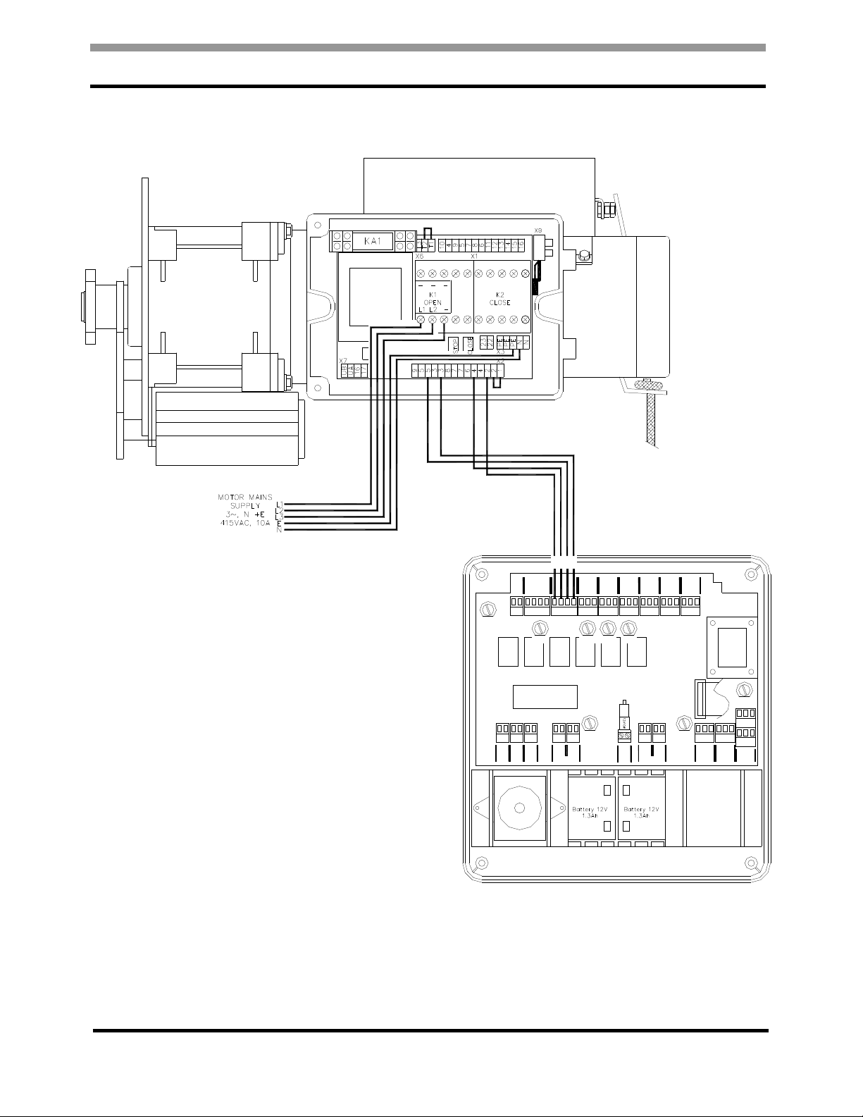
DLA150W Mains Supply and Fire Control Panel Open, Stop, Close Command Wiring ........... 6
DLA250W Mains Supply and Fire Control Panel Open, Stop, Close Command Wiring ........... 7
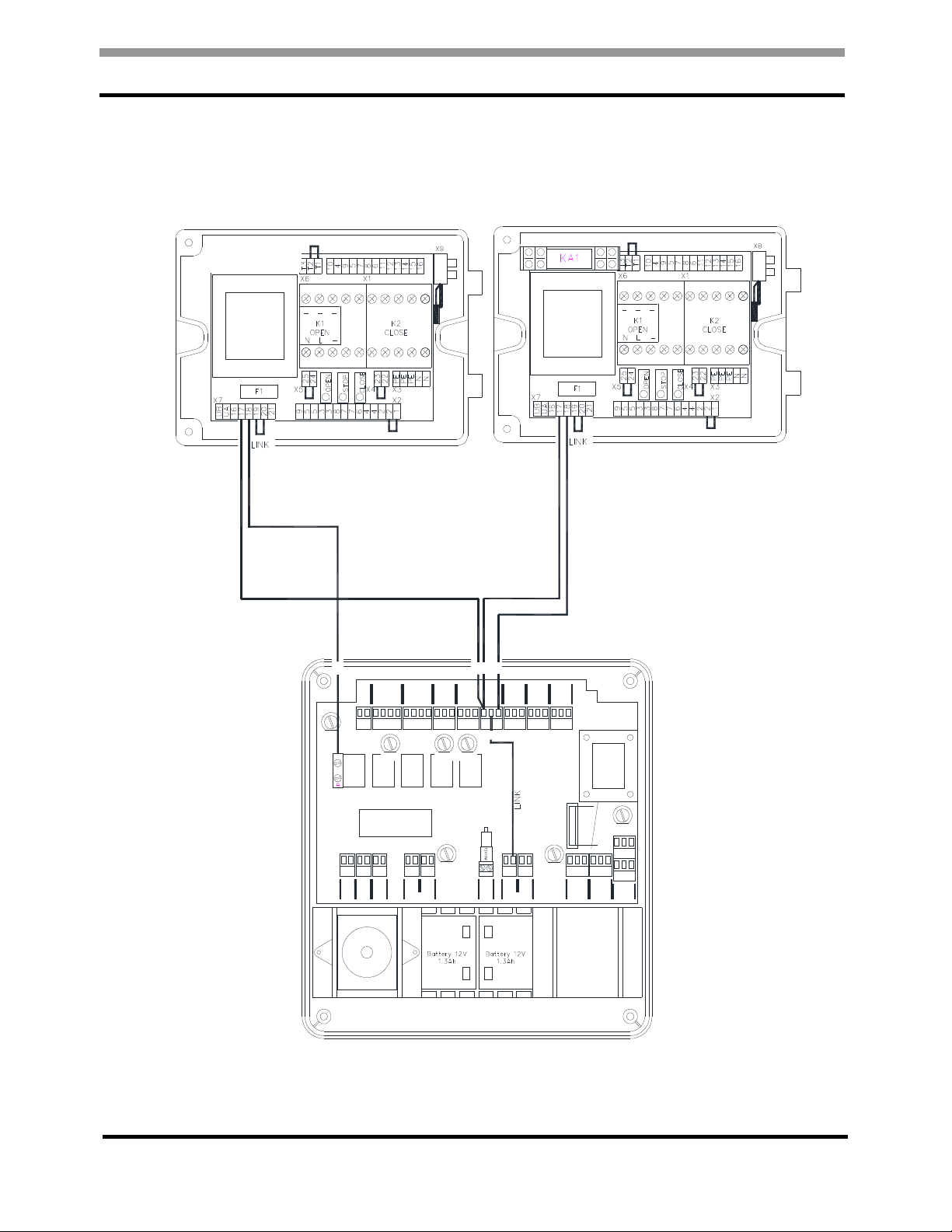
DLA600 and DLA800 Mains Supply and Fire Control Panel Open, Stop, Close Command
Wiring ....................................................................................................................................... 8
DLA150WF, DLA150WM. DLA150WMF and DLA150WA Solenoid Release Connection........ 9
DLA250WF/WM/WMF/WA/WAF, DLA600F/M/A/AF and DLA800F/M/A Solenoid Release
Connection ............................................................................................................................. 10
JESAPZ1-2T – Connecting a Key Switch. .............................................................................. 11
GE3A – Connecting a 3 Push Button Station. ........................................................................ 12
Fire Control Panel 03 – Alarm Connection Drawings ................................................................. 13
Connection o Single Alarm or Full Close Activation ............................................................. 13
Connection o Single Smoke / Heat Detector or Full Close Activation ................................... 14
Connection o Two Smoke / Heat Detectors or Full Close Activation .................................... 14
Fig 6e ..................................................................................................................................... 14
Connection o Dual Alarm Zone 1 and Zone 2 Alarm Full Close activation ............................ 15
Fig 7a
Fig 7b .............................................................................................................. 15
Fig 7c ...................................................................................................................................... 15
Stage Alarm, Zone 1 Alarm Part Close, Zone 2 Alarm Full Close. ......................................... 16
Fire Control Panel 03 – Photo Beam Connection Drawings....................................................... 17
Connection o a Re lective Photo Beam ................................................................................. 17
Connection o a Thru-beam Photo Beam ............................................................................... 18
Fig 9b ..................................................................................................................................... 18
Fire Control Panel 03 – Set Up .................................................................................................. 19
To Enter the FCP03 Set-Up Menus ........................................................................................ 19
Fire Control Panel 03 – Fast Set Tables .................................................................................... 20
Fire Control Panel 03 – Fast Set Drawings ................................................................................ 23
Fast-Set 1 ............................................................................................................................... 23
Fig 11a ................................................................................................................................... 23
Fast-Set 2 ............................................................................................................................... 23
Fig 11b ................................................................................................................................... 23
Fast-Set 3 ............................................................................................................................... 24
Fig 11c .................................................................................................................................... 24
Fast-Set 4 ............................................................................................................................... 24
Fig 11d ................................................................................................................................... 24
Fast-Set 5 ............................................................................................................................... 25
Fig 11e ................................................................................................................................... 25
Fire Control Panel 03 – Engineers Set Up ................................................................................. 26
Description o Functions ......................................................................................................... 26
Fig 12 ..................................................................................................................................... 26
Fire Control Panel 03 – Trouble Shooting .................................................................................. 33
Fire Control Panel 03 – Your Settings ........................................................................................ 34
Fire Control Panel 03 – Replacing the Batteries ........................................................................ 35

03 Fire Door Control Systems
4
Fire Control Panel 03 – General Layout
General Layout of Drives and Controls
Fig 1
WARNING
FIRE
SHUTTER
CLOSING
Guthrie Douglas
Guthrie Douglas
WARNING
FIRE
SHUTTER
CLOSING
Guthrie Douglas

03 Fire Door Control Systems
5
Fire Control Panel 03 – Connection Drawings
Fire Control Panel Mains Su ly Connections
Fig 2
1 2 3 4 56 7 8 9 10 1112 13 141516 171819 20 2122 232425 26 2728
RESET
SC
INPUT
BUTTON
SC
OPEN
STOP
CLOSE
PUSH
INPUT OUTPUT
COMM
STOP
CLOSE
OPEN
MOTOR
CONTROL AUX 1
N/C
C12
N/O
AUX 2
N/C
C13
N/O
SOLENOID
0V
C18
N/O
ZONE 2
SC
INPUT
0V
PEC
SC
INPUT
0V
ZONE 1
SC
INPUT
0V
31322930 3334 3536 3738 4142 4344 4546 47 484950 E N L
515253
EXT
LAMP
- +
EXT
SOUNDER
- +
INT
SOUNDER
- +
EXT 12VDC
- + - +
INT
LAMP
- +
EXT 24VDC
- + - +
BATT 2
+ + -
BATT 1
+ + -
F5.0A
F2
F2.5A
F1
F1.0A
F5
F1.0A
F6
F5.0A
F7
F1.0A
F4
F100mA
F8
F250mA
F3

03 Fire Door Control Systems
6
Fire Control Panel 03 – Connection Drawings
DLA150W Mains Su ly and Fire Control Panel O en, Sto , Close Command Wiring
Fig 3a
1 2 3 4 5 6 7 8 9 10 111213 1415 16 171819 20 2122 232425 262728
RESET
SC
INPUT
BUTTON
SC
OPEN
STOP
CLOSE
PUSH
INPUT
COMM
STOP
CLOSE
OPEN
AUX 1
N/C
C12
N/O
AUX 2
N/C
C13
N/O
SOLENOID
0V
C18
N/O
ZONE 2
SC
INPUT
0V
PEC
SC
INPUT
0V
ZONE 1
SC
INPUT
0V
31322930 3334 3536 3738 4142 4344 4546 47 484950 E N L
515253
EXT
- +
EXT
- +
INT
- +
EXT 12VDC
- + - +
INT
- +
EXT 24VDC
- + - +
BATT 2
+ + -
BATT 1
+ + -
230vAC 50Hz
E N L
F5.0A
F2
F2.5A
F1
F1.0A
F5
F1.0A
F6
F5.0A
F7
F1.0A
F4
F100mA
F8
F250mA
F3

03 Fire Door Control Systems
7
Fire Control Panel 03 – Connection Drawings
DLA250W and DLA500W Mains Su ly and Fire Control Panel O en, Sto , Close
Command Wiring
Fig 3b
1 2 3 4 5 6 7 8 9 10 111213 141516 171819 20 2122 232425 262728
RESET
SC
INPUT
BUTTON
SC
OPEN
STOP
CLOSE
PUSH
INPUT
COMM
STOP
CLOSE
OPEN
AUX 1
N/C
C12
N/O
AUX 2
N/C
C13
N/O
SOLENOID
0V
C18
N/O
ZONE 2
SC
INPUT
0V
PEC
SC
INPUT
0V
ZONE 1
SC
INPUT
0V
31322930 3334 3536 3738 4142 4344 454647 48 4950 E N L
515253
EXT
LAMP
- +
EXT
SOUNDER
- +
INT
SOUNDER
- +
EXT 12VDC
- + - +
INT
LAMP
- +
EXT 24VDC
- + - +
BATT 2
+ + -
BATT 1
+ + -
230vAC 50Hz
15 WATTS
E N L
F5.0A
F2
F2.5A
F1
F1.0A
F5
F1.0A
F6
F5.0A
F7
F1.0A
F4
F100mA
F8
F250mA
F3

03 Fire Door Control Systems
8
Fire Control Panel 03 – Connection Drawings
DLA600, DLA800 and DLA1000 Mains Su ly and Fire Control Panel O en, Sto , Close
Command Wiring
Fig 3c
1 2 3 4 5 6 7 8 9 10 111213 1415 16 171819 20 2122 232425 262728
RESET
SC
INPUT
BUTTON
SC
OPEN
STOP
CLOSE
PUSH
INPUT
COMM
STOP
CLOSE
OPEN
AUX 1
N/C
C12
N/O
AUX 2
N/C
C13
N/O
SOLENOID
0V
C18
N/O
ZONE 2
SC
INPUT
0V
PEC
SC
INPUT
0V
ZONE 1
SC
INPUT
0V
31322930 3334 3536 3738 4142 43 44 45 46 47 48 4950 E N L
515253
EXT
LAMP
- +
EXT
SOUNDER
- +
INT
SOUNDER
- +
EXT 12VDC
- + - +
INT
LAMP
- +
EXT 24VDC
- + - +
BATT 2
+ + -
BATT 1
+ + -
230vAC 50Hz
15 WATTS
E N L
F5.0A
F2
F2.5A
F1
F1.0A
F5
F1.0A
F6
F5.0A
F7
F1.0A
F4
F100mA
F8
F250mA
F3

03 Fire Door Control Systems
9
Fire Control Panel 03 – Connection Drawings
DLA150W Alarm Release Mechanism Connection
Fig 4a
1 2 3 4 5 6 7 8 9 10 11 12 13 14 15 1 6 1 7
18
19 2 0 21 22 23 2 425 26 27 28
RESET
SC
INPUT
BUTTON
SC
OPEN
STOP
CLOSE
PU SH
IN PUT OUTPUT
COMM
STOP
CLOSE
OPEN
MO TOR
CO NTROL
AUX 1
N/C
C12
N/O
AUX 2
N/C
C13
N/O
0V
C18
N/O
ZONE 2
SC
INPUT
0V
PE C
SC
INPUT
0V
ZONE 1
SC
INPUT
0V
31 3229 30 33 3 4 35 3 6 37 38 4142 43 44 4 5 46 47 48 49 50 E N L
5152 53
EX T
LA MP
- +
EX T
SOUN DER
- +
INT
SOU NDER
- +
EX T 12VDC
- + - +
INT
LA MP
- +
EX T 24VDC
- + - +
BA TT 2
+ + -
BA TT 1
+ + -
230v AC 50 Hz
15 WAT TS
E N L
F5.0A
F2
F2 .5A
F1
F1.0A
F5
F1.0A
F6
F1. 0A
F4
F10 0 mA
F8
F250mA
F3
0V
N/C
ACTUATOR CONNECTION SOLENOID CONNECTION

03 Fire Door Control Systems
10
Fire Control Panel 03 – Connection Drawings
DLA250W, DLA500W, DLA600, DLA800 and DLA1000 Alarm Release Mechanism
Connection
Fig 4b
1 2 3 4 5 6 7 8 9 10 111213 141516 17
18
19 20 2122 23 2425 26 2728
RESET
SC
INPUT
BUTTON
SC
OPEN
STOP
CLOSE
PUSH
INPUT OUTPUT
COMM
STOP
CLOSE
OPEN
MOTOR
CONTROL AUX 1
N/C
C12
N/O
AUX 2
N/C
C13
N/O
0V
C18
N/O
ZONE 2
SC
INPUT
0V
PEC
SC
INPUT
0V
ZONE 1
SC
INPUT
0V
31322930 3334 3536 3738 4142 4344 454647 484950 E N L
515253
EXT
LAMP
- +
EXT
SOUNDER
- +
INT
SOUNDER
- +
EXT 12VDC
- + - +
INT
LAMP
- +
EXT 24VDC
- + - +
BATT 2
+ + -
BATT 1
+ + -
230vAC 50Hz
15 WATTS
E N L
F5.0A
F2
F2.5A
F1
F1.0A
F5
F1.0A
F6
F1.0A
F4
F100mA
F8
F250mA
F3
0V
N/C
ACTUATOR CONNECTION SOLENOID CONNECTION

03 Fire Door Control Systems
11
Fire Control Panel 03 – Connection Drawings
JESAPZ1-2T – Connecting a Key Switch.
Fig 5a
I the Fire Shutter is used or access the Key Switch must be in clear view o the Shutter,
operated by trained users only and must be “hold to run” when closing
1 2
3 4 5 6
7 8 9 10 111213 141516 171819 20 2122 232425 262728
RESET
SC
INPUT
BUTTON
SC
OPEN
STOP
CLOSE
PUSH
INPUT OUTPUT
COMM
STOP
CLOSE
OPEN
MOTOR
CONTROL AUX 1
N/C
C12
N/O
AUX 2
N/C
C13
N/O
SOLENOID
0V
C18
N/O
ZONE 2
SC
INPUT
0V
PEC
SC
INPUT
0V
ZONE 1
SC
INPUT
0V
31322930 3536 3738 4142 4344 454647 484950 E N L
515253
EXT
LAMP
- +
EXT
SOUNDER
- +
EXT 12VDC
- + - +
INT
LAMP
- +
EXT 24VDC
- + - +
BATT 2
+ + -
BATT 1
+ + -
230vAC 50Hz
15 WATTS
E N L
F5.0A
F2
F2.5A
F1
F1.0A
F5
F1.0A
F6
F5.0A
F7
F100mA
F8
F250mA
F3

03 Fire Door Control Systems
12
Fire Control Panel 03 – Connection Drawings
GE3A – Connecting a 3 Push Button Station.
Fig 5b
I the Fire Shutter is used or access the Push Button Station must be in clear view o the
Shutter, operated by trained users only and must be “hold to run” when closing.
1 2
345 6
78 9 10 111213 141516 171819 202122 232425 262728
RESET
SC
INPUT
BUTTON
SC
OPEN
STOP
CLOSE
PUSH
INPUT OUTPUT
COMM
STOP
CLOSE
OPEN
MOTOR
CONTROL AUX 1
N/C
C12
N/O
AUX 2
N/C
C13
N/O
SOLENOID
0V
C18
N/O
ZONE 2
SC
INPUT
0V
PEC
SC
INPUT
0V
ZONE 1
SC
INPUT
0V
31322930 3536 3738 4142 4344 454647 484950 E N L
515253
EXT
LAMP
- +
EXT
SOUNDER
- +
EXT 12VDC
- + - +
INT
LAMP
- +
EXT 24VDC
- + - +
BATT 2
+ + -
BATT 1
+ + -
230vAC 50Hz
15 WATTS
E N L
F5.0A
F2
F2.5A
F1
F1.0A
F5
F1.0A
F6
F5.0A
F7
F100mA
F8
F250mA
F3

03 Fire Door Control Systems
13
Fire Control Panel 03 – Alarm Connection Drawings
The Fire Control Panel 03, FCP03, will accept DC or Volt Free Fire Alarm Signals rom a central
Fire Alarm System or Local Heat or Smoke Detectors.
The FCP03 can be set or:
Single Alarm Full Close activation
Dual Alarm Zone 1 and Zone 2 Alarm Full Close activation
2 Stage Alarm, Zone 1 Alarm Part Close, Zone 2 Alarm Full Close.
Connection of Single Alarm for Full Close Activation
Fig 6a Fig 6b
Fig 6c
12
13 1415 16 17 18 19 20 2122 23 2425 262728
AUX 1
C12
N/O
AUX 2
N/C
C13
N/O
SOLENOID
0V
C18
N/O
SC
PEC
SC
INPUT
0V
SC
INPUT
0V
F1.0A
F5
F1.0A
F6
F5.0A
F7
INPUT
0V
ZONE 2
12
13 141516 171819 20 2122 232425 262728
AUX 1
C12
N/O
AUX 2
N/C
C13
N/O
SOLENOID
0V
C18
N/O
SC
PEC
SC
INPUT
0V
SC
INPUT
0V
F1.0A
F5
F1.0A
F6
F5.0A
F7
INPUT
0V
ZONE 2
“Engineering Set-up”
Closing Style “Full Drop”
Double Knock “O ”
Zones “NO”
12
13 141516 171819 20 2122 232425 262728
AUX 1
N/O
AUX 2
N/C
C13
N/O
SOLENOID
0V
C18
N/O
PEC
SC
INPUT
0V
SC
INPUT
0V
F1.0A
F1.0A
F6
F5.0A
F7
0V
ZONE
2
SC
INPUT
ZONE
1
“Engineering Set-up”
Closing Style “Full Drop”
Double Knock “O ”
Zones “NC”
Link Zone 2 Terminals 20 - 21

03 Fire Door Control Systems
14
Fire Control Panel 03 – Alarm Connection Drawings
Connection of Single Smoke / Heat Detector for Full Close Activation
Fig 6d
Connection of Two Smoke / Heat Detectors for Full Close Activation
Fig 6e
12
13 141516 1718 19 20 2122 2324 25 262728
AUX 1
C12
N/O
AUX 2
N/C
C13
N/O
SOLENOID
0V
C18
N/O
PEC
SC
INPUT
0V
SC
INPUT
F1.0A
F5
F1.0A
F6
F5.0A
F7
0V
0V
ZONE
2
SC
INPUT
ZONE
1
“Engineering Set-up”
Closing Style “Full Drop”
Double Knock “O ”
Zones “NC”
Link Zone 2 Terminals 20 - 21
1 2 3 4 5 6 7 8 9 10 111213 141516 171819 20 2122 232425 262728
RESET
SC
INPUT
BUTTON
SC
OPEN
STOP
CLOSE
PUSH
INPUT OUTPUT
COMM
STOP
CLOSE
OPEN
MOTOR
CONTROL AUX 1
N/C
C12
N/O
AUX 2
N/C
C13
N/O
SOLENOID
0V
C18
N/O
PEC
SC
INPUT
0V
SC
INPUT
F1.0A
F5
F1.0A
F6
F5.0A
F7
F1.0A
F4
F100mA
F8
0V
ZONE
2
ZONE
1
SC
INPUT
0V

03 Fire Door Control Systems
15
Fire Control Panel 03 – Alarm Connection Drawings
Connection of Dual Alarm Zone 1 and Zone 2 Alarm Full Close activation
In this con iguration both Alarms must be triggered to activate the Fire Control Panel 03.
I only 1 Alarm is triggered the Aux 1 relay is energised.
Fig 7a Fig 7b
Fig 7c
12
13 141516 171819 20 2122 232425 262728
AUX 1
C12
N/O
AUX 2
N/C
C13
N/O
SOLENOID
0V
C18
N/O
SC
PEC
SC
INPUT
0V
SC
INPUT
0V
F1.0A
F5
F1.0A
F6
F5.0A
F7
INPUT
0V
ZONE
2
ZONE
1
5
6 7 8 9 10 111213 141516 171819 202122 232425 262728
BUTTON
STOP
CLOSE
PUSH
INPUT
OUTPUT
COMM
STOP
CLOSE
OPEN
MOTOR
CONTROL AUX 1
N/C
C12
N/O
AUX 2
N/C
C13
N/O
SOLENOID
0V
C18
N/O
PEC
SC
INPUT
0V
SC
INPUT
0V
F1.0A
F5
F1.0A
F6
F5.0A
F7
F1.0A
F4
0V
ZONE
2
ZONE
1
SC
INPUT
“Engineering Set-up”
Closing Style “Full Drop”
Double Knock “ON”
Zones “NO”
10
111213 141516 171819 202122 232425 262728
OPEN
AUX 1
N/C
C12
N/O
AUX 2
N/C
C13
N/O
SOLENOID
0V
C18
N/O
PEC
SC
INPUT
0V
SC
INPUT
0V
F1.0A
F5
F1.0A
F6
F5.0A
F7
0V
ZONE
2
SC
INPUT
ZONE
1
“Engineering Set-up”
Closing Style “Full Drop”
Double Knock “On”
Zones “NC”

03 Fire Door Control Systems
16
Fire Control Panel 03 – Alarm Connection Drawings
Stage Alarm, Zone 1 Alarm Part Close, Zone 2 Alarm Full Close.
(2 Stage Alarm operation only unctions when mains power is available)
In this con iguration the Shutter closes to a set height on activation o Zone 1 Alarm and closes
completely on activation o Zone 2 Alarm.
I Zone 2 Alarm is activated be ore Zone 1 Alarm the instructions or Zone 1 are carried out
be ore the instructions or Zone 2 Alarm.
Fig 8a Fig 8b
Fig 8c
10
111213 141516 171819 202122 232425 262728
OPEN
AUX 1
N/C
C12
N/O
AUX 2
N/C
C13
N/O
SOLENOID
0V
C18
N/O
PEC
SC
INPUT
0V
SC
INPUT
0V
F1.0A
F5
F1.0A
F6
F5.0A
F7
0V
ZONE
2
SC
INPUT
ZONE
1
“Engineering Set-up”
Door Type “Full Control”
Closing Style “Two Stage”
Zones “NC”
Run Time to the Part Close Position
Part Close Drop Mins – Minutes
Part Close Drop Secs – Seconds
12
13 141516 17 1819 20 2122 232425 262728
AUX 1
C12
N/O
AUX 2
N/C
C13
N/O
SOLENOID
0V
C18
N/O
SC
PEC
SC
INPUT
0V
SC
INPUT
0V
F1.0A
F5
F1.0A
F6
F5.0A
F7
INPUT
0V
ZONE
2
ZONE
1
5
678 9 10 111213 141516 171819 20 2122 232425 262728
BUTTON
STOP
CLOSE
PUSH
INPUT
OUTPUT
COMM
STOP
CLOSE
OPEN
MOTOR
CONTROL AUX 1
N/C
C12
N/O
AUX 2
N/C
C13
N/O
SOLENOID
0V
C18
N/O
PEC
SC
INPUT
0V
SC
INPUT
0V
F1.0A
F5
F1.0A
F6
F5.0A
F7
F1.0A
F4
0V
ZONE
2
ZONE
1
SC
INPUT
“Engineering Set-up”
Door Type “Full Control”
Closing Style “Two Stage”
Zones “NO”
Run Time to the Part Close Position
Part Close Drop Mins – Minutes
Part Close Drop Secs – Seconds

03 Fire Door Control Systems
17
Fire Control Panel 03 – Photo Beam Connection Drawings
Connection of a Reflective Photo Beam
Fig 9a
1 2 3 4 5 6 7 8 9 10 111213 1415 16 17 1819 20 2122 232425 262728
RESET
SC
INPUT
BUTTON
SC
OPEN
STOP
CLOSE
PUSH
INPUT OUTPUT
COMM
STOP
CLOSE
OPEN
MOTOR
CONTROL AUX 1
N/C
C12
N/O
AUX 2
N/C
C13
N/O
SOLENOID
0V
C18
N/O
ZONE
SC
INPUT
PEC
SC
INPUT
0V
ZONE 1
SC
INPUT
0V
F1.0A
F5
F1.0A
F6
F5.0A
F7
F1.0A
F4
F100mA
F8
“Engineering Set-up”
Door Type “Full Control”
Sa ety Circuit Hunting “Ignore” The Photo Beam is ignored during Normal Operation.
Sa ety Circuit Hunting “Stop” Obstructing the Photo Beam will Stop the Shutter rom Closing by
Push Button / Key Switch Operation.
Sa ety Circuit “Both” Obstructing the Photo Beam will Stop Full Close and Part Close Alarm
Sequence.
Sa ety Circuit “Full” Obstructing the Photo Beam will Stop Full Close Alarm Sequence.
Sa ety Circuit “Part” Obstructing the Photo Beam will Stop Part Close Alarm Sequence.
Sa ety Circuit “O ” The Photo Beam Input is ignored during the Alarm Sequence.
Number o Retries “x” I the Photo Beam is Obstructed the Alarm Close Sequence will continue
ignoring the obstruction a ter “x” number o tries. “000” = Unlimited Retries.
Pause Length “mins”, “secs” When the Photo Beam is Obstructed the Alarm Closing Sequence
is interrupted or the time set.
Re-Open “O ” no re-open / “On” Set the Reopen Time “mins”, “secs”.

03 Fire Door Control Systems
18
Fire Control Panel 03 – Photo Beam Connection Drawings
Connection of a Thru-beam Photo Beam
Fig 9b
1 2 3 4 5 6 7 8 9 10 111213 1415 16 1718 19 20 2122 23 2425 262728
RESET
SC
INPUT
BUTTON
SC
OPEN
STOP
CLOSE
PUSH
INPUT OUTPUT
COMM
STOP
CLOSE
OPEN
MOTOR
CONTROL AUX 1
N/C
C12
N/O
AUX 2
N/C
C13
N/O
SOLENOID
0V
C18
N/O
PEC
F1.0A
F5
F1.0A
F6
F5.0A
F7
F1.0A
F4
F100mA
F8
“Engineering Set-up”
Door Type “Full Control”
Sa ety Circuit Hunting “Ignore” The Photo Beam is ignored during Normal Operation.
Sa ety Circuit Hunting “Stop” Obstructing the Photo Beam will Stop the Shutter rom Closing by
Push Button / Key Switch Operation.
Sa ety Circuit “Both” Obstructing the Photo Beam will Stop Full Close and Part Close Alarm
Sequence.
Sa ety Circuit “Full” Obstructing the Photo Beam will Stop Full Close Alarm Sequence.
Sa ety Circuit “Part” Obstructing the Photo Beam will Stop Part Close Alarm Sequence.
Sa ety Circuit “O ” The Photo Beam Input is ignored during the Alarm Sequence.
Number o Retries “x” I the Photo Beam is Obstructed the Alarm Close Sequence will continue
ignoring the obstruction a ter “x” number o tries. “000” = Unlimited Retries.
Pause Length “mins”, “secs” When the Photo Beam is Obstructed the Alarm Closing Sequence
is interrupted or the time set.
Re-Open “O ” no re-open / “On” Set the Reopen Time “mins”, “secs”.

03 Fire Door Control Systems
19
Fire Control Panel 03 – Set U
To Enter the FCP03 Set-U Menus
Fig 10
The Message ‘ENGINEERS SETUP’ ollowed by ‘FASTSET 1’ will scroll across the display.
Press the ‘UP’ button to scroll through FASTSET 1 to 5. (See the Fast-set Tables and drawings
on pages 19 - 24)
N.B. Pressing ‘SELECT’ sets the FCP03 to the Fastset last dis layed.
ONLY PRESS SELECT IF YOU ARE SURE THAT YOU WANT TO CHANGE THE FCP03
FUNCTIONS.
Press ‘Down’ to scroll back through Fastset 5 to 1. From Fastset 1 press ‘DOWN’ to ‘EDIT
DELAYS’. Press ‘SELECT’ to set or change the delay timers.
Press ‘DOWN’ rom ‘EDIT DELAYS’ to display ‘EDIT ALL’. Press ‘SELECT’ gives access to all
the parameters or customised operations. (See Engineers Set Up Description o Functions
pages 25 – 31)
WARNING
FIRE
SHUTTER
CLOSING
SELECT
UP
DOWN
MAINS
FAULT
SET
Press the ‘SELECT’,
‘UP’ and ‘DOWN’
buttons all together and
hold until the FCP03
Internal Lamp Flashes.
(When all 3 buttons are
pressed the ‘Bar’ on the
display will lash quickly
in the centre position)

03 Fire Door Control Systems
20
Fire Control Panel 03 – Fast Set Tables
Fast-sets are a quick means of setting the FCP03 Fire Control Panel to commonly used
configurations.
Fast-sets
1 2 3 4 5
Door Ty e Solenoid Drop X X
Full Control X X X
Closing Style
2 Stage Close
X
Full Drop X X X X
Double Knock O X X X X X
On
Safety Circuit Hunting Ignore X X X X X
Stop
Safety Circuit Both
Full
Part
Ignore/O X X X X X
No o Retries i applic
Pause Length
Mins
Secs
Reo en O X X X X X
On
Mins
Secs
Door Delays Part Close Delay X
Mins 0
Secs 0
Part Close Drop X
Mins 0
Secs 0
Full Close Delay X X X X X
Mins 0 0 0 0 0
Secs 0 0 0 0 0
Full Close Drop X X X X X
Mins 0 0 0 0 0
Secs 0 0 0 0 0
Table 1a
Table of contents