GFA 30005154 User manual

f
Installation Instructions
WSD door- module 2,4 GHz
Model: 30005154
-en-
51171746_00002_a - Status: 11/2019

2
Safety-relevant chapter
Explanation of symbols
The following symbols are used in these installation instructions:
DANGER
Safet
y
note: Non-com
p
liance will result in death or severe in
j
ur
y
.
WARNING
Safet
y
note: Non-com
p
liance can result in death or severe in
j
ur
y
.
CAUTION
Safet
y
note: Non-com
p
liance can result in in
j
ur
y
.
NOTICE
Note: Non-com
p
liance can result in material dama
g
e and im
p
airment of
p
roduct functionalit
y
.
iNOTE
Note: Points out useful additional information.
Target audience of these installation instructions
These installation instructions are geared towards qualified persons trained in the handling of door
systems. Expert knowledge, relevant skills and practical experience are what set apart qualified
persons. They are capable of safely carrying out the tasks involving installation, maintenance and
modernisation according to the instructions.
Intended use
The WSD door-module is intended to connect a safety edge system to the TS971 door control. The
WSD door-module is to be protected from rain, moisture and aggressive ambient conditions.
The WSD system is suitable for electrical (with 8k2 end of line resistor), pneumatic (with 1k2 end of
line resistor) and optical safety edges.
Two slack-rope switches and one pass-door switch can be connected.
The WSD door-module has cross-fault monitoring.
Cross-fault monitoring: Electronic monitoring of a short circuit between two wires inside a cable by
measuring the resistance.
GfA ELEKTROMATEN GmbH & Co. KG
Wiesenstraße 81
D-40549 Düsseldorf
www.gfa-elektromaten.de
3
Installation
WARNING
Danger due to uncontrolled door movement.
Carry out the following work only when the power supply is switched off.
Lock the door to through traffic while working.
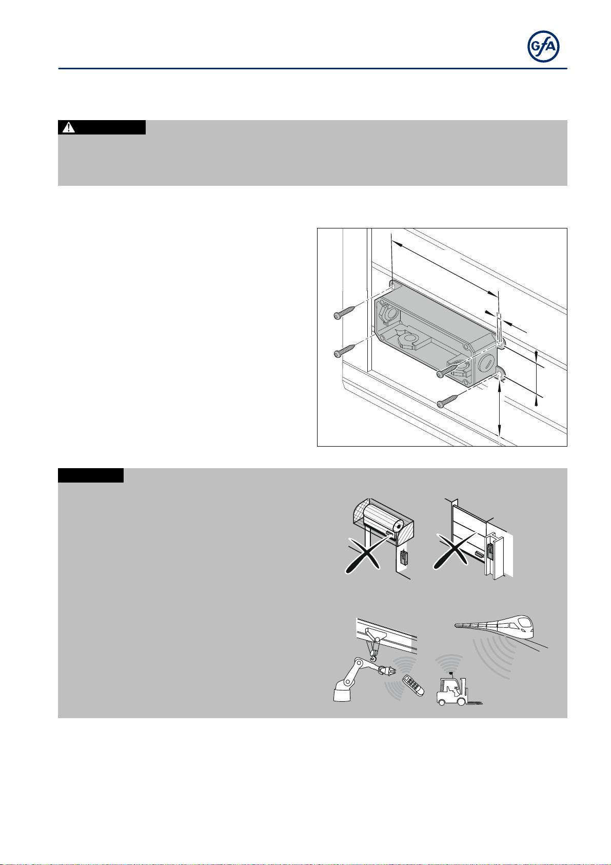
Installation on the door
Remove the cover from the door leaf box.
Screw the door leaf box onto the door
leaf.
145
5
40
min. 60
NOTIC
E
Observe the followin
g
notes for selectin
g
the
p
lace of installation:
Mount the WSD door-module as close to
the door control as possible.
The WSD door-module should not be
obscured by obstacles at stop and
during movement (holes in the ground,
crane runways, concrete or steel pillars,
shelves, etc.)
Radio systems may be affected by other
radio systems or EMC radiation. In case
of frequent interferences, changing the
channel may help. Should interferences
occur more frequently despite the
channel change, the system must be
replaced by a wired system.
4
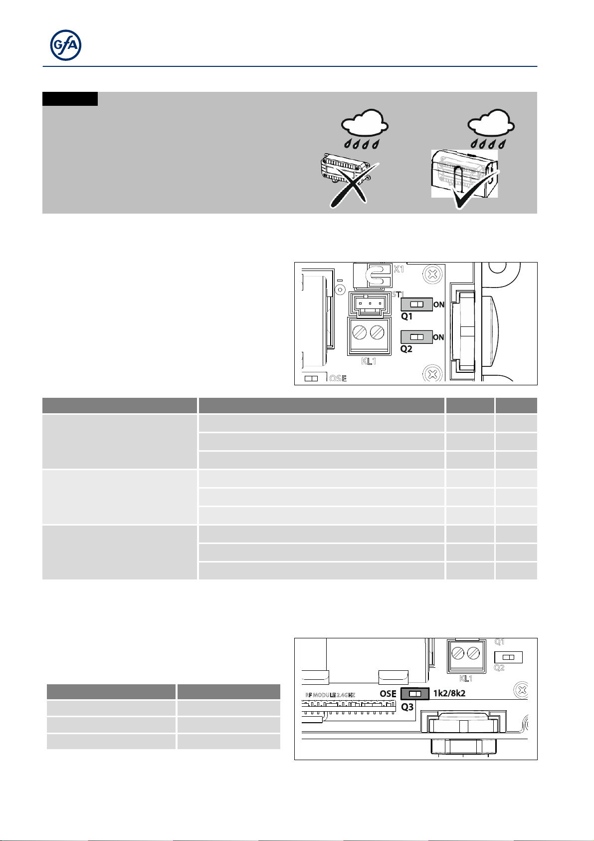
NOTIC
E
Damage due to moisture!
In humid areas, use the cover to protect the
door leaf boxes.
Covers are available as accessories:
Part no.: 40017478.00001
Set switches Q1 and Q2
You will find the switches Q1/Q2 on the board.
Q1/Q2 are used to switch the cross-fault
monitoring (see page 2 for definition) of the
slack-rope and pass-door switches.
Select the required setting from the following
table.
Slack-rope switch Pass-door switch Q1 Q2
2 switches with cross-fault
monitoring
One switch with cross-fault monitoring on on
One switch without cross-fault monitoring on off
Without switch on off
2 switches without cross-fault
monitoring
One switch with cross-fault monitoring off on
One switch without cross-fault monitoring off off
Without switch off off
Without switch One switch with cross-fault monitoring off on
One switch without cross-fault monitoring off off
Without switch off off
Table: Set Q1 and Q2
Set switch Q3
Use switch Q3 to select the type of safety edge.
Safety edge type Switch position
Optical left
Pneumatic right
Electrical right
5
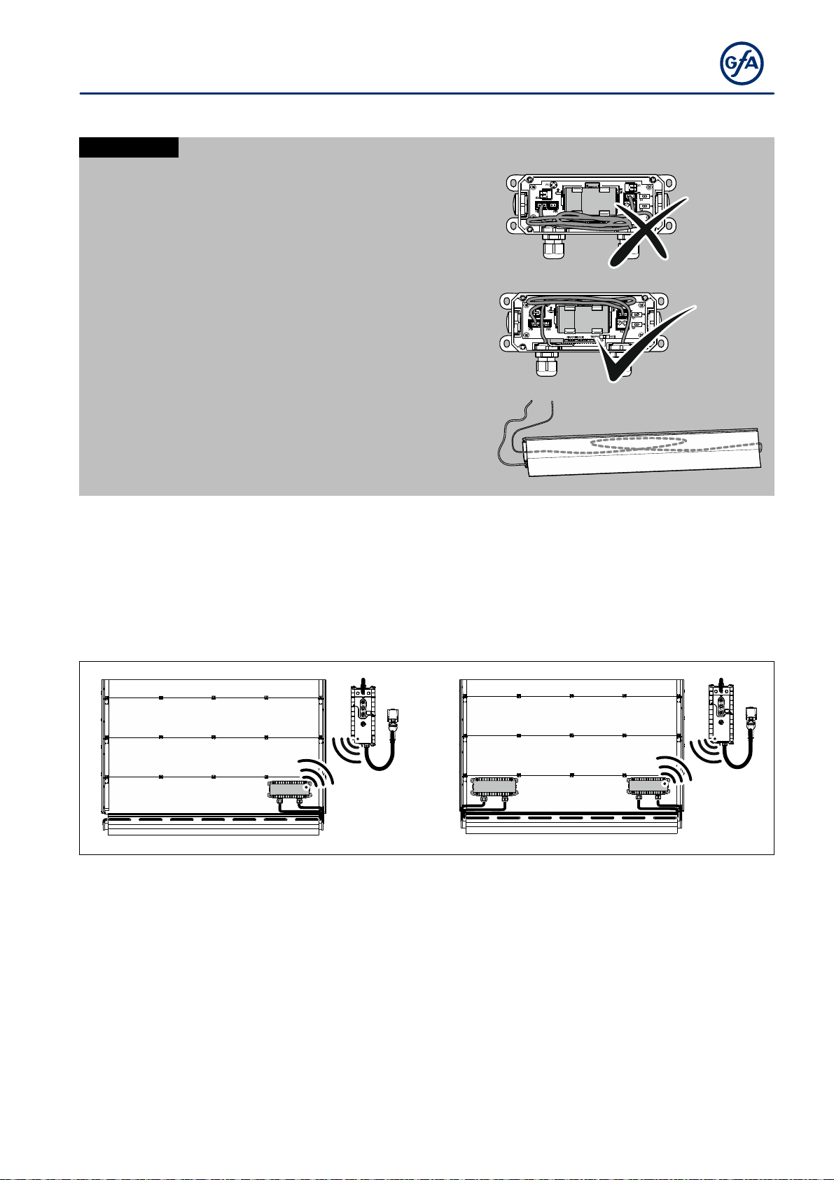
Laying the cables
NOTIC
E
Impairment of radio capacity!
Do not route the cables over the antenna. This
restricts the radio capacity and the battery
service life is reduced! ➊
Route excess cable over the battery.➋
Avoid excess cable length in the door leaf
boxes by laying a loop in the profile. ➌
➊
➋
➌
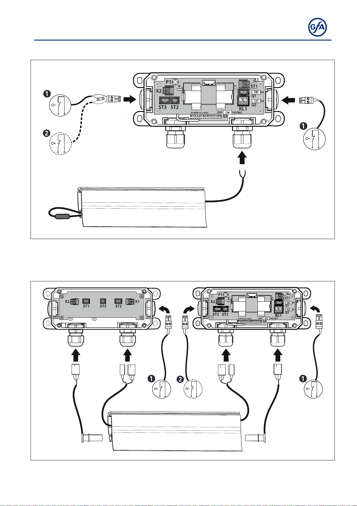
System overview
The available connection options are described below.
S
y
stem 1 S
y
stem 2
With one door leaf box. With 2 door leaf boxes, connected by one
cable.
6
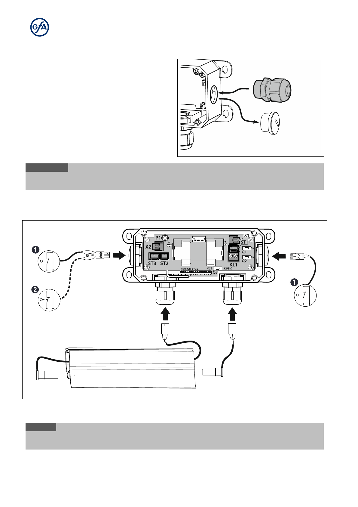
Insert cable glands
The WSD door-module is set up for connecting
two slack-rope switches and one pass-door
switch.
If you want to install a pass-door or slack-
rope switch, replace the side covers with
M16 x 1.5 cable glands.
M16 x 1,5
iNOT
E
Please note that only switches with performance level c (PLc) comply with the current
DIN EN 12453 standard.
Connection diagram System 1: OSE
ST3
ST1
2
1
X2 X1
2
1
2
1
➊ Slack-rope switch ➋ Pass-door switch
iNOT
E
Clamping range of the plug-in terminal for slack-rope and pass-door switches: 0.5 - 1.5mm².
Stripping length of the single conductors: 6.5 - 7mm, provided with wire end ferrules.
7
Connection diagram System 1: 1k2 and 8k2
2
1
X2
2
1
KL1
X1
2
1
➊ Slack-rope switch ➋ Pass-door switch
Connection diagram System 2: OSE
X1
2
1
ST3
ST2 ST1
ST3
ST2
ST1
2
1
2
1
X2 X1
➊ Slack-rope switch ➋ Pass-door switch
8
Finish installation
Fit the cover of the junction end box.
Switch on the voltage.
i
NOT
E
Damage due to moisture
Make sure that the screws and cable
g
lands are ti
g
htened.
Insert battery
The WSD door-module is powered by a battery. The battery life depends on the safety edge system
(optical, electrical), frequency of use and the size of the door, and is usually more than 1 year.
Replace the batteries during the annual maintenance of the door system.
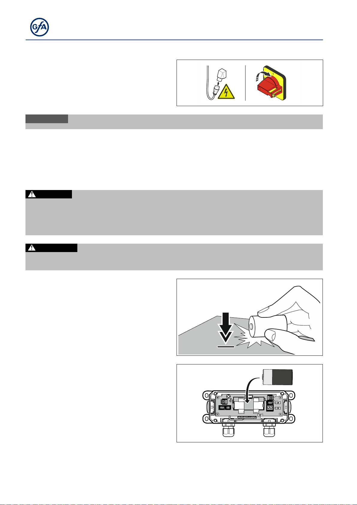
DANGER
Do not attempt to charge the battery.
Do not short-circuit the battery.
Do not disassemble or deform the battery.
Do not heat the battery. Store the battery in a cool and dry place.
CAUTION
Before inserting the battery, check the contact terminals of the WSD gate doo
r
-module.
Only insert the batteries if they are clean and dry and not deformed.
The battery must be depassivated before use.
Tap the battery about 6 times on a hard level
surface.
12
6x
Insert the battery.
LITHIUM
3.6V

9
Teach-in of WSD door-module
The following describes how to teach-in the WSD door-module on the door control. Also follow the
instructions for the door control. Assign a different radio channel to each door. Note the channels in
the door control housing to facilitate maintenance. Also observe the notes for selecting the channel on
the following pages.
3 sec
101
2
4
1x
3
4
39
1
40
4
1
40
2
2
105
1 s - 60 s
P1
1x
10
6
7
1x
3
10
8
The WSD door-module is now taught-in.
Check the function of the safety edge system.
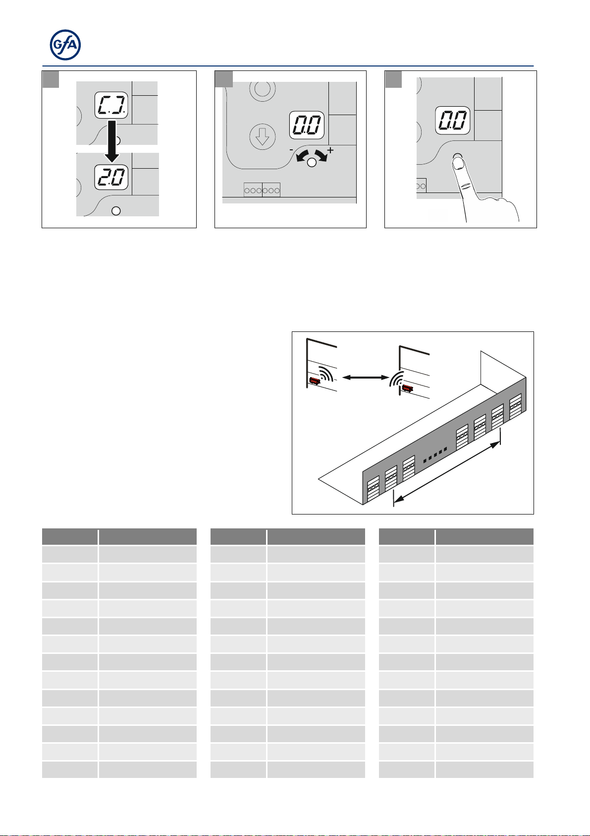
Selecting the channels
From door 40, channels are assigned in
duplicate. Duplicate radio channels must be
as far apart as possible. Plan in advance and
draw a hall plan.
Consequently, if the channels are set
incorrectly, the error 1.6 appears on the door
control.
TS 971 > SW 1.8 = 39 channels
TS 971 < SW 1.8 = 20 channels
Also note the following frequency table:
min. 75m
Ch5 Ch5
min.75m
Channel Frequency MHz Channel Frequency MHz Channel Frequency MHz
2 2400 28 2426 15 2452
22 2402 9 2428 35 2454
3 2404 29 2430 16 2456
23 2406 10 2432 36 2458
4 2408 30 2434 17 2460
24 2410 11 2436 37 2462
5 2412 31 2438 18 2464
25 2414 12 2440 38 2466
6 2416 32 2442 19 2468
26 2418 13 2444 39 2470
7 2420 33 2446 20 2472
27 2422 14 2448 40 2474
8 2424 34 2450 21 2476
Table: Frequency overview
Table of contents
Other GFA Control Unit manuals


Popular Control Unit manuals by other brands

Festo
Festo Compact Performance CP-FB6-E Brief description

Elo TouchSystems
Elo TouchSystems DMS-SA19P-EXTME Quick installation guide

JS Automation
JS Automation MPC3034A user manual

JAUDT
JAUDT SW GII 6406 Series Translation of the original operating instructions

Spektrum
Spektrum Air Module System manual

BOC Edwards
BOC Edwards Q Series instruction manual

KHADAS
KHADAS BT Magic quick start

Etherma
Etherma eNEXHO-IL Assembly and operating instructions

PMFoundations
PMFoundations Attenuverter Assembly guide

GEA
GEA VARIVENT Operating instruction

Walther Systemtechnik
Walther Systemtechnik VMS-05 Assembly instructions

Altronix
Altronix LINQ8PD Installation and programming manual


