GFA DC 8010 User manual
Installation instructions
Door Control Unit DC 8010
Part number: 30005854
USA - Version: d/02.2021

GfA ELEKTROMATEN GmbH & Co. KG
Wiesenstraße 81
40549 Düsseldorf
www.gfa-elektromaten.com
+49 211 / 500 90 0
US-Contact: 1-262-299-4740
Contact:
Failure to observe these installation instructions may
result in severe injury or death.
▪Read these instructions before using the product.
▪Include these instructions when passing on the product to
third parties.

1 Table of contents
1 Safety chapter ......................................................................1
1.1 Explanation of symbols .......................................................1
1.2 Target audience of the installation instructions ................... 1
1.3 Specieduse......................................................................2
1.4 General safety information ..................................................2
2 Storage and transport .........................................................3
3 Product overview .................................................................3
3.1 Technical data .....................................................................3
3.2 Overview of the DC 8010 ....................................................4
3.3 Overview of the control unit .................................................5
3.4 Status displays of the door control ......................................6
4 Mechanical installation .......................................................8
5 Electrical installation ...........................................................9
5.1 Fuses .................................................................................10
5.2 Connecting limit switch to the door control ........................ 10
5.3 Connecting motor to door control ...................................... 11
5.4 Motor cable conductor size (AWG) ................................... 13
5.5 Setting the operating voltage .............................................14
5.6 Connecting the door control to the power grid .................. 14
6 Connecting external devices ............................................15
X: Power supply 24V DC ...................................................16
X2: Safety edge
..................................................................16
X2: Door safety switch .......................................................19
X3: Emergency stop switch ...............................................19
X4: Switch for automatic closing ........................................20
X5: External control device ................................................21
X6: Photocell ......................................................................22
X7: Radio receiver / pull switch ..........................................23
X8: Switch for intermediate open ...................................... 24
X20/ X21: Potential-free relay contacts ............................. 24
X29: Separate control for magnetic brakes .......................25

7 Settingthenallimitpositions ...........................................26
8 Programming .........................................................................28
0.1 Operating mode ........................................................29
0.2 Output rotating direction ...........................................30
1.1/1.2Coarsecorrectionofnallimitposition .....................30
1.3-1.5Finecorrectionofnallimitpositions ........................31
1.6 Door positions for intermediate open .......................31
1.7/1.8 Switching position of relays X20/X21 ......................32
2.1 Safety edge in pre-limit area ....................................32
2.3 Automatic closing .....................................................33
2.4 Reaction of automatic closing to photocell ..............34
2.5 Limiting reversals .....................................................35
2.6 Radio and pull switch functions ...............................36
2.7/2.8 Relay functions of X20/X21 ....................................37
2.9 Specifying control device for intermediate open ......38
3.1 Force monitoring of sectional doors ........................39
3.2 Deactivation of the photocell ....................................40
3.8 Shorten/lengthen the reversing time ........................41
4.1-4.9 Frequency inverter functions ...................................42
8.5/8.6 Setting the maintenance cycle counter ....................44
9.1 Readout of cycle counter .........................................45
9.2 Readout of fault indications .....................................45
9.3 Readout of the cycle counter since last prog. change .....46
9.4 Readout of software version ....................................46
9.5 Reset to factory settings / use of GfA-Stick .............46
9 Maintenance and repair .........................................................47
9.1 Fault indication ......................................................................47
9.2 Maintenance ..........................................................................52
10 Disposal ..................................................................................52
1
1 Safety chapter
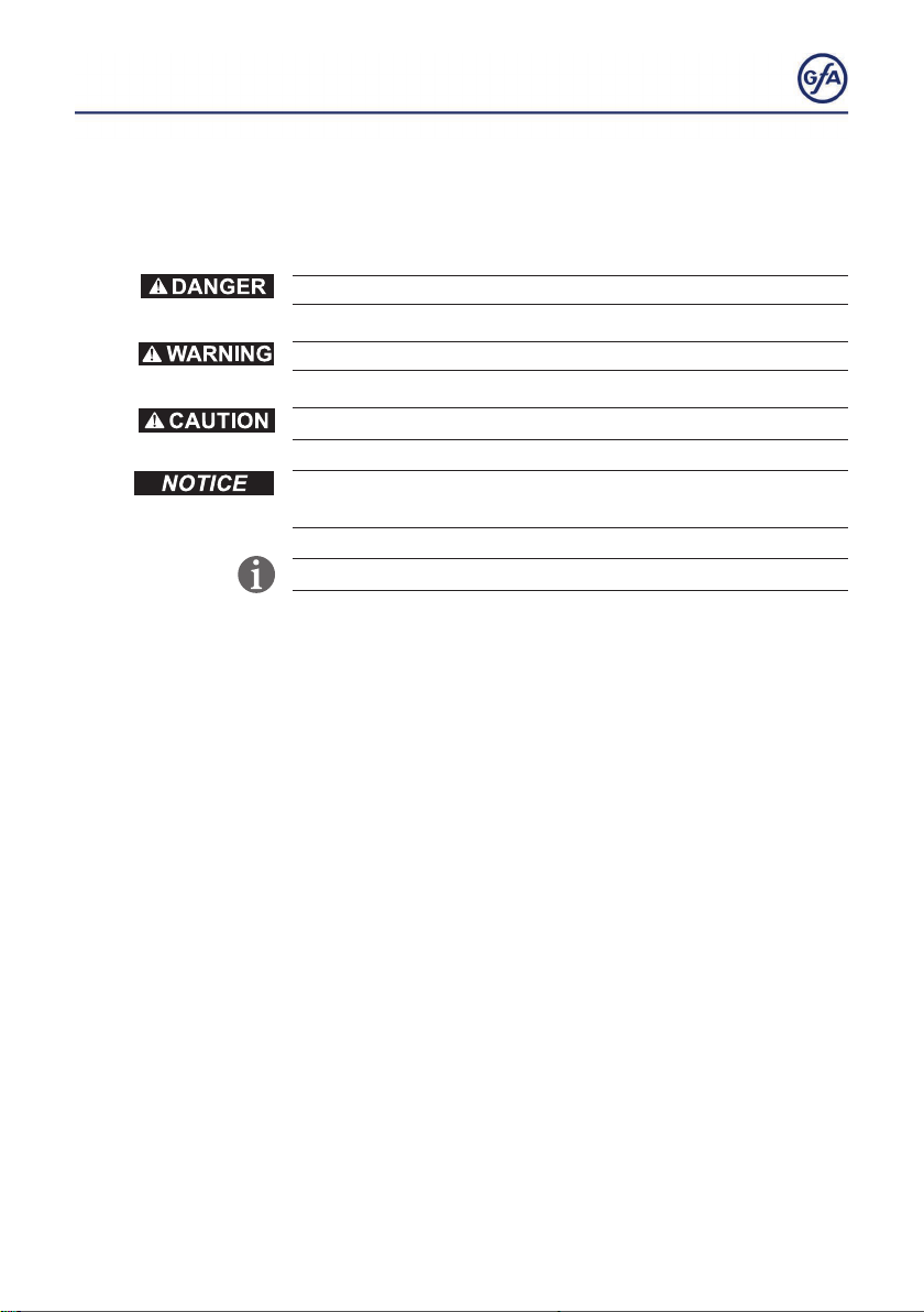
1.1 Explanation of symbols
Safety note: Non-compliance will result in death or severe injury.
Safety note: Non-compliance may result in death or severe injury.
Safety note: Non-compliance may result in injury.
Note: Non-compliance may result in property damage and
impairment of the product‘s functionality.
Note: Indicates useful other information.
1.2 Target audience of the installation instructions
These installation instructions are intended for trained
electricians and door installation technicians. They must be
capable of installing, commissioning and servicing the door
control.
Only trained electricians are allowed to execute the steps
described in chapter 5.
Trained electricians meet the following requirements:
▪They are familiar with the applicable safety and accident
prevention regulations.
▪They recognize hazards relating to electricity and the door
control and take safety precautions.
As user or operator, please contact the manufacturer of your
door product.
All work performed must be in accordance to NEC, local, state
and federal codes.
2
1.3 Specieduse
The door control is intended for installation in a force-actuated
door that is driven by a GfA ELEKTROMATEN (door drive unit)
with digital limit switch (DES). The control may be used only
indoors and exclusively for vertically moving doors.
Onlythespecieduseguaranteessafeoperation.
Modicationsareonlypermissiblewiththeconsentofthe
manufacturer.
1.4 General safety information
Danger to life due to electric shock!
Improper installation or repair may result in death or severe injury
from electrical current.
▪ Haveonlyqualiedelectricianscarryoutinstallation,
commissioning, and repairs.
▪Follow all safety instructions.
▪Operate the product only in perfect condition and carry out
regular maintenance.
▪Use only original spare parts.
Danger due to improper use of the product!
▪Do not allow children to operate the product unattended or
play with it.

3
2 Storage and transport
Store the door control in the original packaging in a dry place.
The temperature may be between 32 F (0 °C) and 122 F
(+50 °C).
The humidity must not exceed 93 %.
Do not stack anything on the door control. Transport the door
control in the original packaging. Avoid impacts, shocks, and
vibrations.
3 Product overview
3.1 Technical data
Property Specication
Dimensions of the control unit 340 mm x 235 mm x 125 mm
13.4“ x 9.3“ x 5“
Operating frequency 60 Hz
Adjustable operating voltages 220V / 460V / 575V
Max. output power for door drive unit 5.5 kW
External supply voltage
(internal electronic protection)
24V DC / 500mA
Inputs 24V DC / 10mA
Relay contacts 2
Load on relay contact,
resistive/inductive Ambient
24V 1A
Temperature during operation -10°C to +40°C /
14°F to 104°F
Humidity during operation max. 93%, non-condensing
Degree of housing protection IP65 / NEMA 4
Overvoltage Category II
Weight 3.5 kg

4
No. Description
1 4 Fuses
F1-F3: Motor fuses 20 A
F4: Control fuse 500mA
2 Motor connection
3 Ground
4 Power connection
5 Terminals X1: Operating voltage
6 Terminals X29: Relay for separate
brake control
7 Connector for GfA Bluetooth stick
8 Terminals X21: potential-free
form C relay (NO/NC)
9 Terminals X20: potential-free
form C relay (NO/NC)
10 Terminals X8: Intermediate open
No. Description
11 Terminals X7: Radio receiver, pull
switch
12 Terminals X6: Photocell
13 Terminals X: + (24V), - (GND)
14 Terminals X5: Control device
15 Terminals X4: Automatic closing
16 Terminals X3: Emergency STOP
17 Terminals X2: Safety edge
18 Selector switch
19 Connector for membrane push
button
20 Display
21 Terminals D: Digital limit switch
22 Terminals X0: Connector for
alternative keyboard
3.2 Overview of the control unit
5
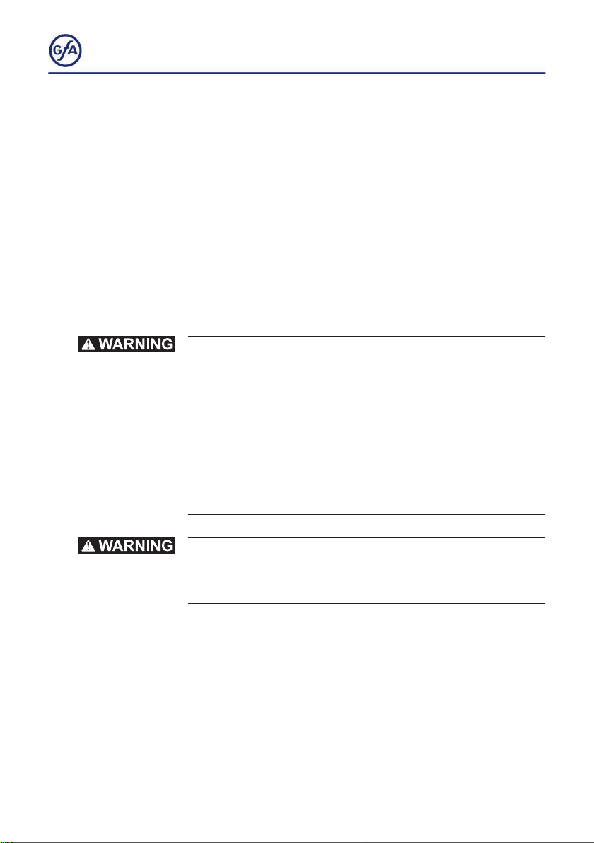
3.3 Status displays of the door control
Status displays
The following explains the symbols that the display of the door
control can represent.
▪The display of the door control consists of a double-digit
seven-segment-display.
▪The display can show symbols, letters, or numbers.
▪ Thegureshowsthedisplaywhenallsegmentsare
illuminated.
An E alternating with a number on the door control stands for a
movement command.
An Falternating with a number on the door control stands for a
fault indication. See Chapter 8.2.
Status display during initial operation
Thesesymbolsappearonlywhilethenallimitpositionsareset.
Display Description
Changing output rotating direction is active
SeeChapter6,settingnallimitpositions
Changing output rotating direction is completed
SeeChapter6,settingnallimitpositions
Flashing:TeachinginnallimitpositionOPEN
Flashing:TeachinginnallimitpositionCLOSE
6
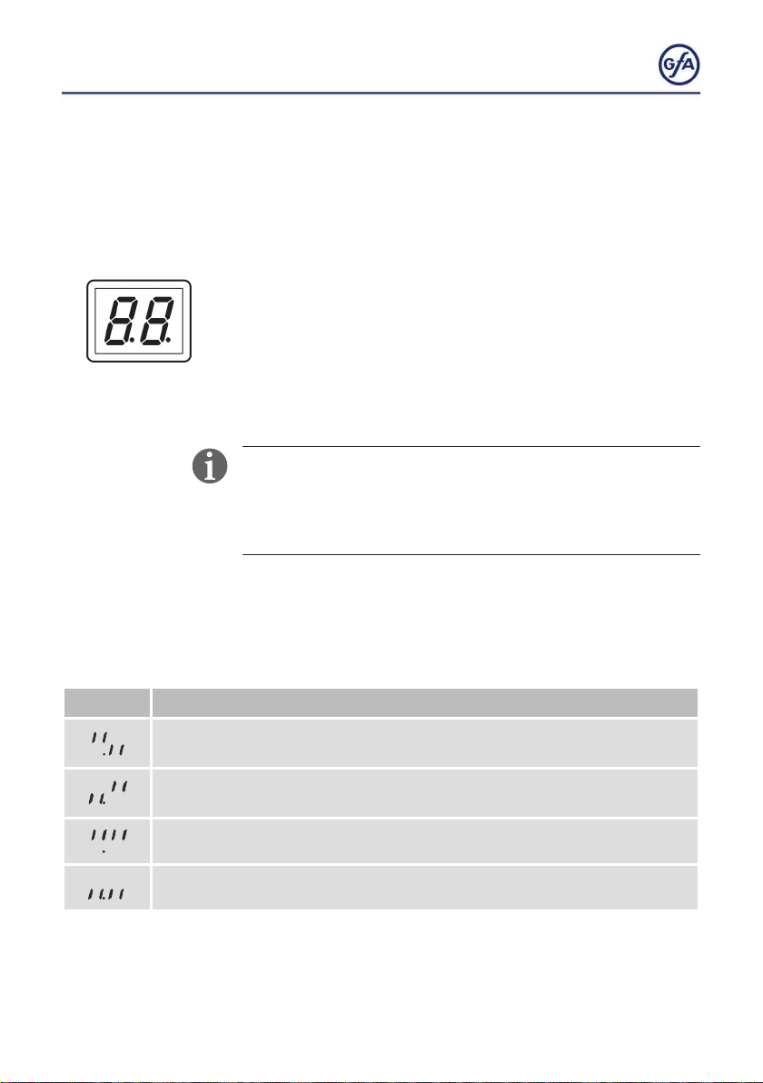
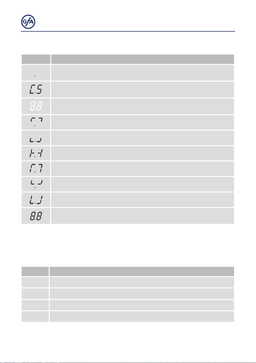
Status displays during operation
Display Description
Standby. A movement command or pressing a pushbutton exits the
standby mode.
Preset maintenance cycle counter has been reached.
See menu item 8.5/8.6.
Display does not light up. Indicates a short circuit or overload of the 24V
DC supply voltage.
Flashing: Door is opening.
Flashing: Door is closing.
Doorisstationarybetweentwonallimitpositions.
DoorisinnallimitpositionOPEN.
Door is in programmed intermediate open.
DoorisinnallimitpositionCLOSE.
Non-ashing:programmingdisabled.
Movement command display
The movement commands appear on the display when the
door control receives OPEN, CLOSE or STOP commands.
Display Description
E.
Display alternates between E. and number:
1. 1 OPEN command received.
1.2 STOP command received.
1.3 CLOSE command received.
This manual suits for next models
1
Table of contents
Other GFA Control Unit manuals


Popular Control Unit manuals by other brands

Festo
Festo Compact Performance CP-FB6-E Brief description

Elo TouchSystems
Elo TouchSystems DMS-SA19P-EXTME Quick installation guide

JS Automation
JS Automation MPC3034A user manual

JAUDT
JAUDT SW GII 6406 Series Translation of the original operating instructions

Spektrum
Spektrum Air Module System manual

BOC Edwards
BOC Edwards Q Series instruction manual

KHADAS
KHADAS BT Magic quick start

Etherma
Etherma eNEXHO-IL Assembly and operating instructions

PMFoundations
PMFoundations Attenuverter Assembly guide

GEA
GEA VARIVENT Operating instruction

Walther Systemtechnik
Walther Systemtechnik VMS-05 Assembly instructions

Altronix
Altronix LINQ8PD Installation and programming manual


