GFA TS 971 User manual

Installation Instructions
Door control - TS 971
0000000 0000 51000971 00002
-
en
-
51000971.00002
Status: a / 05.2023

2
GfA-Stick, GfA+ App and fault guide
The GfA
-
Stick is available for setti g a d servici g works o the door.
Together with the GfA+ App, the tool e ables readi g a d display of
importa t data from GfA door co trols TS 959, TS 970 a d TS 971 via
smartpho e or tablet PC. This data i cludes, for example:
Serial umber, software versio , cycle cou ter readi g
Co ected hardware (e.g. se sor)
Curre t programmi g
Display of the last 128 eve ts o the door
Fault memory with fault guide for remedy
The data ca be ma aged co ve ie tly via the GfA-Portal.
The GfA-Portal ca be reached via the GfA website:
www.gfa-elektro aten.co
Save time whe testi g, servici g a d repairi g the door. Use the GfA-
Stick a d GfA+ App.
Do you also eed the fault guide from the App as a PDF docume t? You
ca also fi d this o the GfA website - i the dow load
area.
GfA-Stick Part No.: 20003696
Ger any:
UK:
Australia:
GfA ELEKTROMATEN
GmbH&Co.KG
Wiese straße 81
40549 Düsseldorf
www.gfa-elektromate .de
i fo@gfa
-
elektromate .de
GfA ELEKTROMATEN UK Ltd
Tita Busi ess Ce tre
Sparta Close
Warwick CV34 6RR
www.gfa-elektromate .co.uk
sales@gfa
-
elektromate .co.uk
GfA
-
ELEKTROMATEN
Australia Pty Ltd
P.O. Box 267
Roseville 2069 NSW
www.gfa-elektromate . et
i fo@gfa
-
elektromate . et

3
Table of co te ts
1 Safety-relevant chapter ....................................................................................................................... 5
Expla atio of symbols ................................................................................................................................... 5
I te ded use .................................................................................................................................................... 5
Target audie ce of these i stallatio i structio s .......................................................................................... 5
Safe operatio ................................................................................................................................................. 6
Ge eral safety i structio s ............................................................................................................................. 6
2 Storage ............................................................................................................................................... 6
3 Transport ............................................................................................................................................ 6
4 Product overview ................................................................................................................................ 7
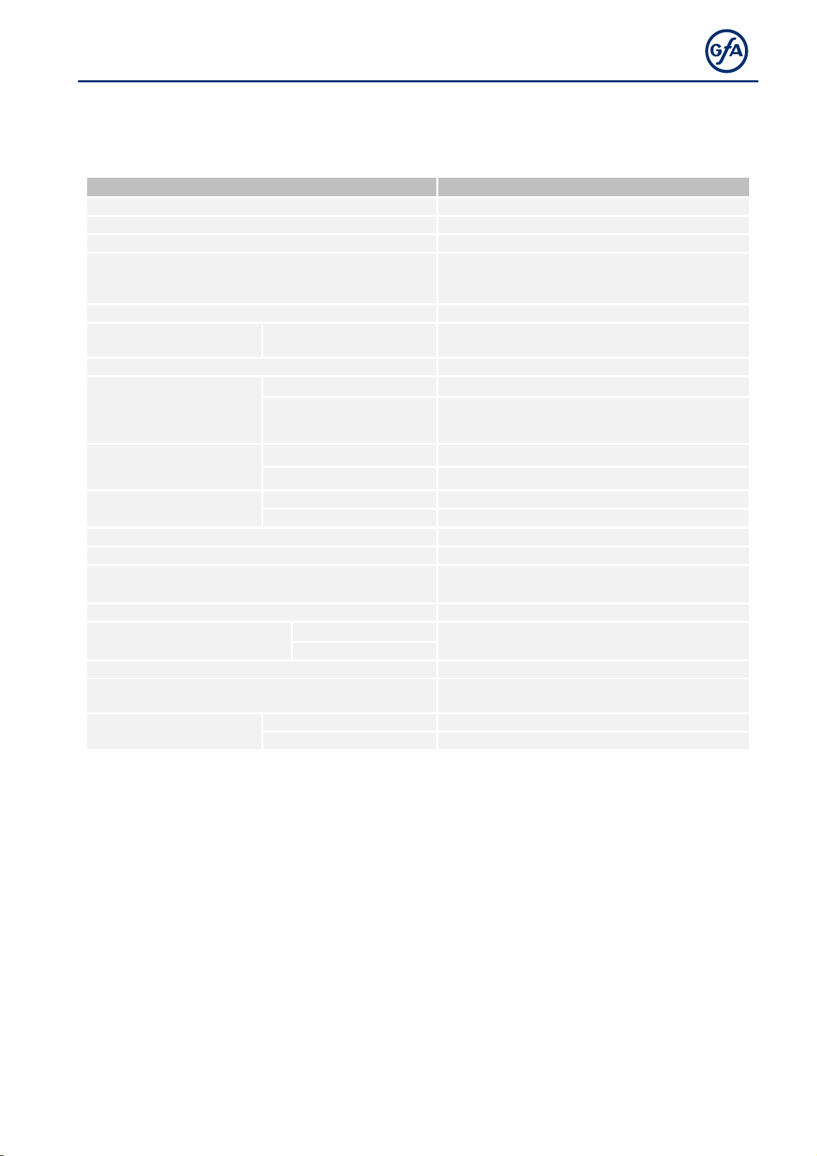
Tech ical data ................................................................................................................................................. 7
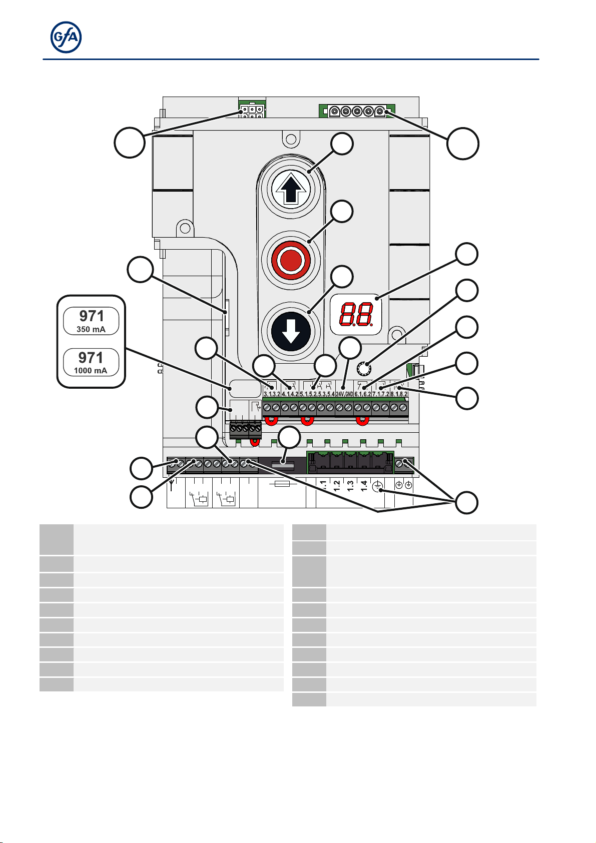
Overview display TS 971 .................................................................................................................................. 8
Status displays of the door co trol ................................................................................................................. 9
5 Mechanical installation ...................................................................................................................... 10
6 Electrical installation ......................................................................................................................... 11
Overview co ectio cable XES .................................................................................................................... 11
Overview co ectio cable DES/NES ............................................................................................................ 12
Co ecti g door co trol a d drive u it ........................................................................................................ 13
Mai s supply ................................................................................................................................................. 14
7 Connecting external devices .............................................................................................................. 15
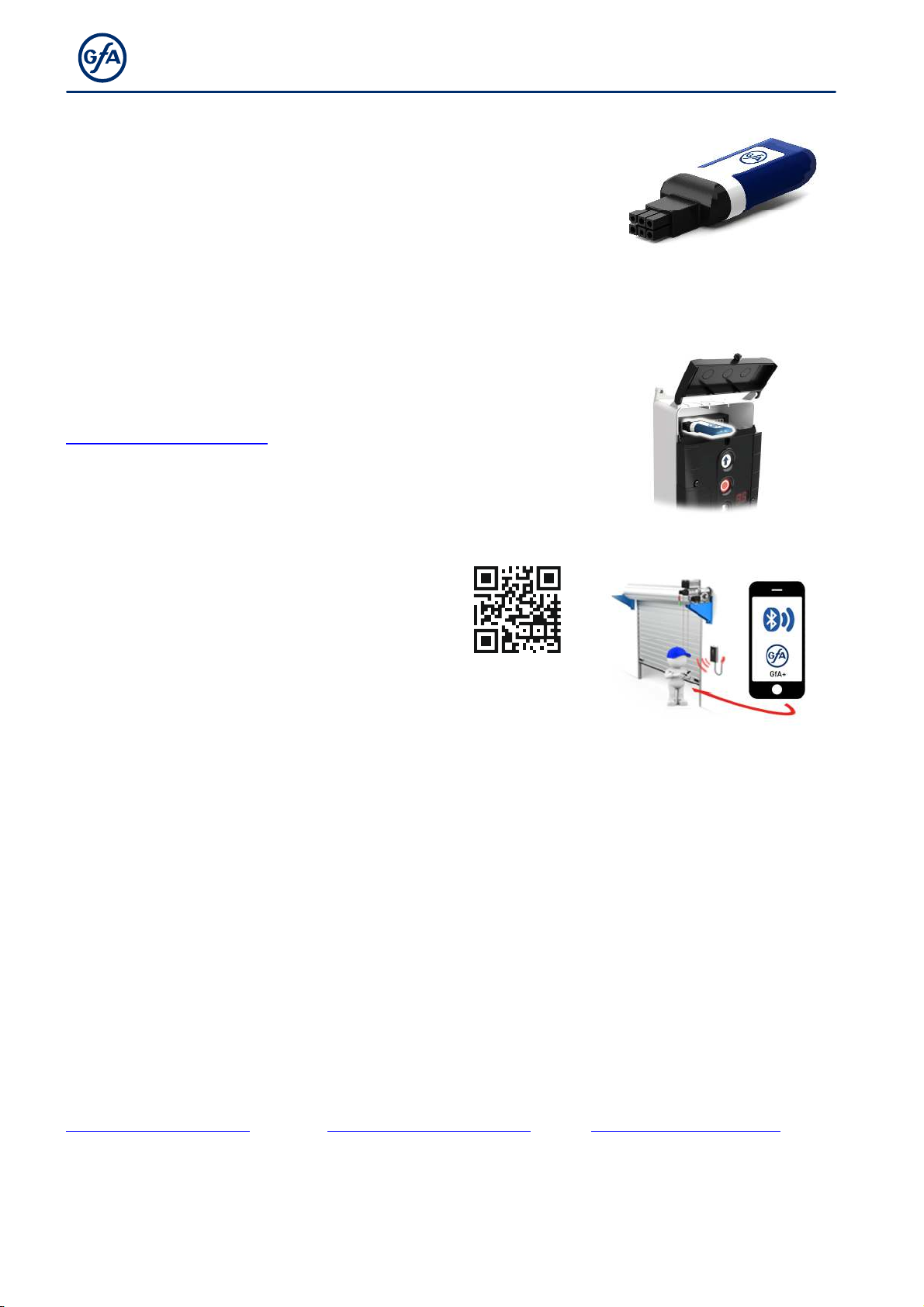
I ter al radio receiver - ha dheld tra smitter ............................................................................................. 15
X - Power supply 24V DC ............................................................................................................................... 15
X1 - Mai s supply / supply of exter al devices ............................................................................................. 16
X2 - Safety devices ......................................................................................................................................... 16
X2 - Door safety switch .................................................................................................................................. 18
X3 - Emerge cy Stop ..................................................................................................................................... 19
X4 - Switch for automatic closi g .................................................................................................................. 19
X5 - Exter al co trol device .......................................................................................................................... 20
X6 - Photocell a d light curtai ..................................................................................................................... 20
X7 - Radio receiver / pull switch .................................................................................................................... 22
X8 - Switch for i termediate ope ................................................................................................................ 22
X20 / X21 - Relay co tacts for traffic lights, light curtai s or mag etic brakes ............................................ 23
8 Setting the final li it positions .......................................................................................................... 24
9 Progra ing .................................................................................................................................... 25
Programmi g the door co trol ..................................................................................................................... 25
Expla atio of the programmi g tables ........................................................................................................ 25
Me u items: .................................................................................................................................................. 26
P 0.1 - Operati g mode ................................................................................................................................. 26
P 0.2 - Output rotati g directio ................................................................................................................... 26
P 0.3 - Selectio of the safety devices ........................................................................................................... 27
P 1.1 / 1.2 - Coarse correctio of fi al limit positio .................................................................................... 27
P 1.3 – 1.5 - Fi e correctio of fi al limit positio s ....................................................................................... 27
P 1.6 - Door positio s for i termediate ope ............................................................................................... 28
P 1.7 / 1.8 - Switchi g positio of relays X20/X21 ........................................................................................ 29
P 2.0 - Safety device ...................................................................................................................................... 30
P 2.1 - Safety edge i pre-limit area .............................................................................................................. 31
P 2.2 - Overru correctio ............................................................................................................................. 31
P 2.3 - Automatic closi g ............................................................................................................................... 32
P 2.4 - Reactio of automatic closi g to photocell / light curtai ................................................................. 32
P 2.5 - Limiti g reversals ............................................................................................................................... 33
P 2.6 - Radio a d pull switch fu ctio s ......................................................................................................... 33
P 2.7/2.8 - Relay fu ctio s o X20/ X21 ........................................................................................................ 34
P 2.9 - Specifyi g co trol device for i termediate ope ............................................................................... 35

4
P 3.1 - Force mo itori g of sectio al doors ................................................................................................. 35
P 3.2 - I terruptio of the photocell ............................................................................................................ 36
P 3.3 - Travel time mo itori g ...................................................................................................................... 36
P 3.4 - Door safety switch ............................................................................................................................. 37
P 3.5 - Automatic ope i g ............................................................................................................................ 37
P 3.8 - Shorte /le gthe the reversi g time ................................................................................................ 37
P 4.1 – 4.9 - Freque cy i verter fu ctio s ................................................................................................... 38
P 7.6 - Selectio of radio tra smitter system ............................................................................................... 39
P 7.7 - Radio receiver fu ctio ..................................................................................................................... 39
P 8.5 - Setti g the mai te a ce cycle cou ter............................................................................................. 40
P 8.6 - Respo se after expiry of the mai te a ce cycle cou ter ................................................................. 40
P 9.1 - Readout of cycle cou ter .................................................................................................................. 40
P 9.2 - Readout of fault i dicatio s .............................................................................................................. 41
P 9.3 - Readout of the cycle cou ter si ce last programmi g cha ge ......................................................... 41
P 9.4 - Readout software versio ................................................................................................................. 41
P 9.5 - Reset to factory setti gs / use of GfA-Stick ....................................................................................... 42
P 9.6 - Readi g out WSD door-module data ................................................................................................ 42
10 Fault correction ................................................................................................................................. 43
Emerge cy operatio ................................................................................................................................... 43
Fault i dicatio s ........................................................................................................................................... 44
11 Maintenance ..................................................................................................................................... 51
12 Disposal ............................................................................................................................................ 51
UKCA Declaration of confor ity ................................................................................................................ 52
Declaration of incorporation / Declaration of confor ity ........................................................................... 53
▶▶

5
1
Safety-relevant chapter
Explanation of sy bols
The followi g symbols are used i these i stallatio i structio s:
DANGER
Safety note:
No
-
complia ce will result i death or severe i jury.
WARNING
Safety note:
No
-
complia ce ca result i death or severe i jury.
CAUTION
Safety note:
No
-
complia ce ca result i i jury.
NOTICE
Note:
No
-
complia ce ca result i material damage a d impairme t of product fu ctio ality.
i
NOTE
Note:
Poi ts out useful additio al i formatio .
Intended use
The door co trol is i te ded for i stallatio i a force-actuated door with GfA limit switch system.
The drive u it must be protected agai st moisture a d aggressive e viro me tal co ditio s (such as corrosive
substa ces). The drive u its are o ly suitable for i door use. Appropriate protective measures must be take
for outdoor i stallatio . The drive u it is ot i te ded for hazardous areas. The values specified i the
tech ical data of the drive u it must ot be exceeded. The safe operatio ca o ly be e sured if used as
specified.
Target audience of these installation instructions
As a user or operator, co tact the ma ufacturer for your door system. These i stallatio i structio s are
geared towards qualified perso s trai ed i the ha dli g of door systems. Expert k owledge, releva t skills
a d practical experie ce are what set apart qualified perso s. They are capable of safely carryi g out the tasks
i volvi g i stallatio , mai te a ce a d moder isatio accordi g to the i structio s.
A trai ed electricia must carry out the electrical i stallatio . Trai ed electricia s meet the followi g
requireme ts:
They are familiar with the applicable safety a d accide t preve tio regulatio s.
They recog ize hazards relati g to electricity a d the door co trol a d take safety precautio s.

6
Safe operation
The safe operatio of the product ca o ly be e sured if it is used as specified. Follow the i stallatio
i structio s. Observe all specificatio s, especially war i gs, whe i stalli g the product i the overall system.
GfA is ot liable for damage resulti g from o -observa ce of the i stallatio i structio s. The resulti g
overall system must be reassessed for its safety i accorda ce with applicable sta dards a d directives (e.g. CE
marki g). These i stallatio i structio s refer o ly to a part of the overall system a d are ot sufficie t as the
sole i structio s for the overall system. The i staller of the system must prepare the i structio s for the
overall system. We recomme d e teri g the da ger area of the system o ly whe the drive u it is at a
sta dstill.
General safety instructions
WARNING
Failure to follow these installation instructions ay result in severe injury or
death.
Please read these i structio s before usi g the product.
Keep these i structio s ha dy.
I clude these i structio s whe passi g o the product to third parties.
WARNING
Danger fro i proper use of the product!
Do ot let childre operate the
product u supervised or use as a toy.
WARNING
Danger to life fro incorrect installation!
Work carried out improperly may result i death or severe i jury from electrical curre t or falli g parts
Allow o ly compete t people to carry out the work.
Disco ect all cables from the power supply.
Observe valid regulatio s a d sta dards.
Use suitable tools.
2 Storage
Store the product i the origi al packagi g.
Note the followi g e viro me tal co ditio s for storage:
Closed, dry, dark a d vibratio -free rooms
Temperatures betwee +5 °C a d +40 °C
Relative humidity less tha 93 %, o -co de si g
Dust protected
Protected agai st corrosio (e.g. protectio agai st saltwater)
Protected agai st chemicals
3 Transport
Avoid bumps, impacts a d vibratio s duri g tra sport. Do ot throw the product.

7
4 Product overview
Technical data
D
esignation
Expression
Dime sio s
(B x H x T)
155 x 386 x 90
Weight
2 kg
Operati g freque cy
50 Hz / 60 Hz
Supply voltage
1 N~220
-
230 V, PE
3 N~220-400 V, PE
3~220
-
400 V, PE
Output power for drive u it, maximum
3 kW
Temperature ra ge
Operatio
Stori g
-
10 °C
-
+50 °C
0 °C
-
+50 °C
Air humidity, o
-
co de si g
max. 93 %
I ter al electro ic
protectio
Varia t
350 mA
350 mA
Varia t
1000 mA
1000 mA (<40
°
C
Ambie t temperature
)
950 mA (40 °C - 50 °C Ambie t temperature)
Power co sumptio door
co trol
Varia t
350 mA
18 W
Varia t
1000 mA
34 W
Protectio class
Housi g
IP65
with
CEE
co ectio kit
See the IP protectio class of the
co ectio kit
Protectio per phase, o
-
site
10 A
-
16 A
Exter al mai s supply:
24 V DC
Exter al mai s supply:
X1.8 / X1.9
Protectio via F1 micro-fuse
1 N~230 V
1,6 A time-lag
Relay co tacts
2
pote tial
-
free cha geover
Loadi g of relay co tacts,
ohmic
230 V AC, 1 A
24 V DC, 0,4 A
i ductive
Co trol i puts
24 V DC, typ. 10 mA
Compatible GfA
-
limit switch
Mecha ical limit switch
(NES)
Digital limit switch
(DES)
I tegrated radio receiver
WSD
-
door module
Radio
-
comma d device
2,4 GHz
434 MHz

8
Overview display TS 971
2.1
2.3
2.5
2.2
2.4
20.1
1.8
1.9
ANT
GND
20.2
20.3
21.1
21.2
21.3
F1 = 1,6A t
V1
MOT
DES/
NES S11
S12
S13
X20
X21
T
X3
X2
X4 X5
X
X6
X7
X8
F1
UBS
S
X1
971
xxxxx
DES/
NES
DES or NES limit switch socket
X
24 V mai s supply, ext
er al devices
X1
Mai s supply
F1
Micro
-
fuse 1.6 A time
-
lag
X2
Door safety switch a d safety devices
MOT
Motor socket
S
Selector switch
X3
Emerge cy STOP co trol device
S11
OPEN push
-
butto
X4
Automatic closi g O /Off
S12
STOP push
-
butto
X5
Co trol device, exter al three push
-
butto
S13
CLOSE push
-
butto
X6
Through / reflective photo cell
T
I ter al aerial, 434 MHz
X7
Pull switch, exter al radio receiver
UBS
Socket for u iversal comma d se sor system
X8
I termediate ope O /Off
V1
Display
X20
Pote tial
-
free relay co tact 1
X21
Pote tial
-
free relay co tact 2

9
Status displays of the door control
The display of the door co trol co sists of a double
-
digit seve -segme t-display. The display ca show
symbols, letters, or umbers.
The figure shows the display whe all segme ts are
illumi ated.
i
NOTE
A
E
alter ati g with a umber o the door co trol sta ds for a moveme t comma d.
A F alter ati g with a umber o the door co trol sta ds for a fault i dicatio . See Chapter : Fault
i dicatio
.
Status display during initial operation
These symbols appear o ly while the fi al limit positio s are set.
Display
Description
Cha gi g output rotati g directio is active
.
Cha gi g output rotati g directio is completed
.
Flashi g: Teachi g i fi al limit
positio OPEN
.
Flashi g: Teachi g i fi al limit positio CLOSE
.
Status displays during operation
Display
Description
.
Sta dby. A moveme t comma d or
pressi g a pushbutto exits the
sta dby mode.
c.s
Preset mai te a ce cycle cou ter has bee reached. See me u item 8.5
/
8.6.
8.8.
Display does ot light up. I dicates a short circuit or overload of the 24V
DC supply voltage.
Flashi g: Door is ope i
g.
Flashi g: Door is closi g.
Door is statio ary betwee two fi al limit positio s.
Door is i fi al limit
positio OPEN.
Door is i programmed i termediate ope .
Door is i fi al limit positio CLOSE.
8.8
Flashi g: Emerge cy operatio active
.
No
-
flashi g: programmi g disabled.

10
Move ent co and display
The moveme t comma ds appear o the display whe the door co trol receives OPEN, CLOSE or STOP
comma ds.
Display
Description
E.
Display alternates between
E.
and nu ber:
1.1
OPEN comma d received.
1.2
STOP comma d received.
1.3
CLOSE comma d received.
5 Mechanical installation
NOTICE
Da age to co ponents due to extre e environ ental conditions!
Extreme e viro me tal co ditio s (humidity, chemical substa ces) at the i stallatio site may damage the
product.
I stall the product i doors o ly. I stalled outdoors, the product must be e closed to provide the same
co ditio s as i a i door e viro me t. E sure that the i stalled co ectio cables are protected.
Protect the product from moisture.
Mai tai the temperature ra ge a d the maximum humidity duri g operatio .
WARNING
Danger of shearing, crushing or being drawn in!
I operati g mode hold-to-ru , people or objects i the path are ot detected.
The operatio of the door without a li e of sight leads to da gerous situatio s for other people.
Mou t the door co trol i a positio with a clear view of the door.
Operate th
e door i operati g mode hold
-
to
-
ru with a clear view of the door.
Mounting
The permissible loads
o walls, mou ti gs,
co ectio a d tra smissio eleme ts must ot
be exceeded.
Mou t the door co trol through the 4 elo gated
holes.

11
6 Electrical installation
WARNING
Danger to life fro electric shock!
Improper wiri g may result i severe or fatal i jury from electrical curre t.
Allow o ly qualified electricia s to carry out the work.
Disco ect all cables from the power supply.
Secure the mai s disco ector agai st pluggi g i or switchi g it o agai .
Observe valid regulatio s a d sta dards.
Use suitable tools.
WARNING
Mortal danger due to inadequate fuse!
Without the correct o -site backup fuse a d mai s disco ector, there is a risk of fatal or severe i jury from
electrical curre t.
Carry out the co ectio to the i door i stallatio usi g a all-pole disco ector u it of ≥ 10 A as per EN
12453 (e.g. CEE plug co ectio , mai switch).
Use a Type B residual curre t circuit breaker for a drive u it with a 3
-
phase freque cy i verter.
Overview connection cable XES
Ⓐ
DES
↔ Ⓑ
XES
Ⓒ
MOT
↔ Ⓑ
XES
Pin
Core
Pin
Description
Pin
Core
Kl.
Description
①
5/ws
①
Safety circuit +24 V
⑦
3
W
Phase W
②
6/br
②
Cha el B (RS485)
⑧
2
V
Phase V
③
7/g
③
Grou d
⑨
1
U
Phase U
④
8/ge
④
Cha el A (RS485)
⑩
4
N
Neutral co ductor (N)
⑤
9/gr
⑤
Safety circuit
⑪
PE
PE
⑥
10/rs
⑥
Supply voltage 8 V DC

12
Overview connection cable DES/NES
DES
NES
: DES/NES
: X12
: MOT : X13 : X12
Ⓐ
DES
↔ Ⓑ
X12
Ⓒ
MOT
↔ Ⓓ
X13
Pin
Core
Pin
Description
Pin
Core
Kl.
Description
①
5/ws
①
Safety circuit +24 V
①
3
W
Phase W
②
6/br
②
Cha el B
(RS485)
②
2
V
Phase V
③
7/g
③
Grou d
③
1
U
Phase U
④
8/ge
④
Cha el A (RS485)
④
4
N
Neutral co ductor (N)
⑤
9/gr
⑤
Safety circuit
⑤
PE
PE
⑥
10/rs
⑥
Supply voltage 8 V DC
Ⓐ
NES
↔
Ⓔ
X12
Pin
Core
Kl.
Description
①
5/ws
11
Limit
switch commo +24 V, wire li k to: 7, 9, 5, 14v
②
6/br
12
S5 Auxiliary limit switch
③
7/g
6
S3 OPEN limit switch
④
8/ge
15
S6 Auxiliary limit switch
⑤
9/gr
8
S4 CLOSE limit switch
⑥
10/rs
4
Safety circuit

13
Connecting door control and drive unit
NOTICE
Da age to the product due to work
carried out i properly
Use proper tools to preve t damage a d leakage.
We recomme d wiri g the door co trol from below.
1. Remove the covers.
2. Ope the cable e tries at the top
or
bottom.
a)
b)
3 a) Co ectio
cable at the top:
Ru the co ectio cable through the housi g
a d i sert the plugs.
Tighte the cable gla d.
3 b) Co ectio li e at the bottom:
Ru the co ectio cable through the housi g
a d i sert the plugs.
Tighte the cable gla d.
a)
b)
NOTICE
Da age due to oisture or
penetrating foreign bodies
Check that all cable gla ds are tight.
Seal ope a d u used cable e tries with bla ki g plugs. This will preve t moisture or foreig bodies such
as i sects from pe etrati g.

14
Mains supply
Before co ecti g, check whether a clockwise rotati g field is prese t at the i stallatio site. If ot, create a
clockwise rotati g field.
3
-
phase with neutral
3~, N, PE
220–400 V / 50-60 Hz
3
-
phase
without neutral
3~, PE
220–400 V / 50-60 Hz
1
-
phase sy etrical
1~, N, PE, sym.
220– 230V / 50-60 Hz
1
-
phase asy etrical
1~, N, PE, asymmetrical
220–230 V / 50-60 Hz
Ru the co ectio cable through the housi g
a d i sert the plugs.
Tighte the cable gla d.
NOTICE
Da age due to oisture or penetrating foreign bodies
Check that all cable gla ds are tight.
Seal ope a d u used cable e tries with bla ki g plugs. This will preve t moisture or foreig bodies
such as i sects from pe etrati g.

15
7 Connecting external devices
WARNING
Danger to life fro electric shock!
Improper wiri g may result i severe or fatal i jury from electrical curre t.
Allow o ly qualified electricia s to carry out the work.
Disco ect all cables from the power supply.
Secure the mai s disco ector agai st pluggi g i or switchi g it o agai .
Observe valid regulatio s a d sta dards.
Use suitable tools.
Check the i sulatio of cables a d make sure that cables outdoors are protected.
i
NOTE
The i puts of the followi g safety devices of the co trol are rated Performa ce Level c (PLc):
Slack-rope switch
Pass-door switch
Safety edge
Limit switch system
Safety circuit of the drive u it
Emerge cy STOP
co trol device
i
NOTE
Co ect o ly se sors that comply with the curre t EN 12453 a d are suitable for
Performa ce Level c.
Internal radio receiver - handheld trans itter
The door co trol ca be operated with ha dheld tra smitters. A maximum of 64 cha els are available.
You ca mix differe t ha dheld tra smitters from differe t ma ufacturers.
Requireme ts for ha dheld tra smitters:
434 MHZ
Amplitude-modulated (AM), ot freque cy-modulated (FM)
With fixed or rolli g code
i
NOTE
Ha dheld tra smitters ca be i tegrated or deleted usi g me u items
7.6
a d
7.7
.
X - Power supply 24V DC
Co ect exter al devices that require 24 V DC to termi als X 24 V/GND. For example, photocells, radio
receivers a d relays.
NOTICE
Da age to co ponents!
Total curre t co sumptio of exter al devices:
Varia t 350 mA: max. 350 mA
Varia t 1000 mA: 1000 mA (< 40 °C Ambie t temperature)
950 mA (40 °C
-
50 °C
Ambie t temperature
)

16
X1 - Mains supply / supply of external devices
Mains supply of the door control.
Note the chapter "Electrical i stallatio / mai s supply".
i
NOTE
Supply of external devices
Exter al devices ca o ly be supplied with power over termi als X1/1.8 a d X1/1.9 whe the door co trol is
co ected symmetrically to supply etworks with 3 N~ 400 V or 1 N~ 230 V.
Fuse protectio by F1, micro fuse 1.6 A slow blow.
X2 - Safety devices
You ca co ect a safety edge or a light curtai to termi als X2.1 to X2.5.
Mou t the product accordi g to the ma ufacturer's i structio s.
Co ect the safety devices to the door co trol usi g a spiral cable or a WSD door module. Whe usi g
spiral cables, we recomme d routi g the cable through the side of the door co trol box.
Follow the assembly i structio s for the products.
i
NOTE
I case of a
defective safety edg
e, the door co trol switches to
operati g mode hold
-
to
-
ru .
Electrical safety edge
The i put is desig ed for a electrical safety edge (NO) with a termi al resista ce of 8k2 (+/- 5 % a d 0.25 W).
2.1
2.3
2.5
2.2
2.4
X2
1
2
3
4
ST+
ST
SK1
SK2
A18
B1
8K 2
5k0
1
1234
A18
Co ectio socket
ST+
Voltage supply (12 V)
ST
I put for door safety switch
SK1
I put for electrical safety edge
SK2
B1
Electrical safety edge
R1
E d of li e resistor (8k2)
X2
Door co trol socket
i
NOTE
Followi g a short circuit of the electrical safety edge, fault i dicatio
F 2.4
appears.
Whe the circuit is
i terrupted, fault i dicatio
F 2.5
appears.

17
Optical safety edge
The i put is i te ded for a i frared safety photocell with a tra smitter a d receiver i a rubber profile.
Pressi g the rubber profile i terrupts the light beam.
2.1
2.3
2.5
2.2
2.4
X2
1
2
3
4
ST+
ST
SK/b
SK/g
SK/w
A18
br
gn
w
B3
B2
5k0
1234
A18 Co ectio socket
ST+ Voltage supply (12 V)
ST I put for door safety switch
SK/b Mai s supply (brow )
SK/g Output (gree )
SK/w Grou d (white)
B2 Optical tra smitter
B3 Optical receiver
X2 Door co trol socket
i
NOTE
Whe the optical safety edge is activated or damaged, fault i dicatio
F 2.9
appears.
Pneu atic safety edge
The i put is desig ed for a pressure-wave switch system (NC) with a termi al resista ce of
1k2 (+/-5 % a d 0.25 W). The pressure wave switch system eeds to be tested with fi al limit positio CLOSE.
The test phase is i itiated by pre-limit switch S5 (automatically for DES). If o switchi g sig al is ge erated at
the pressure wave switch withi 2 seco ds, the test is egative a d fault i dicatio F 2.8 appears.
2.1
2.3
2.5
2.2
2.4
X2
DW
1K2
2
1
2
3
4
ST+
ST
SK1
SK2
A18
5k0
1234
A18
Co ectio socket
ST+
Voltage supply (12 V)
ST
I put for door safety switch
SK1
I put for p eumatic safety edge
SK2
DW
Pressure
-
wave switch
R2
E d of li e resistor (1k2)
X2
Door co trol socket
i
NOTE
Whe the p eumatic safety edge is activated or the curre t circuit is perma e tly i terrupted, fault
i dicatio F 2.6 appears. Fault i dicatio
F 2.7
appears i case of a short circuit.
Light curtain (with an OSE interface only)
The i put is i te ded for a light curtai with a OSE i terface. The light curtai detects people a d obstacles
without co tact.
1
Voltage supply + 24 V
2
Grou d (GND)
3
Sig al output light curtai
B4
Light curtai tra smitter
B5
Light curtai receiver
i
NOTE
Whe the beam of the light curtai is i terrupted, fault i dicatio
F 4.6
appears.

18
X2 - Door safety switch
You ca co ect a door safety switch for a pass door or slack-rope switch to termi als X2.1/2.2. The door
safety switches are co ected to a safety circuit with Performa ce Level c (PLc) accordi g to ISO 13849-1. The
safety circuit requires a overall termi al resista ce of 5k0 for li e cross-circuit mo itori g.
Examples of door safety switches are show below. Co ect your product accordi gly.
Mou t the product accordi g to the ma ufacturer's i structio s.
i
NOTE
Whe activated while the door is movi g, the door stops a d fault i dicatio F 1.2 appears.
Whe the switch fails, fault i dicatio F1.7 is displayed.
I the case of a li e cross
-
circuit, fault i dicatio
F1.8
is displayed.
Slack-rope switch / electronic pass-door switch
The evaluatio of the door co trol provides for the co ectio of two slack-rope switches.
Resista ce for li e cross-circuit mo itori g whe usi g slack rope switches: 1k5
Resista ce for li e cross-circuit mo itori g whe usi g electro ic pass-door switches: 2k0
ST+
ST
A18
2
1
S30a
1k5
S31
6k8
S
6k8
2k0
1
2
S
2.1
2.3
2.5
2.2
2.4
X2
2
S30b
1k5
1234
1
A18
Co ectio socket
ST+
Voltage supply (12 V)
ST
I put
for door safety switch
S30a/b
Slack
-
rope switch (NC co tact)
S31
Electro ic pass
-
door switch
Crash switch as NC or NO contact
Whe the door leaf is outside the guide, the crash switch triggers. Fault i dicatio F 4.5 appears. The operati g
mode is switched to hold-to-ru . Door moveme t is o ly possible usi g the keypad o the door co trol’s
housi g. F 4.5 o ly disappears whe the switchi g co tact is closed agai .
Resetti g F 4.5 is o ly possible i the fi al limit positio OPEN by pressi g the STOP butto o the door co trol
for 3 seco ds or by switchi g the mai s voltage off a d o .
i
NOTE
A automatic reset to the fi al limit positio OPEN is possible by usi g
P 3.4 (.4 /.5)
"Reversi g". Resetti g
takes place a
s soo as the switchi g co tact is closed.
Crash switch as NC contact
1234
2.1
2.3
2.5
2.2
2.4
X2
2
1
S38
ST+
ST
A18
1
2
A18
Co ectio socket
ST+
Voltage supply (12 V)
ST
I put for door safety switch
S38
Crash switch (NC co tact)

19
Crash switch as NO contact
1234
2.1
2.3
2.5
2.2
2.4
X2
ST+
ST
A18
1
2
2
1
S39
A18
Co ectio socket
ST+
Voltage supply (12 V)
ST
I put for door
safety switch
S39
Crash switch (NO co tact)
X3 - E ergency Stop
The emerge cy STOP co trol device is
co ected to a
safety circuit with Performa ce Level c
(Plc) accordi g to ISO 13849-1.
Alter ativly you ca co ect a emerge cy STOP
co trol device as per EN 13850 or a evaluatio u it
for a a ti-trap safety device.
I stall the product accordi g to the
ma ufacturer‘s
i structio s.
X3
A2
2
1
S15
i
NOTE
I the case of
a drive u it with a freque cy i
verter, the door co trol ca o ly be operated agai 30 seco ds
after the emerge cy stop switch has bee u locked. Mea while, the gate co trol display flashes.
i
NOTE
Whe activati g the emerge cy stop
switch fault i dicatio
F 1.4
appears.
X4 - Switch for auto atic closing
You ca co ect a switch for automatic closi g time to termi als X4.1/4.2. With me u item 2.3, you select a time
betwee 1 a d 240 seco ds after which the door closes automatically.
The switch activates a d deactivates this fu ctio . The programmed time remai s stored.
I stall the product accordi g to the ma ufacturer‘s
i structio s.
Activate automatic closi g with me u item 2.3
after completio of the electrical i stallatio .
X4
A3
1 2
4
3
S17

20
X5 - External control device
You ca co ect a exter al co trol device for operati g the door to termi als X5.1 to X5.4.The co trol device
loses its fu ctio whe faults occur o the safety edge, light curtai or photocell.
I stall the product accordi g to the ma ufacturer‘s i structio s. Several examples of co trol devices are
show .
WARNI
NG
Danger due to unattended door ove ent!
The safety devices are deactivated i operati g mode hold-to-ru . People or objects i the moveme t path
are ot detected.
I stall a d operate the co tro
l device o ly with a clear view
of the door.
X5
X5
X5
P
1
S17
2
A4
Triple pushbutto
Triple pushbutto with comma d i terlock
Key pushbutto
i
NOTE
If you
co ect
a co trol device
without
a STOP butto to termi als X5, you eed to i stall a jumper
betwee
X5.1/X5.2.
X6 - Photocell and light curtain
You ca co ect a light curtai or a reflective or through beam photocell to termi als X6.1/X6.2 as well as 24 V
a d GND.
Mou t the product accordi g to the ma ufacturer's i structio s.
Various examples of photocells a d light curtai s are show . Co ect your product accordi gly.
After completio of the electrical i stallatio , activate the product with me u item 0.1.
You ca select other fu ctio s of the photocell u der me u item 2.4.
CAUTION
Injuries caused by uncontrolled ove ent or da age to property.
The co troller does ot detect defects o photocells or light curtai s i bla ki g mode. Failure of the
photocell or light curtai may result i i juries due to crushi g, sheari g or bumpi g.
Use photocells a d light curtai s o ly i u bla ki g mode.
Other manuals for TS 971
3
This manual suits for next models
2
Table of contents
Other GFA Control Unit manuals