GF-8XtenCraneSystem Instruction Manual
Contents:
SAFETYGUIDELINES................................................................................................2
GeneralAssembly Procedure – GF–8........................................................................3
Forall GF-8Standard-Versions:...................................................................................3
Forall GF-8Xten-Versions:..........................................................................................6
Assembly &TechnicalSpecification Version1to 16...................................................7
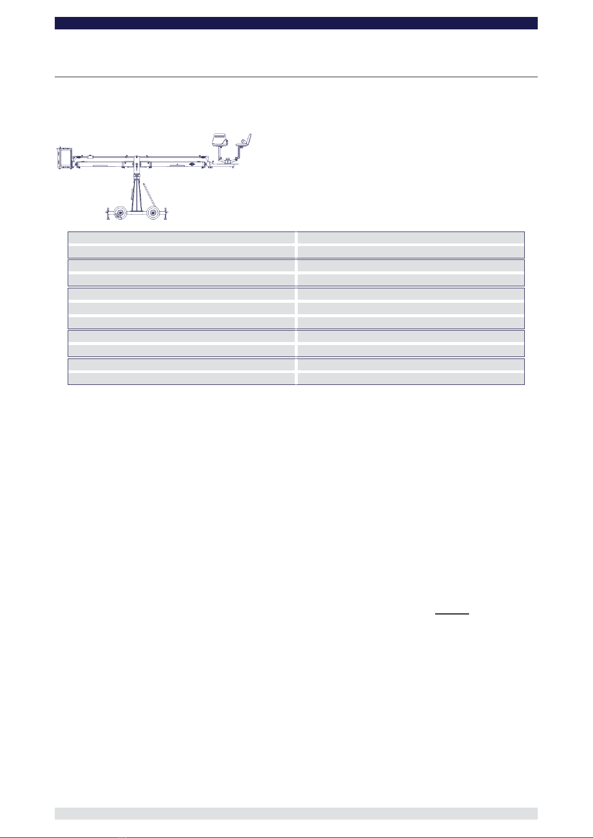
Version1......................................................................................................................7
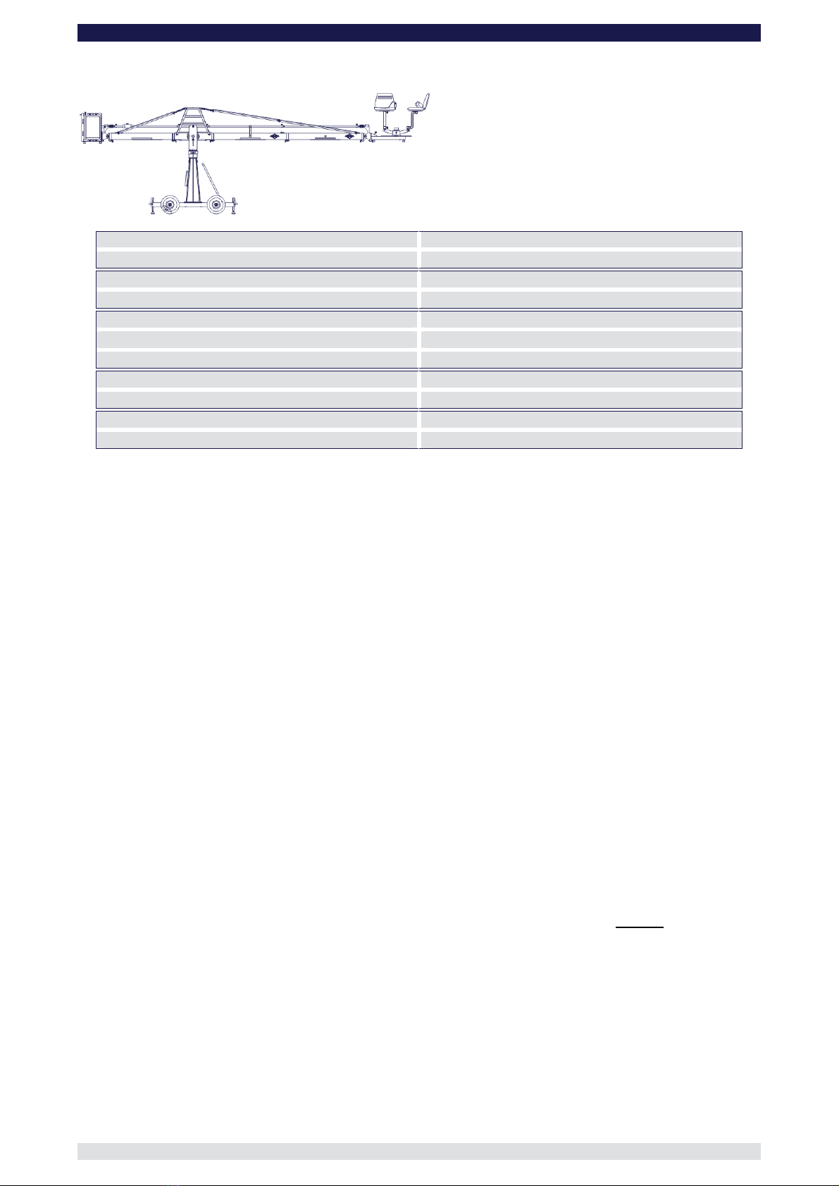
Version2......................................................................................................................8
Version3......................................................................................................................9
Version4....................................................................................................................10
Version5....................................................................................................................11
Version6....................................................................................................................12
Version7....................................................................................................................13
Version8....................................................................................................................14
Version9....................................................................................................................15
Version10..................................................................................................................15
Version11..................................................................................................................16
Version12..................................................................................................................16
Version13..................................................................................................................17
Version14..................................................................................................................17
Version15..................................................................................................................18
Version16..................................................................................................................18
Version17..................................................................................................................19
Version18..................................................................................................................20
Assembly &TechnicalSpecifications forthe Xten Versions......................................22
XtenVersion1............................................................................................................22
XtenVersion2............................................................................................................23
XtenVersion3............................................................................................................24
XtenVersion4............................................................................................................26
XtenVersion5............................................................................................................27
XtenVersion6............................................................................................................29
XtenVersion7............................................................................................................30
XtenVersion8............................................................................................................32
ParallelogramRod Support.......................................................................................34
Riggingsystem..........................................................................................................35
Double Rigging System.............................................................................................36
Lower, front rigging.....................................................................................................36
Top, front rigging........................................................................................................36
Mountingthe Extra, MiniCounterweight BucketforXtenVersions..............................38
Balancingthe crane arm...........................................................................................38
GeneralSafety..........................................................................................................39
Accessories forGF- 8 crane......................................................................................40
Mountingthe accessories...........................................................................................40
Use with GFMTrack(GF-Track)...............................................................................41
Transport trolley forthe GF-8Crane.........................................................................42
GF-8 Crane Dollies...................................................................................................43
The GF-8DoubleEndedConnectedSteeringBase....................................................44