manuals.online logo
Brands
  1. Home
  2. •
  3. Brands
  4. •
  5. Manfrotto
  6. •
  7. Camera Accessories
  8. •
  9. Manfrotto 083NW User manual

Manfrotto 083NW User manual

INSTRUCCIONES DE USO
CAMPO DE APLICACION
El pie 083NW se ha costruido para la utilización de focos potentes y aclaradores en los sectores
de iluminación cine, fotografica y conciertos.
IMPORTANTE - ISPECCIÓN DE SEGURIDAD
- Carga máxima: 45 kg
- Antes de colocar el pie asegúrese que el suelo sea lo mas horizontal posible.
- No coloque nunca el pie Wind-Up en terreno blando o suelto.
- Si utiliza un braza para focos (fig. 2) cuide de guardar bien el equilibrio
(Solo para el uso en exteriores).
- El pie ha de asegurarse con las cuerdas Art. 087WBK - (fig. 3).
COLOCACION Y
Abra el tornillo de bloqueo “A” (fig. 1).
Empuje los tirantes de las patas a la posición inferior y vuelva a fijar el tornillo “A”.
La colocación será mais fácil si primero afloja el tornillo “C”.
Si el suelo no es plano, el pie poede nivelarse con ayuda del tornillo “B”:
- aflojar el tornillo en contra del sentido de las manecillas del reloj.
- tire de la parte inferior de la pata hasta que el Wind-Up esté en posición vertical.
- fije el tornillo “B” en sentido contrario.
Es esencial que el pie esté nivelado ANTES de ponerle un equipo encima.
CARGA DE SIE
Para fijar un foco colóquelo en el zócalo 1-1/8" superior y bloquee con el tornillo “D” (fig. 2).
No coloque objetos grandes sobre el pie, como por ej. reflectores grandes porque ofrecen
grandes superficies para el ataque del viento y el pie poede volcar.
Se recomienda usar el zócalo de 1 1/8” (28mm) hembra para cargas pesadas porque da más
estabilidad.
VARIACION DE ALTURA
Antes de variar la altura del pie controle los siguiente extremas:
- esta el pie correctamente colocado y se ha tenido en cuenta la naturaleza del suelo?
- los focos o el brazo estan bien equilibrados y fijados (tornillo “D”)?
Suelte el tornillo “C” (fig. 4).
Para trabajar con la manivela “E” proceda como sigue:
- suelte el tornillo “F” en el sentido de las manecillas del reloj.
- doble la manivela hascia abajo.
- vuelva a apretar el tornillo “F” (fig. 5) para bloquear la manivela en la posición de trabajo.
Ahora podra girar la manivela “E” y se elevan las colunnas del pie.
Si surgen problemas accíonando la manivela controle los siquientes extremos:
- estan aflojado el tornillo “C”?
- el foco colocado na será demasiado pesado?
- alguna de las colunnas esta deteriorada (por ej. por el transporte)?
- a variación de la altura es obstaculizada por ramas, techos o barandillas o no se han soltado las
cuerdas de seguridad aplicadas?
Alcanzada la altura deseada bloquear el torníllo “C” en el sentido de las manecillas del reloj.
Olvide tampoco fijar el pie con los tirantes (cuerdas).
BAJAR EL PIE WIND-UP Y
Antes de proceder asegúrese que el pie o los focos no estén anganchados ni bloqueados en
alguna parte (en ramas, barandillas, etc.).
Soltar el tornillo de bloqueo “C”.
Gire la manivela “E” en contra del sentido de las manecillas del reloj hasta que la extensión de
colunna tenga la altura deseada. Vuelva a bloquear con el torníllo “C”.
Caso de surgir problemas al bajar, examine los siguientes extremos:
- estan aflojado el tornillo “C”?
- es bloqueada la variación de altura por ramas, techos o barandillas o no se han soltado las
cuerdas de seguridad aplicadas?
Caso de que la columna central telescópica desciende si lleva paso pero sin accionar la manivela,
adjustar el freno apretando el tornillo “G” (fig. 5) en sentido del reloj hasta que la columna
permanezca en su posición con el peso del equipo y el mando “C” aflojado.
Cod. 083,87 - 09/04 Copyright © 2004 Manfrotto Bassano Italy
INSTRUCTIONS
083NW
E
D
GEBRAUCHSANLEITUNG ANWENDUNGSBEREICH
Das Stative 083NW wurdet für den Einsatz von Scheinwerfern und Aufhellem für Film-, Foto- und
Konzertbeleuchtung gebaut.
WICHTIG -SICHERHEITSÜBERPRÜFUNG
- Maximales Ladegewicht: 45 kg.
- Bevor Sie das Stativ aufstellen, versichern Sie sich, das der Untergrund möglichst
horizontal ist.
- Stellen Sie das Wind-Up Stativ nie auf weichen oder losen Untergründen auf.
- Sollten Sie einen Leuchtenausleger (Abb. 2) verwenden, so achten Sie darauf, dass das
Gewicht so gut als möglich ausbalanciert ist.
- Bei Benützung im Freien sichern den Stativ mit den Sicherungsseilen (Art. 087WBK - Abb. 3)
AUFSTELLEN UND
Öffnen Sie die Blockierschraube “A” (Abb. 1). Schieben Sie die Stativbeinverstrebungen in die
unterste Position und arretieren Sie die Schraube “A” wieder. Das Aufstellen geht Ihnen leichter
von der Hand, wenn Sie die Schraube“C” zuerst lösen.
Sollte der Boden nicht eben sein, so kann das Stativ mit Hilfe der Schraube “B” ausnivelliert
werden:
- lösen Sie die Schraube im Gegenuhrzeigersinn
- ziehen Sie den unteren Teil des Stativbeines heraus, bis das Wind-Up senkrecht steht.
- arretieren Sie die Schraube “B” im Uhrzeigersinn
Es ist wichtig, dass das Stativ senkrecht ausgerichtet wird, BEVOR es beladen wird.
BELADEN DES STATIVS
Um einen Scheinwerfer zu befestigen, setzen Sie ihn in den 1-1/8” Sockel am Stativende und
blockieren die Arretierschraube “D” (Abb. 2). Setzen Sie keine grossen Gegenstände wie z.B.
Grossreflektoren auf das Wind-Up Stativ, da diese eine grosse Angriffsfläche für den Wind bieten
und das Stativ zum Kippen bringen könnten.
Aus Gründen der höheren Stabilität ist zu empfehlen, dass Sie den 28 mm (1 1/8”) Socket
benutzen, wenn schwere Gegenstände aufgesetzt werden.
HÖHENVERSTELLUNG
Bevor Sie die Höhe des Stativs verstellen, kontrollieren Sie die folgenden Punkte:
- ist das Stativ richtig aufgestellt und wurde auf die Bodenbeschaffenheit geachtet?
- sind die Scheinwerfer oder Ausleger richtig ausbalanciert und blockiert (Schraube “D”)?
Lösen Sie die Blockierschraube “C” (Abb. 4) im Gegenuhrzeigersinn.
Um die Kurbel “E” zu lösen gehen Sie wie folgt vor:
- lösen Sie die Schraube “F” im Uhrzeigersinn
- kippen Sie die Kurbel nach unten.
- ziehen Sie die Schraube “F” im Gegenuhrzeigersinn an (fig. 5), damit die Kurbel in der
Arbeitsposition blockiert wird.
Jetzt können Sie die Kurbel “E” im Uhrzeigersinn drehen und die Stativsäulen werden
ausgefahren.
Falls beim Kurbeln Probleme auftauchen, so kontrollieren Sie folgende Punkte:
- ist die Schraube “C” gelöst?
- ist der aufgesetzte Scheinwerfer nicht zu schwer?
- weist eine der Stativsäulen Beschädigungen (z.B. vom Transport) auf?
- wird die Höhenverstellung durch Äste, Decken oder Balustraden blockiert oder sind d allfällig
angebrachte Sicherungsseile nicht gelöst worden?
Wenn die gewünschte Höhe erreicht ist, so blockieren Sie die Schraube “C” im Uhrzeigersinn.
Vergessen Sie auch nicht, das Stativ mit den Sicherungsseilen zu befestigen.
TIEFERSTELLEN DES WIND-UP STATIVS UND
Bevor Sie mit dem Verstellen beginnen, versichern Sie sich, daß das Stativ oder die. Scheinwerfer
nirgendwo einhängen oder blockiert werden können (an Ästen, Balustraden, etc). Lösen Sie die
Blockierschraube “C” im Gegenuhrzeigersinn.
Drehen Sie die Kurbel “E” in Gegenuhrzeigersinn, bis der Säulenauszug die gewünschte Höhe
erreicht hat. Ziehen Sie danach die Schraube “C” wieder an.
Falls beim Runterkurbeln Probleme auftauchen, so kontrollieren Sie folgende Punkte:
- ist die Schraube “C” gelöst?
- wird die Höhenverstellung durch Äste, Decken oder Balustraden blockiert oder sind die allfällig
angebrachte Sicherungsseile nicht gelöst worden?
Sollte sich bei beladenem Zustand die Mittelsäule absenken, ohne dass dabei die Kurbel betätigt
wird, so muss die Bremse justiert werden. Drehen Sie dazu die Schraube “G” (Abb. 5) im
Uhrzeigersinn, bis die beladene Säule (mit gelöste Schraube “C”) sicher arretiert ist.
4
4 5
1 2
2
4
4 5
1 2
2
C
F
E
GB
INSTRUCTIONS
PURPOSE RANGE
The 083NW stand is designed to support luminaires for film and broadcast productions on
location or in the studio.
IMPORTANT - SAFETY INSPECTION
- Maximum load: 45 kg
- The stand should only be set up on a horizontal level surface.
- The stand must be set up on firm ground capable of taking both the weight of the stand
and its load without sinking in.
- All loads should be balanced especially when using T Bars.
- For use in the open air secure the stand with safety cables (Art. 087WBK - fig. 3)
SETTING UP &
Verify that the base is open at all by pushing the stand brace till the bottom position and locking it
with locking screw “A” (fig. 1).
The operation is easier with the stand columns folded.
The stand incorporates one adjustable length leg (fig. 2) to compensate for differences in ground
level or step:
- open locking screw “B”
- extend the leg until the stand reaches the vertical position
- lock again screw “B”.
It is essential that the stand is levelled BEFORE loading is with equipment.
LOADING THE STAND
Open locking screw “D” (fig. 2) before inserting the spotlight spigot into the 1-1/8” (28 mm) socket
at the top of the stand. To secure in position lock screw “D” (fig. 2).
Only use the stand for supporting large reflectors on location in combination with the safety cable
(Art. 087WBK) as the stand could tip over in windy conditions.
It is recommended that you use the 1 1/8” (28 mm) female socket for heavy loads as it provides
more stability.
HEIGHT ADJUSTMENT
Before you adjust the height check the following:
- is the stand set up correctly and has the condition of the ground been taken into account?
- are the spotlights or extension arms correctly balanced and locked (Screw “D”)?
Loosen the locking screw “C” (fig. 4) by turning anti-clockwise.
To release crank “E” proceed as follows:
- loosen screw “F” turning clockwise.
- tip the crank downwards.
- tighten screw “F” turning it anti-clockwise to ensure the crank handle is locked into the
operational position.
You can now turn crank handle “E”clockwise to raise the columns.
If problems arise when cranking, check the following:
- have screw “C” been loosened.
- is the load on the stand to heavy (max 45 kg).
- is there any sign of damage to the stand (eg. caused during transportation).
- is the height adjustment being restricted by a branch, ceiling etc or have any of the safety cables,
where fitted, not been released?
When the desired height has been achieved, lock screw “C” (fig. 4) by turning it clockwise.
Do not forget to secure the stand with safety cables on location.
HEIGHT ADJUSTMENT &
Before you begin, ensure there are no ohstructions that cause the unit to jam (branches,
balustrades etc)
Loosen screw “C” (fig. 4) by turning it anti-clockwise.
Turn the crank handle anti-clockwise until the stand is at the desired height.
Lock screw “C”.
If problems arise when cranking the stand down, check:
- have screw “C” been loosened.
- are there any obstructions preventing the stand from lowering.
In the event that the telescopic centre column descends when loaded but without setting into
action the crank handle, adjust the brake by tightening the screw “G” (fig. 5) clockwise until the
column remains in position with equipment loaded and knob “C” loosened.
FI
INSTRUCTIONS
UTILISATION
Le pied 083NW est conçus pour être utilisés avec des èclairages.
Pour utilisation en cinema, vidéo, photo et concert.
IMPORTANT - CONTRÔLE DE SÉCURITÉ
- Poids admissible: 45 kg
- Vérifiez avant tout que le sol soit le plus horizontal possible.
- No jamais poser le pied sur un sol meuble ou friable.
- Si vous utilisez une barre d’extension, assurez-vous que la charge ne dépasse pas
lepoids admissible et qu’elle soit parfaitement répartie.
- en situation extérieure, le pied est haubané avec des câbles de sécurité (Art. 087WBK,
fig. 3)
MONTAGE ET
Desserrez la vis de blocage “A” (fig. 1), poussez les entretoises jusqu’à la position la plus basse,
puis resserrez la vis de blocage “A”.
La mise en place e sera facilitée si vous desserrez dans un premier temps la vis “C”.
Si le sol n’est pas à niveau, le pied peut être redressé à l’aide de la jambe de mise à niveau en
actionnant le bouton “B”:
- desserrez le bouton en le tournant dans le sens inverse des aiguilles d’une montre.
- tirez la section inférieure de la jambe jusqu’à ce que la colonne centrale soit parfaitement
verticale.
- puis resserrez le bouton “B” enle tournant dans le sens des aiguilles d’une montre.
Il est indispensable que le pied soit à niveau avant de le charger.
FIXATION DE L’ECLAIRAGE
Pour fixer un spot, inserrez le dans l’adaptateur femelle 1-1/8” (28mm) à I’extrémité de la section
du pied, puis serrez la vis “D” (fig 2).
Ne fixez pas de grands réflecteurs, ou autres grandes surfaces, car la prise au vent (ou le porte-
à-faux) serait importante et pourrait renverser le pied.
Nous vous recommandons l’utilisation de la fixation femelle 1 1/8” (28 mm) pour les charges
importantes, celle- ci assurant une plus grande stabilité.
REGLAGE DE LA HAUTEUR
Avant tout, assurez vous que:
- le pied est correctement monté
- le sol est ferme
- la charge est parfaitement équilibrée et que sa fixation est bloquée (vis “D”)
Desserrez, la vis de blocage “C” (fig. 4) en les tournant dans le sens inverse des aiguilles d’une
montre.
Pour mettre en place la manivelle “E”:
- desserrez la vis “F” en la tournant dans le sens des aiguilles d’une montre
- renversez la manivelle vers le bas
- resserrez la vis “F” en la tournant vers la gauche (fig. 5), ainsi la manivelle est en position de
travail.
Vous pouvez à présent l’actionner dans le sens des aiguilIes d’une montre pour monter les
sections téléscopiques. Si un problème survient lorsque vous tournez la manivelle, contrôlez que:
- la vis “C” est desserrée
- le poids de l’éclairage ne dépasse pas le poids admissible du pied
- l’une des sections téléscopiques n’a pas été endommagé lors du transport
- des obstacles (branchages, plafond, balustrade) n’obstruent pas la montée de l’une des
sections, et que les câbles de sécurité ne sont pas bloqués.
Lorsque la hauteur souhaitée est atteinte, rebloquez en tournant le bouton “C” (fig. 4) dans le
sens des aiguilles d’une montre.
N’oubliez pas d’assurer le pied avec les câbles de sécurité.
DESCENTE DU PIED WIND UP ET
Avant d’abaisser les sections, vérifiez que:
- aucun objet n’obstrue le passage ou ne s’accroche à l’éclairage ou au pied.
Desserrez dans le sens inverse des aiguilles d’une montre la vis de blocage “C” (fig. 4), et tournez
la manivelle de droite à gauche jusqu’à obtenir la hauteur désirée, ensuite, resserrez la vis “C”.
Si un problème surviènt pendant la descente des sections vérifiez que:
- la vis “C” soit bien desserrée
- aucun obstacle ne bloque le réglage de la hauteur (branches, balustrade, câbles de sécurité non
libres).
Dans l’éventualité où les colonnes centrales téléscopiques descendraient sous le poids d’une
charge sans que vous tourniez la manivelle, ajustez le frein en serrant la vis “G” (fig. 5) dans le
sens des aiguilles d’une montre jusqu’à ce que la colonne chargée reste en position, le bouton
“C” devant être desserré.
ISTRUZIONI PER L’USO
CAMPO D’IMPIEGO
Lo stativo 083NW è stato concepito per supportare proiettori e fari per l’illuminazione di studi
foto-cinematografici e sale da concerti.
NORME PER L’UTILIZZO IN SICUREZZA
- Carico massimo applicabile: 45 kg.
- Prima di posizionare il Wind Up assicurarsi che la superficie d’appoggio sia il più
possibile orizzontale.
- Evitare assolutamente di posizionare lo stativo su superfici ove esista la possibilità che
i piedini sprofondino.
- Il carico deve essere sempre bilanciato specie se costituito da barre per più riflettori.
- Se usato in esterno, controventare lo stativo (fig. 3) fissando i cavi (Art. 087WBK non in
dotazione) per mezzo degli appositi moschettoni.
POSIZIONAMENTO E
Assicurarsi che la base venga ben aperta e che la crociera sia bloccata sul punto più basso
con l’apposita manopola “A” (fig. 1).
Per facilitare l’operazione abbassare completamente la colonna dello stativo agendo sulla
manopola “C”.
Lo stativo va livellato, nel caso non lo sia agire sulla manopola “B” (fig. 1) posta sulla
gambetta:
- ruotare in senso antiorario la manopola
- estendere la gambetta fino a raggiungere la perfetta verticalità delle colonne
- bloccare in senso orario
Il livellamento va effettuato assolutamente PRIMA di caricare l’attrezzatura sullo stativo.
CARICAMENTO
Bloccare sempre il carico con l’apposita leva “D” (fig. 2). In presenza di vento anche se debole
evitare di caricare sullo stativo schermi o comunque carichi con grandi superfici.
Dei due attacchi femmina (ø5/8” e ø1 1/8”), utilizzare, se possibile, sempre l’attacco da 1 1/8”
che garantisce maggiore stabilità all’attrezzatura pesante.
SOLLEVAMENTO
Prima di iniziare le operazioni di sollevamento del carico verificare ulteriormente che:
- lo stativo sia correttamente posizionato
- il carico sia bilanciato e fissato con l’apposita leva “E”.
Allentare la manopola “C” (fig. 4) ruotandola in senso antiorario. Ribaltare la manovella “E”:
- ruotare in senso orario la ghiera “H”
- tirare la manovella nel senso della freccia
Bloccare in posizione di lavoro la manovella ruotando la ghiera “F” in senso antiorario (fig. 5).
Sollevare il carico girando la manovella “E” in senso orario.
Nel caso si riscontri una notevole difficoltà nel far salire il carico verificare che:
- sia stata allentata la manopola di serraggio “C”
- il carico non sia superiore alla portata prevista
- la colonna o la scatola di sollevamento non siano state danneggiate durante il trasporto dello
stativo
- che sopra al carico non vi sia un ostacolo che ne impedisca la salita o i cavi di
controventatura non siano impigliati.
Raggiunta l’altezza desiderata serrare la manopola “C” ruotandola in senso orario ed ancorare
saldamente i cavi al suolo.
ABBASSAMENTO E
Prima di iniziare le operazioni di discesa assicurarsi che il carico non tocchi o sia agganciato a
strutture adiacenti e che comunque abbia la possibilità di discendere liberamente.
Allentare la manopola di serraggio “C” ruotandola in senso antiorario.
Abbassare completamente la colonna ruotando in senso antiorario la manovella “E”.
Richiudere la manopola “C”.
Nel caso si riscontri un’eccessiva resistenza nella discesa della colonna arrestarsi subito e
verificare che:
- la manopola “C” sia stata allentata
- che il carico non sia impigliato o tocchi su qualche sporgenza.
Nel caso invece che la colonna scenda sotto l’azione del carico senza che sia azionata la
manovella “E”, regolare il freno per la discesa agendo sulla vite “G” (fig. 5) avvitandola (senso
orario) fino a che la colonna rimane ferma con attrezzatura caricata e manopola “C” allentata.
4
4 5
1 2
2
2
4
4 5
1 2
2
4
4 5
1 2
2
D
D
B
A
E
D
C
1
3 4
F
E
G
5
Other Manfrotto Camera Accessories manuals

Manfrotto 503HDV User manual

Manfrotto

Manfrotto 503HDV User manual

Manfrotto 249 User manual

Manfrotto

Manfrotto 249 User manual

Manfrotto MKCONVR User manual

Manfrotto

Manfrotto MKCONVR User manual

Manfrotto 547B User manual

Manfrotto

Manfrotto 547B User manual

Manfrotto MKBFRLA-BH User manual

Manfrotto

Manfrotto MKBFRLA-BH User manual

Manfrotto 561B User manual

Manfrotto

Manfrotto 561B User manual

Manfrotto 303 User manual

Manfrotto

Manfrotto 303 User manual

Manfrotto 501HDV User manual

Manfrotto

Manfrotto 501HDV User manual

Manfrotto 562B User manual

Manfrotto

Manfrotto 562B User manual

Manfrotto 475 User manual

Manfrotto

Manfrotto 475 User manual

Manfrotto MTWISTGRIPH User manual

Manfrotto

Manfrotto MTWISTGRIPH User manual

Manfrotto MVM250A User manual

Manfrotto

Manfrotto MVM250A User manual

Manfrotto 804RC2 User manual

Manfrotto

Manfrotto 804RC2 User manual

Manfrotto 625 User manual

Manfrotto

Manfrotto 625 User manual

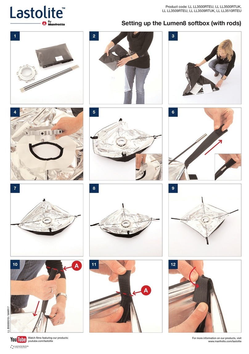
Manfrotto Lastolite Lumen8 User instructions

Manfrotto

Manfrotto Lastolite Lumen8 User instructions

Manfrotto MT290DUA3 User manual

Manfrotto

Manfrotto MT290DUA3 User manual

Manfrotto 322RS User manual

Manfrotto

Manfrotto 322RS User manual

Manfrotto 502 User manual

Manfrotto

Manfrotto 502 User manual

Manfrotto 494 User manual

Manfrotto

Manfrotto 494 User manual

Manfrotto 494RC2 User manual

Manfrotto

Manfrotto 494RC2 User manual

Manfrotto Lastolite XpoBalance User manual

Manfrotto

Manfrotto Lastolite XpoBalance User manual

Manfrotto 361 User manual

Manfrotto

Manfrotto 361 User manual

Manfrotto Lumimuse User manual

Manfrotto

Manfrotto Lumimuse User manual

Manfrotto 160 User manual

Manfrotto

Manfrotto 160 User manual

Popular Camera Accessories manuals by other brands

walimex 16 angle instruction manual

walimex

walimex 16 angle instruction manual

Dewey DCS1 Assembly guide

Dewey

Dewey DCS1 Assembly guide

Sunpak PRO 723B Specifications

Sunpak

Sunpak PRO 723B Specifications

Phottix Nuada R3 instruction manual

Phottix

Phottix Nuada R3 instruction manual

Mastervolt BATTERY MATE 1602 user manual

Mastervolt

Mastervolt BATTERY MATE 1602 user manual

Zhiyun WEEBILL 3 quick start guide

Zhiyun

Zhiyun WEEBILL 3 quick start guide

Philips R03B4A70 Specification sheet

Philips

Philips R03B4A70 Specification sheet

Energizer IEC-LR43 Product data sheet

Energizer

Energizer IEC-LR43 Product data sheet

JVC CB-A270 instructions

JVC

JVC CB-A270 instructions

Nikon EN-EL3 instruction manual

Nikon

Nikon EN-EL3 instruction manual

Steadicam M-1 Operator's manual

Steadicam

Steadicam M-1 Operator's manual

Shorai LFX series user guide

Shorai

Shorai LFX series user guide

Philips PowerLife LR6PS12C Specifications

Philips

Philips PowerLife LR6PS12C Specifications

Wisenet SHD-3000F1 installation manual

Wisenet

Wisenet SHD-3000F1 installation manual

FLIR SR PT specification

FLIR

FLIR SR PT specification

Guilin Feiyu Technology G5 Setting manual

Guilin Feiyu Technology

Guilin Feiyu Technology G5 Setting manual

10Bar E-500 user manual

10Bar

10Bar E-500 user manual

Nodal Ninja EZ-Leveler II Fanotec Quick reference guide

Nodal Ninja

Nodal Ninja EZ-Leveler II Fanotec Quick reference guide

manuals.online logo
manuals.online logoBrands
  • About & Mission
  • Contact us
  • Privacy Policy
  • Terms and Conditions

Copyright 2025 Manuals.Online. All Rights Reserved.