GFS 1000 Guide

ITEM
SAFETY
SPECIFICATION
GENERAL OPERATION MANUAL
MAINTENANCE
EXPLODED DRAWING AND PARTS LIST
PAGE
1
6
8
16
19
MODEL GFS 1000
GAS CONCRETE NAILER
SAFETY OPERATION MANUAL
E: sales@gfsfasteningsystems.com
T: +61 (7) 38615767
Fax: +61 (7) 33503584
FASTENING SYSTEMS
GFS

IMPORTANT INFORMATION TO KNOW. PLEASE
READ BEFORE USE.
Read and understand tool labels
and all of operating instructions,
safety precautions and warnings in
this manual before operating or
maintaining this nailer.
Failure to follow warnings could result in DEATH
or SERIOUS INJURY.
Most accidents that result from the operation and
maintenance of Nailers are caused by the failure
to observe basic safety rules or precautions. An
accident can often be avoided by recognizing
a potentially hazardous situation before it
occurs, and by observing appropriate safety
procedures.
Basic safety precautions are outlined in the
“SAFETY” section of this Manual
Hazards that must be avoided to prevent bodily
injury or machine damage are identified by
DANGERS and WARNINGS on the Nailer and in
this Manual
Never use this Nailer for applications other than
those specified in this Manual.
DEFINITIONS OF SIGNAL WORDS
DANGER indicates an imminent hazardous situation
which, if not avoided, will result in death
or serious injury.
WARNING indicates a potentially hazardous
situation which, if not avoided, could
result in death or serious injury.
CAUTION indicates a pot entially hazardous
situation which, if not avoided, may
result in minor or moderate injury, or
may cause machine damage.
NOTE emphasizes essential information.
EXPLANATION OF THE FUNCTION OF THE GFS
NAILER
This tool has a FULL SEQUENTIAL ACTUATION
MECHANISM (on the nailer body mark del operator ).
First, press the push lever ( push lever be called
apart of the full sequential actuation mechanism)
against the workpiece; press down of the nailer,
and then pull the triggerto drive the nail. Follow
the same sequence tocontinue driving nails after
the push lever and trigger are return back in place.
SAFETY
IMPORTANT SAFETY INSTRUCTIONS FOR
USING NAILERS
READ ALL INSTRUCTIONS
This Nailer is powered by internal
combustion device.
This Nailer shall only be used with
dispensers for combustible gas
which are listed in this manual.
DANGER
1. OPERATORS AND OTHERS IN WORK AREA
MUST WEAR SAFETY GLASSES WITH SIDE
SHIELDS.
When operating the Nailer, always
wear safety glasses with side
shields, and make sure others in
work area wear safety glasses.
Safety glasses must conform to the requirements
of American National Standards Institute,
ANSI Z87.1 and provide protection against flying
particles both from the front and side.
T h e e m p lo y e r mu st e n f or c e the use of
safety glasses by the Nailer operator and
others in work area.
2. NEVER USE IN PRESENCE OF FLAMMABLE
LIQUIDS ORGASES.
This Nailer must not be used in a
combustible envir onment or in
presence of flammable liquids or
gases, e.g. lacquer, paint, benzine,
thinner or gasoline.
This Nailer produces hot exhaust gases that
may ignite flammable materials and produces
sparks during operation.
3. DO NOT TOUCH AROUND THE EXHAUST
OUTLET.
This Nailer produces hot exhaust
gases that may flammable materials.
The pus h l ev e r and nose will
become hot and get heated up after
prolonged or rapid use.
Do not touch with bare hands.
4. EXPLOSION AND FIRE HAZARD.
The fuel cell is an aerosol dispensers
with flammable contents.
Pressured cont ainer and the
propellant will remain in the fuel cell.
Faillure tofollow instructions may
result in explosion or fire.
1

120°F MAX
(50℃)
2
Keep the Nailer, fuel cells and battery
away from sunshine and from
tem per ature exceeding 120°F
(50°C).
Fuel cell and/or battery may burst,
releasing flammable gas.
Do not pierce or burn the container,
even after use.
Do not incinerate, refill, reclaim
or recycle the fuel cell.
Do not spray to a naked flame or any
incandescent material.
Keep away from ignition sources
No smoking.
Keep out of the reach of children.
WARNING
5. NEVER POINT TOOL AT YOURSELF OR OTHERS
IN WORK AREA.
Always assume the Nailer contains
fasteners.
Never point the Nailer at yourself or
others, whether it contains fasteners
or not.
If fasteners are mistakenly driven, it can lead to
severe injuries.
Never engage in horseplay with the Nailer.
Respect the Nailer as a working implement.
6. KE E P FI NGE RS AWAY FROM TRIGGER
W H E N N O T DRI V I N G F AS TE NE RS T O
AVOID ACCIDENTAL FIRING.
Never carry the Nailer with finger on trigger
since you could drive a fastener unintentionally
and injure yourself or someone else.
Always carry the Nailer by the handle only.
7. ALWAYS WEAR EAR AND HEAD PROTECTION.
Always wear ear protection to protect your ears
from loud noise.
Always wear head protection to protect your head
from flying objects.
8. USE OUTSIDE OR WELL-VENTILATED AREAS.
This Na iler shall not be used in
enclosed or poorly ventilated areas.
This Nailer exhausts carbon monoxide
which is a danger to health when
inhaled.
Do not inhale.
9. STORE NAILER PROPERLY WITH FUEL CELL
AND BATTERY REMOVED.
When not in use, the Nailer, fuel cell and battery
should be store in tool case and in a dry place.
Store indoors at temperature 41°F (5°C) ~ 77°F(25°C).
Keep the Nailer, fuel cell and battery out of
direct sunlight and out of in a vehicle.
Keep out of reach of children.
Look the storage area.
10. KEEP WORK AREA CLEAN.
Cluttered areas invite injuries. Clear all work
areas of unnecessary tools, debris, furniture, etc.
11. KEEP VISITORS AWAY.
Do not let visitors handle the Nailer.
All visitors should be kept safely away from
work area.
12. DRESS PROPERLY.
Do not wear loose clothing or jewelry as they can
be caught in moving parts.
Rubber g loves an d nonskid footwear are
recommended when working outdoors.
Wear protective hair covering to contain long hair.
13. CHECK PUSH LEVER BEFORE USE.
Remove fuel cell and battery, and then make
sure the push lever operates properly. Never use
the Nailer unless the push lever is operating
properly, otherwise the Nailer could drive a
fastener unexpectedly. Do not tamper with or
remove the push lever, otherwise the push lever
becomes inoperable.
14. KEEP ALL SCREWS AND COVERS TIGHTLY
IN PLACE.
Keep all screws and covers tightly mounted.
Check their condition periodically.
Never use the Nailer if parts are missing or
damaged.
15. DO NOT LOAD FASTENERS WITH TRIGGER
OR PUSH LEVER DEPRESSED.
When loading fasteners into the Nailer,
1) do not depress the trigger;
2) do not depress the push lever;
3) keep the Nailer pointed downward.
16. KEEP FACE, HANDS AND FEET AWAY FROM
FIRING HEAD DURING USE.
Never place your face, hands or feet closer than
8 inches (200 mm) from the firing head.
A serious injury can result if the fasteners are
deflected by the workpiece, or are driven away
from the point of entry.

3
17. PLACE NAILER PROPERLY ON WORKPIECE.
Do not drive fasteners on top of other fasteners
or with the Nailer at too steep of an angle; the
fasteners can ricochet and hurt someone.
18. DO NO T DRIVE FASTENERS INTO THIN
BOARDS OR NEAR CORNERS AND EDGES
OF WORKPIECE.
The fasteners can be driven through or away
from the workpiece and hit someone.
19. NEVER DRIVE FASTENERS FROM BOTH
SIDES OF A WALL AT THE SAME TIME.
The fasteners can be driven into and through
the wall and hit a person on the opposite side.
20. CHECK FOR LIVE WIRES.
Avoid the risk of severe electrical shock by
checking for live electrical wires that may be
hidden by walls, floors or ceilings. Turn off the
breaker switch to ensure there are no live wires.
21. DO NOT OVERREACH.
Keep proper footing and balance at all
times. Do not allowed operate the nailer
on the scaffold and ladder.
22. NEVER USE NAILER WHICH IS DEFECTIVE
OR OPERATING ABNORMALLY.
If the Nailer appears to be operating unusually,
making strange noises, or otherwise appears
defective, stop using it immediately and arrange
for repairs by a *)6 authorized service center.
23. TAKE FUEL CELL AND BATTERY OUT OF
NAILER WHEN:
1) doing maintenance and inspection;
2) clearing a jam;
3) it is not in use;
4) leaving work area;
5) moving it to another location;
6) handing it to another person.
Never attempt to clear a jam or repair the Nailer
unless you have taken fuel cell and battery out
of the Nailer and removed all remaining fasteners
from the Nailer.
The Nailer should never be left unattended since
people who are not familiar with the Nailer might
handle it and injure themselves.
24. KEEP ALERT.
Operate the nailer only in good physical and mental
state.
Do not operate the Nailer when you are tired.
The Nailer should never be used by you if you
are under the influence of alcohol, drugs or
medication that makes you drowsy.
25. HANDLE NAILER CORRECTLY.
Operate the Nailer according to this Manual.
Never allow the Nailer to be operated by children,
individuals unfamiliar with its operation or
unauthorized personnel.
26. NEVER USE NAILER FOR APPLICATIONS
OTHER THAN THOSE SPECIFIED IN THIS
MANUAL.
27. HANDLE NAILER CAREFULLY.
Do not drop the Nailer or strike the Nailer against
hard surfaces; and do not scratch or engrave
signs on the Nailer. Handle the Nailer carefully.
28. MAINTAIN NAILER WITH CARE.
Keep the Nailer clean and lubricated for better
and safer performance.
29. U SE ONL Y PA RTS, A CC ESSORIES OR
FASTENERS SUPPLIED OR RECOMMENDED
BY *)6.
Unauthorized parts, accessories, or fasteners
may void your warranty and can lead to malfunction
and resulting injuries.
Only service personnel tr ained by *)6,
distributor or employer trained personnel shall
repair the Nailer.
30. NEVER MODIFY OR ALTER A NAILER.
Doing so may cause it to malfunction and personal
injuries may result.

4
FUEL CELL IMPORTANT SAFETY INSTRUCTIONS
DANGER
■ Fuel cell, fuel and propellant are flammable
under pressure.
Explosion / Fire Hazard
M ust to follo w all in structions
otherwise may result in fire and
explosion when handling dispensers
for combustible gas for the purpose
of storage, transportation, inserting into and
taking out of the tool and disposal.
■ Do not smoke when handling the fuel cell.
WARNING
Do not inhale its contents.
In case of being inhaled ; the person
affected should be taken into the
open air and brought into a comfortable
position.
Expanding gases cause low temperatures.
Fluid gases might cause injuries when getting
in touch with skin or eyes.
In case of contact with skin ; wash the contact
surface carefully with warm water and soap and
apply a skin cream when dry.
In case of contact with eyes ; rinse the open eyes
under running water.
Contact a doctor if necessary.
Store in well-ventilated area.
Store under 41°F (5°C) ~77°F (25°C) (e.g.
Do not store under the direct sunlight or in a
vehicle).
Do not expose to an open flame and sparks.
Do not puncture or open the fuel cell.
Do not refill, reclaim or recycle the fuel cell.
Dispose of according to local regulations for
aerosol products.
Do not dispose of fuel cell with other scrap for
recycling.
Keep out of reach of children.
IMPORTANT SAFETY INSTRUCTIONS FOR
BATTERY CHARGER
WARNING
Death or serious bodily injury could result from
improper or unsafe use of battery chargers.
To avoid these risks, follow these basic safety
instructions:
READ ALL INSTRUCTIONS
1. This manual contains is important safety and
operating instructions for battery charger Model
504.4.04.013.XX.
2. Before using battery charger, read all instructions
and cautionary markings on (1)nailer,(2) battery
charger, (3) battery.
3. To reduce risk of injury, only use *)6 rechargeable
battery type 504.4.04.011.01 . Other type of
batteries may burst causing personal injury and
damage.
4. Do not expose battery charger to rain or snow.
5. Use of an attachment not recommended or sold
by the battery charger manufacturer may result
in a risk of fire, electric shock, or injury to persons.
6. To reduce risk of damage to electric plug and
cord, pull by plug when disconnecting battery
charger.
7. Make sure cord is located so that it will not be
stepped on, tripped over, or otherwise subjected
to damage or stress.
8. An extension cord should not be used unless
absolutely necessary.
Use of improper extension cord could result in a
risk of fire and electric shock. If extension cord
must be used make sure:
a) That blades of extension cord are the same
number, size, and shape as those of plug
on battery charger;
b) That extension cord is properly wired and in
good electrical condition;
c) That wire size is large enough for AC ampere
rating of battery charger as specified in table 1.

5
Table 1
RECOMMENDED MINIMUM AWG SIZE FOR
EXTENSION CORDS FOR BATTERY CHARGERS
AC Input Rating Amperes AWG Size of Cord
Equal to or but less than Length of Cord, Feet (Meter)
greater than 2.5(7.5) 50(15) 100(30) 150(45)
0 2 18 18 18 16
2 3 18 18 16 14
3 4 18 18 16 14
If the input rating of a battery charger is given in
watts rather than in amperes, the corresponding
ampere rating is to be determined by dividing the
wattage rating by the voltage rating-for example:
1,200 watts/120volt=10 Amperes
9. Do not operate battery charger with damaged
cord or plug ,should replace them immediately.
10. Do not operate battery charger if it has received
a sharp blow, been dropped, or otherwise damaged
in any way; take it to a qualified serviceman.
11. Do not disassemble battery charger; take it to a
qualified serviceman when service or repair is
required.
Incorrect reassembly may result in a risk of
electric shock or fire.
12. To reduce risk of electric shock, unplug charger
from receptacle before attempting any maintenance
or cleaning. Removing the battery will not reduce
this risk.
13. Please read this Manual before using the battery
charger.
IMPORTANT SAFETY INSTRUCTIONS FOR USE
OF THE BATTERY AND BATTERY CHARGER
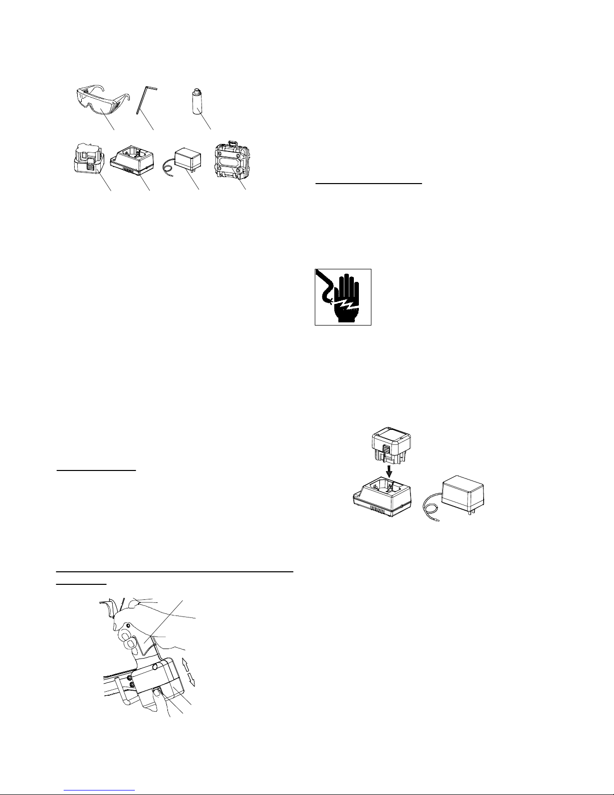
You must charge the battery before you use the
Nailer. Before using the model 503.1.16.001.01
battery charger, be sure to read all instructions and
cautionary statements on the battery and in this
manual.
R EM EM BER : ONLY US E *)6 B AT TE RY
TYPE503.1.10.001.01.
OTHER TYPES OF BATTERIES MAY BURST
AND CAUSE INJURY!
Follow these instructions to avoid the risk of injury:
WARNING
Improper use of the battery or battery charger
can lead to serious injury. To avoid these injuries:
1. DO NOT disassemble the battery.
2. DO NOT incinerate the battery, even if it is
damaged or is completely worn out.
The battery can explode in a fire.
3. DO NOT short-circuit the battery.
4. DO NOT insert any objects into the battery
charger's air vents. Electric shock or
damage to the battery charger may result.
5. DO NOT charge outdoors. Keep the battery away
from direct sunlight and use only where
there is low humidity and good ventilation.
6. DO NOT charge when the temperature is below
50°F (10°C) or above 104°F (40°C).
7. DO NOT connect two battery chargers together.
8. DO NOT insert foreign objects into the hole for
the battery or the battery charger.
9. DO NOT use a booster transformer when charging.
10.DO NOT use an engine generator or DC power
to charge.
11. DO NOT store the battery or battery charger in
places where the temperature may
reach or exceed 104°F (40°C).
12. MUST TO DO operate charger on standard
household electrical power (120 volts).
Using the charger on any other voltage
may overheat and damage the charger.
13. MUST TO DO wait at least 15 minutes between
charges to avoid overheating the
charger.
14. MUST TO DO disconnect the power cord from
its receptacle and cut off the charger
power when the charger is not in use.
DISPOSAL OF THE EXHAUSTED BATTERY
WARNING
Do not dispose of the exhausted battery. The
battery must explode if it is incinerated. The
product that you have purchased contains a
rechargeable battery. The battery is recyclable.
At the end of it's useful life, under various state
and local laws, it may be illegal to dispose of
this battery into the municipal waste stream.
Check with your local solid waste officials for
details in your area for recycling options or proper
disposal.
EMPLOYER'S RESPONSIBILITIES
1. Ensure that this MANUAL is available to operators
and personnel performing maintenance.
2. Ensure that Nailers are used only when operators
and others in work area are wearing EYE PROTECTOR.
3. Enforce the use of EYE PROTECTOR by operators
and others in work area.
4. Keep Nailers in safe working order.
5. Maintain Nailers properly.
6. Ensure that Nailers which require repair are not
further used before repair.
SAV E TH ESE MA NU AL A ND MAK E THEM
A VA ILABLE TO OTHER USERS AND OWNERS
OF THIS TOOL!

6
SPECIFICATION
1.GAS CONCRETE NAILER
TYPE GSN40-30 GSN40-40
Type of power Piston reciprocating
Applicable nails See 2. Available Nails.
Nail Capacity 32 nails (3- strip) 42 nails(4- strip)
Ambient temperature -5 ℃~ 50℃(23℉to 120℉)
Dimensions 14.17 "(L)×14.88"(H)×4.37"(W) 16.53"(L)×14.88"(H)×4.37"(W)
360mm (L)×378mm(H)×111mm(W) 420mm(L)×378mm(H)×111mm(W)
Weight 7.5lbs. (3.4kg Include battery ) 7.7lbs.(3.5kg Include battery )
Cycle Rate 2 ~3 nails/second
Battery Pack NiMH 6V 1.5Ah
2.Available Nails
Plastic strip nails MIN MAX
.250 "(6.3mm) .250"(6.3mm)
.102 "(2.6mm) .120 "(3.0mm)
NOTE:
Choose the suitable nail length .
Choose overlong nail will cause the nail bending or the nail head emersion on the work piece.
Suggest to choose the suitable nail length according to the below table .
Work Conditions Nail Style Nail Length
wood
Nail through wood 2.6 ~3.0mm×30mm suitable length fire into concrete length
to concrete 2.6 ~3.0mm×35mm
2.6~3.0mm×40mm nail length
concrete
Nails through the wood into the concrete length is 15~20mm. e.g.:
wood thickness suitable length fire into the concrete length
10mm 30mm about 20mm
15mm 35mm about 20mm
20mm 40mm about 20mm
sheet steel
Nail through sheet 2.6~3.0mm×15mm
steel into concret e 2.6~3.0mm×19mm suitable length
2.6~3.0mm×22mm fire into concrete length
2.6~3.0mm×25mm
concret nail length
Nails through the sheet steel into the concrete length is 12~20mm.
(sheet steel thickness not greater than 3mm)
19/32"(15mm)
1-9/16"40mm
L
d
dXL

7
NOTE:
When fire the plastic strip nail to the common concrete, should pay attention to control the nail fire place
with the concrete marginal range and the nail between the nail range, if the distance undersize, the
concrete will easy to crack to injure yourself or someone around you.
Suggest the nail fire place with the concrete marginal range no less than 50mm, nail between the nail ranges
no less than 60mm.
WARNING
Be sure to use only the genuine *)6 nails as the above sizes. The use of any other nails can result in
tool malfunction or nail breakdown, leading to serious injuries.
Only nails shown in the above table can be driven with this Nailer.
3. Fuel cell
Fuel Cell Sold Separately, Specification as below:
1 )Φ31.5mm x 165mm Pressure 16 ~18 bar,
Using temperature range : 23℉(-5℃)~120℉(50℃)
Model No: FC165-1-1
2 )Φ31.5mm x 165mm Pressure 10.8 ~11.8 bar,
Using temperature range : 23℉(-5℃)~120℉(50℃)
Model No: FC165-2-1
4.Charger
Input power source AC110 ~240V / 50 ~60Hz/0.35A
Charge time About 2hrs
Charging voltage DC 6V
Charging current DC 0.7A
Charger Weight 0.15Kg
Adapter Weight 0.085Kg

8
GENERAL OPERATION MANUAL
NOTE:
The information contained in this Manual is designed to assist you in the safe operation of the Nailer.
Some illustrations in this Manual may show details or attachments that differ from those on your own
Nailer.
NAME OF PARTS
1. Gas Concrete Nailer ( MODEL : GSN40-30 GSN40-40)
2. Battery Pack (504.4.04.011.01)
3. Battery Charger (504.4.04.013.XX) (include Adapter and Charger Base)
Top Cover Latch
Cell Cover
Fuel Cell
Handle Battery Pack
Lock-screw
Magazine
Nail Feeder
Feeder Knob
Firing Head
Push Lever
Piston
Piston Assembly
Battery Pack
Latch
Terminal
Charger Base
Pilot Lamp
Battery Installation
Connection Receptacle
Power Cord
Air Vent Connection Plug
Adapter
Power Plug
Trigger

9
4. Accessories
DANGER
Accessories other than those shown below can lead
to malfunction and resulting injuries.
STANDARD ACCESSORIES
1.Safety Glasses·················································
2.Allen Wrench for M5 Screw ····························
3.Lubricant Oil····················································
4.Battery ····························································
5.Charger ···························································
6.Adapter····························································
7.Case ·······························································
OPTIONAL ACCESSORIES
sold separately
1.Fuel Cell
2.Cleaner
(Code No. 504.6.04.001.01)
APPLICATIONS
Suggest application as below work piece with substrate
connection combination:
Metal (sheet, section and wire netting etc.), wood,
engineering plastics, plywood and nail accessory
separate connection with concrete, brick setting,
metal plate.
REMOVAL AND INSTALLATION METHOD OF
BATTERY
1. How to install the battery
Align the battery with the groove in tool handle
and slip it into place. Always insert it all the way
until it locks in place with a little click. If not, it
may accidentally fall out of the tool, causing
injury to you or someone around you.
2. How to remove the battery
Withdraw battery from the tool handle while
pressing two button on the side of the battery.
CHARGING METHOD
NOTE: Before plugging into the receptacle, make
sure the following points.
■ The power source voltage is stated on the nameplate.
■ The cord is not damaged.
WARNING
■ Do not charge at voltage higher
than indicated on the name plat e.
If charged at voltage higher than
indicated on the nameplate, the
charger will burn up.
■ Do not use the electrical cord if damaged.
Have it repaired immediately.
■ *)6 charger( 504.4.04.013.XX ) only use for
*)6 battery ( 504.4.04.011.01 ), and *)6
battery( 504.4.04.011.01 ) also only use for
*)6 charger( 504.4.04.013.XX ), if not, may
cause the charger damage or battery burst.
STEP:
1. Insert the battery into the charger base. Make
sure it contacts the bottom of the charger base .
2. Insert the connection plug of adapter into the
receptacle of the charge base.
3. Insert the power plug of the adapter into the
plug seat.
4. Charging
■ When the plug of charger adapter has been inserted
into the plug seat , charging will commence and the
red pilot lamp will light on .
NOTE: If the green pilot lamp light on , this means
the battery is filled or the battery excess
temperature. If the battery excess temperature,
wait until battery cold then charging.
■ In approx. 120 min. at 70°F (20°C), when the
battery is fully charged, the red pilot lamp will
go out and the green pilot lamp will light on .
1 2 3
456 7
Handle
Battery Pack
Latch
insert
pull out
1
2
1
2
1
1
1

10
NOTE: The battery charging time becomes longer
when a temperature is low or the voltage of
the power source is too low.
When the green pilot lamp does not light on
even if more than three hours has passed
after start of the charging, stop the charging
and contact your *)6 AUTHORIZED
SERVICE CENTER.
5. Disconnect battery charger from the power plug.
CAUTION
Do not pull the plug out of the receptacle by
pulling on the cord.
Make sure to grasp adapter plug when removing
from receptacle to avoid damaging adapter.
6. Remove the battery from the battery charger.
Supporting the charger base with hand, pull out
the battery from the charger base.
Regarding electric discharge in case of new batteries, etc.
As the internal chemical substance of new batteries
and batteries that have not been used for an extended
period is not activated, the electric discharge might
be low when using them the first and second time.
This is a temporary phenomenon, and normal time
required for recharging will be restored by recharging
the batteries 2 - 3 times.
How to make the battery perform longer
1. Do not recharge the batteries after they become
completely exhausted.
When you find the power pilot lamp change from
green to red on ther nailer handle, should stop to
operate the nailer and recharge its battery. If you
continue to use the nailer and exhaust the electric
current, the battery may be damaged and its life
will become shorter.
2. Avoid recharging at high temperatures.
A rechargeable battery will be hot immediately
after use. If such a battery is recharged immediately
after use, its internal chemical substance will
deteriorate, and the battery life will be shortened.
Leave the battery and recharge it after it has cooled
for a while.
CAUTION
■ When the battery charger has been continuously
used, the battery charger will be heated, thus
constituting the cause of the failures. Once the
charging has been completed, give 15 minutes
rest until the next charging.
■ If the battery is recharged when it is warm due
to battery use or exposure to sunlight, the pilot
lamp may not light. The battery will not be
recharged. In such a case, let the battery cool
before charging.
■ If the battery charger does not work while the
battery is mounted correctly, it is probable that
the battery or charger is malfunctioning. Take
it to your *)6 authorized Service Center.
BEFORE OPERATION
Read section titled “SAFETY”
Make sure of the followings before operation.
WORKING ENVIRONMENT
WARNING
■ No flammable gas, liquid or other
flammable objects at worksite.
■ Use outside or well- ventilated
areas.Do not inhale.
■ Keep the Nailer, fuel cell and
battery away from sunshine and
from temperature exceeding
120°F (50°C).
■ Keep away from ignition sources.
No smoking.
■ Clear the area of children or
unauthorized personnel.
COLD WEATHER CARE
■ Do not store the Nailer, fuel cell and battery in a
cold weather environment. Keep the Nailer, fuel
cell and battery in a warm area until beginning
the work.
■ If the Nailer, fuel cell and battery are already
cold, bring it in a warm area and allow the Nailer
to warm up before use. Observe temperature
limit of max. 120°F (50°C).
Do not expose to an open flame and sparks!
CAUTION
■ This Nailer may not drive completely below
when:
at low temperature fuel cell loose the required
propellant force;
at high temperature fuel cell overdose.
■ Do not use the Nailer in the rain or where
excessive moisture is present.
■ This Nailer is not recommended for use at
altitudes above 5,000 feet (1,500 m), or in
temperature below 23°F (-5°C).
PREPARING THE FUEL CELL
Read section titled “FUEL CELL IMPORTANT
SAFETY INSTRUCTIONS ”.
DANGER
■ The fuel cell is flammable.
■ Keep away from ignition sources.
120°F MAX
(50℃)

Lock Bolt
Magazine
Assembly
11
■ Do not spray to a naked flame or
any incandescent material.
■ Do not smoke when handling
fuel cell.
■ Keep stem of fuel cell away from
face or skin. Expanding gases
cause low temperatures. Do not
contact with gases.
■ Do not inhale.
■ Keep out of reach of children.
CAUTION
■ If the gas leaks from the metering valve or the
gas cartridge after attached the metering valve,
replace with the new metering valve.
■ Do not attempt to reuse the metering valve.
Replace with the new metering valve.
To attach the metering valve to a fuel cell.
(1) Separate the metering valve and the cap from
the gas cartridge.
(2) Stem downward, put the metering valve inclined
forward to the bowl cover.
(3) Press downward on the rear of the metering valve
until it seals, no gas leakage.
Check the metering valve:
Press the metering valve stem on fuel cell two
or three times against a stationary object and
release.
If gas is not dispersed, fuel cell is empty. Replace it. .
Observe Safety Regulations.
The fuel cell is now ready to insert into the Nailer.
PREPARING THE BATTERY
Read section titled “SAFETY, IMPORTANT
SAFETY INSTRUCTIONS FOR BATTERY
CHARGER”.
You must charge the battery before use.
The charging method of battery is shown as “Charging
Method” chapter.
MAGAZINE ASSEMBLY INSTALL
(1) REMOVE FUEL CELL AND BATTERY FROM
NAILER.
(2) Fit on the magazine assembly .Insert magazine
into the Nail Seat.
(3) Tighten the lock bolt.
TESTING THE NAILER
DANGER
Operators and others in work area
MUST wear safety glasses with
side shields which conforms to
ANSI Z87.1 specifications.
WARNING
Never use Nailer unless push lever is operating
properly.
The machine employs a preventive mechanism
for unloaded operation.
The machine enters a state where the push lever
cannot be pushed up. This takes place when the
magazine is not loaded with nails or when the
remaining number of nails becomes less than 2 or 3.
CAUTION
Use caution not to throw the push lever tip onto
any object.
Cap
Metering Valve
Stem
Fuel Cell
Nail Seat

Before actually beginning the nailing work, test the
Nailer by using the checklist below. Conduct the
tests in the following order.
If abnormal operation occurs, stop using Nailer and
contact a *)6 authorized service center immediately.
(1) REMOVE ALL NAILS, FUEL CELL AND BATTERY
FROM NAILER.
■ ALL SCREWS MUST BE TIGHTENED.
■ THE PUSH LEVER AND TRIGGER MUST MOVE
SMOOTHLY with pulling back the feeder knob.
(2) Installing the battery.
Do not operate the push lever or trigger while installing
the battery.
Make sure the battery indicator light is flashing green.
If the battery indicator light is flashing red, the battery
doesn't have enough power and it needs to be charged.
BATTERY INDICATOR LIGHT
Trigger
Nail Feeder
Push Lever
Handle
Battery Pack
Latch
insert
12
Flashing GREEN: Enough power remaining
(The light turns steady during operation).
Flashing RED: Insufficient power remaining
(The light turns steady during operation).
(3) INSERT FUEL CELL INTO NAILER.
① Pulling the latch and open the cell cover.
② Insert the fuel cell into nailer.
③ Insert the stem of fuel cell into the hole of
adaptor.
④ Close the cell cover.
⑤ Lock up the latch .
Battery Indicated Light
Latch
Cell Cover
Fuel Cell
Fuel Cell
Stem
Stem
Adapter
Cell Cover

(4) Remove the finger from the trigger and press the
push lever against the workpiece with pulling
backward the feeder knob, motor fan start.
■ THE NAILER MUST NOT OPERATE.
(5) Separate the push lever from the workpiece.
Next, point the push lever downward and leave
workpiece, pull the trigger and then wait in that
position for 5 seconds or longer.
If burst, this means the push lever have not
replacing, the cylinder have not open, nailer is
anomaly.
■ THE NAILER MUST NOT OPERATE.
(6) Depress the push lever against the workpiece,
downward nailer, pull the trigger.
■ THE NAILER MUST OPERATE.
(7) If no abnormal operation is observed, you may
load nails in the Nailer.
Drive nails into the workpiece that is the same
type to be used in the actual application.
■ THE NAILER MUST OPERATE PROPERLY.
LOADING NAILS
WARNING
■ When loading nails into Nailer,
1) do not depress trigger;
2) do not depress push lever;
3) keep the Nailer pointed downward.
Do not pull
the trigger
Nail Feeder
Feeder Knob
Depress push
lever against the
work piece
Pull the trigger
13
Nail Feeding Step
(1) Insert nails into the back of the magazine
(see chart a)
chart a
(2) Hand slide the nails forward in the magazine
(see chart b).
Chart b
(3) Pull the nail feeder a little pass the back of nails
(see chart c), loosen feeder knob, nail feeder
automate against to the nails( see chart d).
NOTE:
■ Quietly push the feeder knob to bring the nail
feeder to the end of the magazine, loosen the
feeder knob let the nail feeder slowly forward
against the nail.
■ Use nail strip of more than 4 nails.
The Nailer is now ready to operate.
Plastic strip nails
Magazine
Nail Feeder
Chart c
Chart d

14
■ Do not touch around the exhaust
outlet with bare hands.
The push lever and nose will
become hot and get heated up
after prolonged or rapid use.
■ Do not allowed push and pull
push lever with hand, otherwise
will caused accidental firing,
hurt someone .
■ Explosion and fire hazard Keep
away from sunshine and from
temperature exceeding 120°F
(50°C).
■ Keep away from ignition source.
■ No smoking.
WARNING
■ NEVER point tool at yourself or
others in work area.
■ Keep fing er s AWAY from
trigger when not driving nails
to avoid accidental firing.
■ Use outside or well- ventilated
area.
■ Do not inhale its contents.
■ Do not use the electrical cord if
damaged. Have it repaired
immediately .
■ Never place your face, hands
or feet closer than 8 inches
(200 mm) from firing head when
using.
■ Do not drive nails on the top of other nails or with
Nailer at too steep of an angle; nails can ricochet
and hurt someone.
■ Do not drive nails into thin boards or near corners
and edges of workpiece. Nails can be driven
through or away from workpiece and hit someone.
■ Never drive nails from both sides of a wall at
the same time. Nails can be driven into and
through the wall and hit a person on the
opposite side.
■ Never use Nailer which is defective or operating
abnormally.
■ Do not use Nailer as hammer.
■ Disconnect battery and fuel cell from Nailer
when:
it is not in use;
leaving work area;
moving it to another location;
handing it to another person.
■ Be careful of unwanted fastener.
If the nailer can not normal driving nail at the
temperature below 23°F (-5°C), downward push
lever against to the workpiece, quick press
120°F MAX
(50 )℃
Removing the nails:
(1) Pull the feeder knob backward to leave the
nails a little distance, press the knob of the nail
feeder (see chart e) .
The nails fall back on end of magazine catch
location (see chart f) as itself action of gravity.
nail feeder let it replacing .
Chart e
(2) Midfinger press the catch, let the nails drop into
palm of the hand(see chart g).
NAILER OPERATION
Read section titled “SAFETY”.
DANGER
■ Operators and others in work
area MUST wear safety glasses
with side shields which conforms
to ANSI Z87.1 specifications.
■ Never use in presence of flammable liquids
or gases.
Feeder Knob
Nail Feeder
Catch
Chart f
Chart g

15
Nail Jam Remove
In fire process meet the nail jam malfuction,remove
it according the following steps:
(1) Remove the fuel cell and the battery;
(2) Remove all nails;
(3) Loose the lock bolt;
(4) Take off the magazine assembly, remove the
jam nails;
(5) Fit on the magazine assembly, tighten the lock
bolt, reinsert the fuel cell and battery pack,
then can continue firing.
Pushing arm jacket using
WARNING
Before fitting and remove the pushing arm jacket,
must make sure the finger not press the trigger
and make sure the fuel cell and battery pack have
been removed.
Battery Pack
Fuel Cell
Lock Bolt
Magazine
Assembly
downward nailer 2~3 times, pulling the trigger ,
the nails will be driven. Or use after put the
nailer and fuel cell indoor 30 minutes.
This Nailer is equipped with a FULL SEQUENTIAL
ACTUATION MECHANISM.
Explanation of FULL SEQUENTIAL ACTUATION
MECHANISM nailing operation:
First, press the push lever against the workpiece;
Next, press downward nailer;
Then, pull the trigger to drive a nail.
The machine employs a preventive mechanism
for unloaded operation.
The machine enters a state where the push lever
cannot be pushed up in place. This takes place
when the magazine is not loaded with nails or when
the remaining number of nails becomes less than 2
or 3.
CAUTION
Use caution not to press the push lever tip against
to the workpiece when the push lever cannot be
pushed up in place.
METHODS OF OPERATION
This Nailer is equipped with the push lever and does
not operate unless the push lever is depressed upward
top dead center position.
It is intermittent operation (Trigger fire) only.
(1) Position the nail outlet on the workpiece with finger
off the trigger.
(2) Depress the push lever firmly until it is completely
depressed.
(3) Pull and squeeze the trigger to drive a nail.
(4) Remove finger from the trigger.
To continue nailing in a separate location, move
the nailer along the workpiece, repeating above
steps (1) -(4) as required.
Trigger
Push lever
against the
workpiece firmly.

16
MAINTENANCE
NOTE:
■ The information contained in this Manual is designed
to assist you in the safe maintenance of the Nailer.
■ Some illustrations in this Manual may show details
or attachments that differ from those on your own
Nailer.
MAINTENANCE AND INSPECTION
Read section titled “SAFETY”.
DANGER
■ Never use and test in presence
of flammable liquids or gases.
■ Keep away from ignition source.
■ No smoking.
WARNING
Remove fuel cell, battery and all nails from Nailer
when:
Daily cleaning;
Maintenance and Inspection;
Clearing a jam.
1. Daily cleaning
Must regularly to clean nailer, remove the internal
accumulation of smeary, carbon and dust, and to
ensure the normal operate, extend nailer working
life. Please use *)6 designated cleaner
(504.6.04.001.01).
Follow the attachment Gas Concrete Nailer
Cleaning Guide-a steps and methods to clean
the nailer.
*)6 nailer cleaning intervals depends on the
nailer operating environment and the firing quantity
per week of nails. If using at the dirty environmental
and firing large quantity per week, nailer cleaning
intervals will be shorter.
Below is the cleaning time intervals form for you
reference. If you according to the cleaning time
intervals form to clean the nailer find the nailer is
extremely dirty, the cleaning time intervals should
be shorten, conversely, if find ther nailer is very
clean, extend cleaning time intervals.
Note When the pins are fire into smooth surface,
suggest use the pushing arm jacket, such as
the sheet steel;
When nails are fire into the wood, suggest
do not use the pushing arm jacket.
Fitting and remove the push arm jacket
When fitting the pushing arm jacket, it is will
cover on to the pushing arm after been stress
extrusion.
When remove the pushing arm jacket, can use
the tool remove it form the pushing arm.
USING THE HOOK
CAUTION
Using the hook, can hang on the nailer to the work
belt or scaffolding on work.
This nailer hook can left and right side by side mounting ,
as (a) and (b).
If need, can according to the following steps exchange :
(1) Use accessory wrench (M5) loosen and pull out
two screws ;
(2) Pull out the hook, reversal insert ;
(3) Insert the screws and tightening.
The screws must make sure be tightening to avoid
the hook fall off cause to the nailer damage or hurt
someone.
If the tool falls, there is a risk that malfunctions or
parts damage can occur.
It is recommended that you also use fall- preventing
wires, etc.
Pushing Arm
Push Arm Jacket
ab

17
■ When not in use, the Nailer, fuel cell and battery
should be stored in a warm and dry place.
■ Keep it out of reach of children.
4. WARNING LABEL
Change the WARNING LABEL if missing or damaged.
A new WARNING LABEL is available from a *)6
authorized service center.
5. Maintenance chart
ACTION WHY HOW
Clean magazine and Prevent a jam. Daily cleaning.
feeder mechanism.
Keep push lever Promote operator Daily cleaning.
working properly. safety and efficient
Nailer operation.
Make sue all screw Avoid the nailer been Periodical
are tightening. damaged, make inspection.
sure the safety.
6. Operator troubleshooting
See page 18.
CAUTION
Repair, modification and inspection of *)6
Power Tools must be carried out together with the
replacement parts list by an *)6 Authorized
Service Center.
In the operation and maintenance of power tools,
the safety regulations and standards prescribed
in each country must be observed.
MODIFICATIONS:
GFS Power Tools are constantly being improved
and modified to incorporate the latest technological
advancements.
Accordingly, some parts (i.e. code numbers and/or
design) may be changed without prior notice.
SERVICE AND REPAIRS
WARNING
■ Only service personnel trained by GFS,
distributor or employer shall repair the Nailer.
■ Use only parts supplied or recommended by
GFS for repair.
All quality Nailers will eventually require servicing
or replacement of parts because of wear from normal
use.
NOTE
Specifications are subject to change without any
obligation on the part of GFS.
Cleaning time intervals form
Operation Environment
very dirty dirty common clean
1000 1 Week 2 Week 1Month 2Month
2000 1 Week 2 Week 1Month 1.5Month
4000 1 Week 2 Week 3 Week 3 Week
6000 1 Week 1 Week 2 Week 2 Week
8000 1 Week 1 Week 2 Week 2 Week
Note After completion of each cleaning must drip
the lubricating oil (504.6.03.001.01) to the
nailer the place which shown in attachment
Gas Concrete Nailer Cleaning Guide .
If you have any questions about of the cleaning
operating procedures and methods, please contact
with GFS authorized service center.
2. Inspecting the magazine
① REMOVE FUEL CELL and BATTERY.
② Clean the magazine.
Remove paper chips or wooden chips which
may have accumulated in the magazine.
③ Lubricate it with GFS designated lubricant oil.
CAUTION
Check that the nail feeder slides smoothly by
pulling it with finger.
If not smooth, nails can be driven at an irregular
angle and hurt someone.
3. Storing
DANGER
■ Store Nailer properly with nails,
fuel cell and battery removed .
■ The fuel cell is an aerosol dispensers
with flammable contents.
■ When not in use, the Nailer, fuel cell and battery
should be stored in tool case and in a dry place
and below temperature 122°F (50°C).
■ Store indoors at temperature 41°F (5°C) ~77°F
(25°C).
■ When not in use for an extended period, apply a
thin coat of the lubricant to the steel parts to avoid
rust.
■ Do not store the Nailer 、fuel cell and battery in
a cold weather environment.
Firing quantity
per week
Cloth

18
Operator troubleshooting
CHECK METHOD CORRECTION
Nailer operates,
but no nail is driven. Use only recommended nails.
Clear a jam nails.
Check for a jam .
Check for a jam nails.
Check for proper nails.
Clear a jam.
Check function of nail feeder . Clean and lubricate.
Ribbon spring weakened
or damaged?
Replace Ribbon spring.
Check if the driver blade
piston is down or not.
Push the driver blade with a
slotted-head screwdriver, and put
back the piston to the highest position.
Check for proper nails.
Check function of nail feeder.
Ribbon spring weakened or damaged.
Nail feeder weakened or damaged?
Use only recommended nails.
Clean and lubricate.
Replace Ribbon spring.
Replace nail feeder.
Skipping nails.
Intermittent feed.
Check for returning of piston.
Check for moving of piston smoothly. Replace piston assembly.
Too low temperature, warm up
fuel cell under 50 (120 ).℃ ℉
Nail jam.
Driven nail is bent. Replace piston assembly.
Use only recommended nails.
Nail feeder worn or damaged?
Check for proper nails.
Driver blade worn?
Replace nail feeder.
Push lever bent?
Check push lever's moving track, debris?
Replace push lever.
Clean the foreign body.
The operation of the
push lever not smooth.
Too low temperature, warm up
Pull the trigger all the way. Check for returning of piston.
fuel cell under 50 (120 ).℃ ℉
Check fuel cell, insufficient? Exchange it with a new fuel cell.
Check spark plug wire, worn out? Contact GFS for replacement
to the spark plug.
High pressure cap joint insert
Check spark plug, grease or debris?
Check high pressure cap joint insert
to the spark plug.
Clean the foreign body.
Check filter, clogged? Cleaning or Contact GFS for
replacement.
in the magazine.
Load more nails(more than 4 nails)
Note the color of the light indicator.
Magazine empty.
If red: charge the battery.
If green: Contact GFS for replacement.
Inspect if the battery temperature within Wait the battery temperature as
Insert all plugs and ensure the
the normal range then to charge.
and the battery pack Insert in place.
require range 50°F( 10°C)~104°F (40°C).
Check if all joints are inserted
battery pack insert in place.
Utility voltage not nearly of rated Select and use correct utility voltage to
voltages shown on adapter nameplate. charge. If also can not charge, contact
GFS for replacement.
drive a nail or operation
Fan is working, light indicator
shows GREEN yet it doesn't
unstable.
Fan does not operate
when push lever is pressed.
Unable to charge battery
or red light blink.
PROBLEM

19
1
A
B
A
B
EXPLODED DRAWING AND PARTS LIST
GAS CONCRETE NAILER
MODEL: GSN40-30
2
3
4
5
6
7
8
9
7
10
11
12
13
14
15
16
17
18
19
20
34
35
36
37
33
32
25 26 27
28
29
83
30 31
108
24
22
23
23
22
21
64
65
166
67
38
39
40
41 42 43 44 45 46 47
48
49
51
50
49
39
52
55
53
54
56
57
58
59
60
61
62
63
503 504 505
502
501-2501-1
501
107
106
105
45
103
102
101 100 99 98 104
94
97
96
95
94
93 92 91 90 89
1
88
86
87
86
85
80
76
79
78
77
76
76
75
74
73
71
72-2
73
72-1
70
69
68 82
81-1
84
81
109
110
Table of contents