manuals.online logo
Brands
  1. Home
  2. •
  3. Brands
  4. •
  5. System Sensor
  6. •
  7. Control Unit
  8. •
  9. System Sensor M502M User manual

System Sensor M502M User manual

D500-19-00 1 I56-762-01
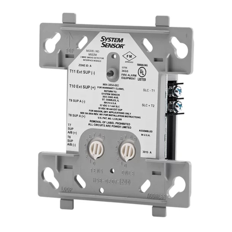
M502M Two-wire Conventional
Detector Interface Module
INSTALLATION AND MAINTENANCE INSTRUCTIONS
A Division of Pittway
3825 Ohio Avenue, St. Charles, Illinois 60174
1-800-SENSOR2, FAX: 630-377-6495
Before Installing
This information is included as a quick reference installa-
tion guide. Refer to the appropriate installation manual for
detailed system information. If the modules will be in-
stalled in an existing operational system, inform the opera-
tor and local authority that the system will be temporarily
out of service. Disconnect power to the control panel before
installing the modules.
NOTICE: This manual should be left with the owner/user
of this equipment.
General Description
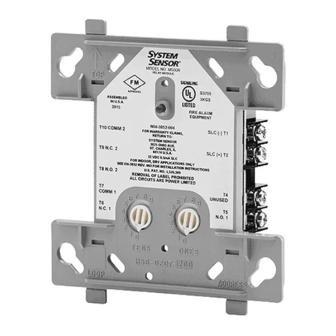
The M502M Interface Module allows intelligent panels to
interface and monitor two-wire conventional smoke detec-
Specifications
Temperature: 32°to 120°F (0°to 49°C)
Humidity: 10% to 93% Noncondensing
Weight: .5 lbs (232 g)
Dimensions: 41/2"H, 4"W, 11/4"D (Mounts to 4"square by 21/8"deep electrical boxes.)
Test Features: Magnetically activated reed switch.
Accessories: SMB500 Surface Mount Box for 500 series modules
M02-04-00 Test Magnet for testing devices
Communication Line – Terminals 1 & 2
Voltage: 15 – 32 VDC
Current: 200
µ
A Max @ 24 VDC, no communication
1.3 mA Max (Style D enabled)
5.1 mA Max 24V (LED latched on)
Loop Impedance: 40 ΩMax
External Power Supply Requirements – Terminals 3 & 4
Voltage: 17.6 – 28.2 VDC (filtered, regulated, and power-limited)
Ripple: 100mV RMS Max
Current: 92 mA per module
(Power must be interrupted to reset detectors. The interface module must have a minimum of 15 VDC at terminals 3 and 4
to function properly. Ground fault detection must be accomplished by the control panel.)
Initiating Device Circuit (IDC) – Terminals 6, 7, 8, & 9
Voltage: 12.5 to 30.3 VDC (Ripple: 100mV RMS Max)
Current: 92 mA Max
IDC Loop Impedance: 25 ΩMax
Standby Current: 10 mA Max @ maximum IDC voltage
Detector Current in Standby: Up to 2.4 mA
Alarm Current: 20 mA minimum
Style: Style B (class B) / Style D (class A)
EOL Resistance: 3.9K ohm nominal
(Detector loop current is sufficient to ensure operation of one alarmed detector per zone.)
tors. All two-wire detectors being monitored must be UL
compatible with the module.
The module is addressed through the communication line
of intelligent systems. When the module is interrogated, it
transmits the status of one zone of two-wire detectors to an
intelligent control panel. Status conditions are reported as
normal, open, or alarm. The interface module supervises
the zone of detectors and the connection of an external
power supply.
Two rotary decade switches allow setting module addresses
from 00–99. A status LED indicator is provided and is con-
trolled by code command from the control panel. The mod-
ule provides a magnetically activated test switch for testing
Technical Manuals Online! - http://www.tech-man.com
D500-19-00 2 I56-762-01
Compatible Two-wire System Sensor Smoke Detectors for Use with M502M with Zone Identifier A:
Detector Compatability Detector Base Base Max
Model ID Type Model Identifier Detectors
1451 A Ionization B401/B A 20
2451 A Photoelectric B401/B A 20
2451TH A Photoelectric with Thermal B401/B A 20
1400 A Ionization N/A — 20
2400 A Photoelectric N/A — 20
2400TH A Photoelectric with Thermal N/A — 20
1100 A Ionization N/A —20
1151 A Ionization B110LP/B401 A 20
2100 A Photoelectric N/A — 20
2100T A Photoelectric with Thermal N/A — 20
2151 A Photoelectric B110LP/B401 A 20
Figure 1. Module controls and indicators:
ISOLATED
QUADRANT
Figure 2B:
A78-2611-00
the module’s electronics and connections to the control
panel (see Figure 1).
Compatibility Requirements
To insure proper operation, this module shall be connected
to compatible intelligent control panels only.Conventional
two-wire smoke detectors must be UL compatible with the
interface module. A list of compatible two-wire convention-
al detectors is below.
Package Contents
The interface module includes the following items:
(1) Two-wire interface module
(1) 3.9K ohm end-of-line resistor (A2143-10)
(1) Off-white cover plate
(1) Screw pack for cover plate
Mounting
The M502M Interface Module mounts directly to 4 inch
square electrical boxes as shown in Figure 2. The box must
have a minimum depth of 2-1/8 inches.
Wiring
NOTE: All wiring must conform to applicable local codes,
ordinances and regulations. When using control
modules in nonpower limited applications, the Sys-
tem Sensor CB500 Module Barrier must be used to
meet UL requirements for the separation of power-
limited and nonpower-limited terminals and wir-
ing. The barrier must be inserted in a 4"x4"x21 /8"
junction box, and the control module must be
placed into the barrier and attached to the junction
box (Figure 2A). The power-limited wiring must be
placed into the isolated quadrant of the module
barrier (Figure 2B).
1. Install module wiring in accordance with the job draw-
ings and appropriate wiring diagrams (Figures 3 – 5).
2. Set the address on the module per job drawings.
3. Secure module to electrical box (supplied by installer),
as shown in Figure 2A.
Testing
The M502M Interface Module can be tested with a test
magnet available from System Sensor (M02-04-01- see Fig-
ure 1). The magnet test checks the module’s electronics
and connections to the control panel. Interfaced two-wire
detectors must be tested independently. Test two-wire de-
tectors per manufacturer’s installation instructions.
STATUS LED
ROTARY DECADE
ADDRESS SWITCHES
MAGNET TEST
POSITION
27
0
1
3456
8
9
27
0
1
3456
8
9
A78-2318-00
A78-2610-00
Figure 2A. Mounting module with barrier:
Technical Manuals Online! - http://www.tech-man.com
D500-19-00 3 I56-762-01
A78-2394-06
Figure 4. Interface two-wire conventional detectors, NFPA Style D:
A78-2395-07
Figure 3. Interface two-wire conventional detectors, NFPA Style B:
1 (–)
2 (+)
MODULE
(+)
(–) (–) 9
(+) 8
(+) 7
(–) 6
INTERFACE
FROM PANEL OR (+)
(–)
CONNECT MODULES TO LISTED
COMPATIBLE CONTROL
PANELS ONLY.
32 VDC MAX.
TWISTED PAIR
IS RECOMMENDED
TO NEXT
(+)
(–)
DEVICE
LISTED BATTERY-BACKUP, SWITCHED
DC POWER SUPPLY.
SEE REQUIREMENTS ON PAGE 3.
DO NOT LOOP WIRE UNDER TERMINALS. BREAK WIRE
RUN TO PROVIDE SUPERVISION OF CONNECTIONS.
INSTALL DETECTORS PER MANUFACTURER'S
INSTALLATION INSTRUCTIONS.
POWER TO THE INTERFACE MODULE
MUST BE EXTERNALLY SWITCHED TO
CONTROL MODULE CAN BE USED TO
SWITCH POWER FROM A STANDARD
DETECTORS MUST BE UL LISTED COMPATIBLE WITH MODULE.
+
–
+
–
OPTIONAL BRANCH CIRCUIT
(–)
(+)
3 (–)
4 (+)
5
POWER SUPPLY - SEE FIGURE 5.
PREVIOUS DEVICE
RESET THE DETECTORS. A TC810A
TO NEXT INTERFACE MODULE.
MODULE SUPERVISES SUPPLY
VOLTAGE AND DETECTOR LOOP.
COMMUNICATION LINE
IDC INSTALLATION WIRING MUST NOT EXCEED
DO NOT MIX FIRE ALARM INITIATING, SUPERVISORY,
OR SECURITY DEVICES ON THE SAME MODULE.
2-WIRE CONVENTIONAL DETECTOR
INITIATING DEVICE CIRCUIT (IDC) - NFPA STYLE D
POWER LIMITED: 92ma MAX; 30.3 VDC MAX
25 OHMS, 12 - 18 AWG.
3.9K EOL RESISTOR
REQUIRED AT TERMINALS
8 & 9 (INCLUDED)
TERMINAL WIRING MUST BE POWER LIMITED.
1 (–)
2 (+)
MODULE
(+)
(–)
(–) 9
(+) 8
(+) 7
(–) 6
INTERFACE
FROM PANEL OR
(+)
(–)
CONNECT MODULES TO LISTED
COMPATIBLE CONTROL
PANELS ONLY. 32 VDC MAX.
TWISTED PAIR
IS RECOMMENDED
TO NEXT
(+)
(–)
DEVICE
LISTED BATTERY-BACKUP SWITCHED
DC POWER SUPPLY.
SEE REQUIREMENTS ON PAGE 3.
DO NOT LOOP WIRE UNDER TERMINALS. BREAK WIRE
RUN TO PROVIDE SUPERVISION OF CONNECTIONS.
INSTALL DETECTORS PER MANUFACTURER'S
INSTALLATION INSTRUCTIONS.
IDC INSTALLATION WIRING MUST NOT EXCEED
DO NOT MIX FIRE ALARM INITIATING, SUPERVISORY,
OR SECURITY DEVICES ON THE SAME MODULE.
POWER TO THE INTERFACE MODULE
MUST BE EXTERNALLY SWITCHED TO
CONTROL MODULE CAN BE USED TO
SWITCH POWER FROM A STANDARD
OPTIONAL BRANCH CIRCUIT
2-WIRE CONVENTIONAL DETECTOR
DETECTORS MUST BE UL LISTED COMPATIBLE WITH MODULE.
+
–
+
–
RESISTOR
(INCLUDED)
INITIATING DEVICE CIRCUIT (IDC) - NFPA STYLE B
3 (–)
4 (+)
(–)
(+)
5
POWER SUPPLY - SEE FIGURE 5.
PREVIOUS DEVICE
RESET THE DETECTORS. A TC810A
TO NEXT INTERFACE MODULE.
MODULE SUPERVISES SUPPLY
VOLTAGE AND DETECTOR LOOP.
COMMUNICATION LINE
POWER LIMITED: 92ma MAX; 30.3 VDC MAX
25 OHMS, 12 - 18 AWG.
3.9K EOL
TERMINAL WIRING MUST BE POWER LIMITED.
M502M Interface Module Wiring Diagrams
Technical Manuals Online! - http://www.tech-man.com
D500-19-00 4 I56-762-01
© System Sensor 1996
Three-Year Limited Warranty
System Sensor warrants its enclosed module to be free from defects in ma-
terials and workmanship under normal use and service for a period of
three years from date of manufacture. System Sensor makes no other ex-
press warranty for this module. No agent, representative, dealer, or em-
ployee of the Company has the authority to increase or alter the
obligations or limitations of this Warranty. The Company’s obligation of
this Warranty shall be limited to the repair or replacement of any part of
the module which is found to be defective in materials or workmanship
under normal use and service during the three year period commencing
with the date of manufacture. After phoning System Sensor’s toll free
number 800-SENSOR2 (736-7672) for a Return Authorization number,
send defective units postage prepaid to: System Sensor, Repair Depart-
ment, RA #__________, 3825 Ohio Avenue, St. Charles, IL 60174. Please
include a note describing the malfunction and suspected cause of failure.
The Company shall not be obligated to repair or replace units which are
found to be defective because of damage, unreasonable use, modifica-
tions, or alterations occurring after the date of manufacture. In no case
shall the Company be liable for any consequential or incidental damages
for breach of this or any other Warranty, expressed or implied whatsoever,
even if the loss or damage is caused by the Company’s negligence or fault.
Some states do not allow the exclusion or limitation of incidental or conse-
quential damages, so the above limitation or exclusion may not apply to
you. This Warranty gives you specific legal rights, and you may also have
other rights which vary from state to state.
A78-2396-06
1 (–)
2 (+)
MODULE
(+)
(–)
CONTROL
9
8
7
6
5
3
4
J1 & J2
BREAK TABS J1 & J2
TO ENABLE FORM 'C' MODE
RELAY CONTACT RATINGS:
RESISTIVE:
INDUCTIVE:
PILOT DUTY:
2 A @ 30 VDC
1 A @ 30 VDC (.6 PF)
.6 A @ 30 VDC (.35 PF)
.3 A @ 110 VDC (.35 PF)
.3 A @ 120 VAC (.35 PF)
FROM PANEL OR
(+)
(–)
SEE REQUIREMENTS ON PAGE 3
DC POWER SUPPLY, LISTED FOR FIRE
PROTECTION WITH BATTERY BACKUP
(+)
(–)
(MONITOR LOSS OF INPUT POWER)
CONTACTS ARE SHOWN IN STANDBY.
CONTACTS MAY HAVE SHIFTED TO ALARM
TO NEXT
(+)
(–)
DEVICE
CONNECT MODULES TO LISTED
COMPATIBLE CONTROL
PANELS ONLY. TWISTED PAIR
IS RECOMMENDED
(+)
(–)
DURING SHIPPING. DO NOT APPLY
POWER TO THE CIRCUITS THE MODULE
PREVIOUS DEVICE
SWITCHED RISER
CIRCUIT FOR
INTERFACE MODULES
TC810A CONTROL
MODULE IS NOT REQUIRED
IF SWITCHABLE POWER
IS AVAILABLE.
COMMUNICATION LINE
CONTROLS UNTIL THE MODULE IS
CONNECTED TO AND ACCEPTED BY THE PANEL.
32 VDC MAX.
TERMINAL WIRING MUST BE POWER LIMITED.
Figure 5. M500C series control module switching a power supply (controls switched 24 VDC external power
to M502M)
Technical Manuals Online! - http://www.tech-man.com

Other System Sensor Control Unit manuals
System Sensor EM-1SRI User manual

System Sensor

System Sensor EM-1SRI User manual

System Sensor i3 Series User manual

System Sensor

System Sensor i3 Series User manual

System Sensor M210EA-CZR User manual

System Sensor

System Sensor M210EA-CZR User manual

System Sensor RR2 User manual

System Sensor

System Sensor RR2 User manual

System Sensor M500M User manual

System Sensor

System Sensor M500M User manual

System Sensor M500FP User manual

System Sensor

System Sensor M500FP User manual

System Sensor M210E User manual

System Sensor

System Sensor M210E User manual

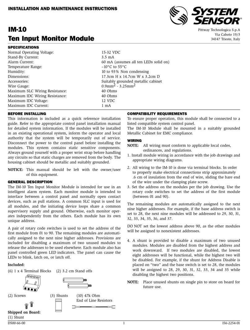
System Sensor IM-10 User manual

System Sensor

System Sensor IM-10 User manual

System Sensor M500M User manual

System Sensor

System Sensor M500M User manual

System Sensor RR1 User manual

System Sensor

System Sensor RR1 User manual

System Sensor M502M User manual

System Sensor

System Sensor M502M User manual

System Sensor MDl Series User manual

System Sensor

System Sensor MDl Series User manual

System Sensor M500FP User manual

System Sensor

System Sensor M500FP User manual

System Sensor 500 Series User manual

System Sensor

System Sensor 500 Series User manual

System Sensor MOD400R User manual

System Sensor

System Sensor MOD400R User manual

System Sensor IM-10 User manual

System Sensor

System Sensor IM-10 User manual

System Sensor SC-6 User manual

System Sensor

System Sensor SC-6 User manual

System Sensor CR-6 Instruction Manual

System Sensor

System Sensor CR-6 Instruction Manual

System Sensor Supervised Control Module M500S User manual

System Sensor

System Sensor Supervised Control Module M500S User manual

System Sensor I4 Series User manual

System Sensor

System Sensor I4 Series User manual

System Sensor MDL3 Series User manual

System Sensor

System Sensor MDL3 Series User manual

System Sensor EM-1MI User manual

System Sensor

System Sensor EM-1MI User manual
System Sensor SC-6 User manual

System Sensor

System Sensor SC-6 User manual

System Sensor MDL3W User manual

System Sensor

System Sensor MDL3W User manual
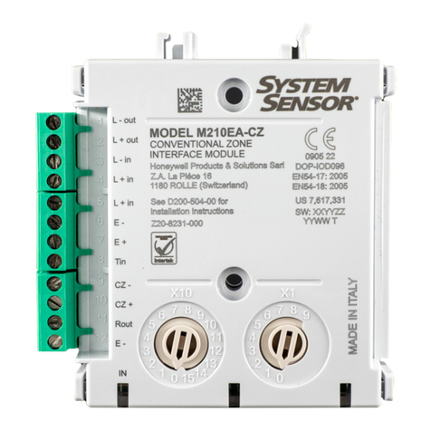
Popular Control Unit manuals by other brands

DNP Wireless Connect Module quick start guide

DNP

DNP Wireless Connect Module quick start guide

ITRON 8600 Series instruction manual

ITRON

ITRON 8600 Series instruction manual

Spectrum Controls 1794sc-IRT8I user manual

Spectrum Controls

Spectrum Controls 1794sc-IRT8I user manual

Niles TVC-1 Installation & operation guide

Niles

Niles TVC-1 Installation & operation guide

Modtech PCCU-100 Operator's manual

Modtech

Modtech PCCU-100 Operator's manual

Keysight Technologies M9170A Configuration guide

Keysight Technologies

Keysight Technologies M9170A Configuration guide

CALEFFI MixCal 521410A Installation and commissioning manual

CALEFFI

CALEFFI MixCal 521410A Installation and commissioning manual

BVA Hydraulics PUW2 instruction manual

BVA Hydraulics

BVA Hydraulics PUW2 instruction manual

Graco Gun Flush Box 570046 Instructions-parts list

Graco

Graco Gun Flush Box 570046 Instructions-parts list

Zodiac PRO user manual

Zodiac

Zodiac PRO user manual

VTS Medical Systems ventus VS 10-75 CG UPC Operation and maintenance manual

VTS Medical Systems

VTS Medical Systems ventus VS 10-75 CG UPC Operation and maintenance manual

ASA Hydraulik SDA Series manual

ASA Hydraulik

ASA Hydraulik SDA Series manual

SOMFY P.TILT RTS M+L instructions

SOMFY

SOMFY P.TILT RTS M+L instructions

bolid S2000-SP4/220 instruction manual

bolid

bolid S2000-SP4/220 instruction manual

Bristan PM2 SHC3DIV C Installation instructions and user guide

Bristan

Bristan PM2 SHC3DIV C Installation instructions and user guide

CALEFFI 521201 Installation and commissioning manual

CALEFFI

CALEFFI 521201 Installation and commissioning manual

Kessel Comfort PLUS original operation manual

Kessel

Kessel Comfort PLUS original operation manual

HEIDENHAIN ITNC 530 - CONVERSATIONAL PROGRAMMING user manual

HEIDENHAIN

HEIDENHAIN ITNC 530 - CONVERSATIONAL PROGRAMMING user manual

manuals.online logo
manuals.online logoBrands
  • About & Mission
  • Contact us
  • Privacy Policy
  • Terms and Conditions

Copyright 2025 Manuals.Online. All Rights Reserved.