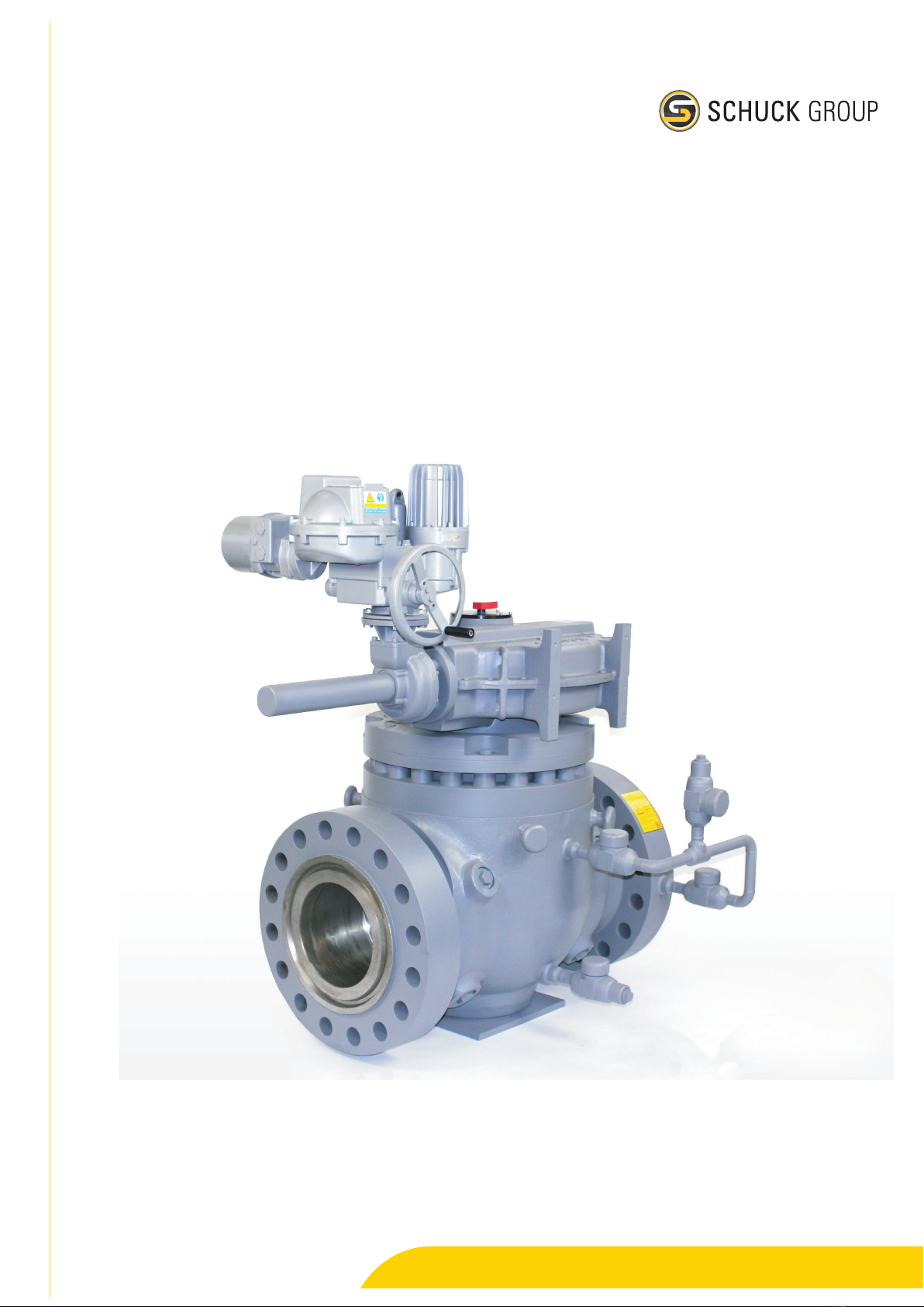
SCHUCK U User manual

Franz Schuck GmbH
Installation/operation manual
Type U ball valve
Translation of the original Operation Manual
Keep for future use!
avrora-arm.ru
+7 (495) 956-62-18

Introduction
This manual is written for installation, operating, maintenance and supervisory
personnel.
This manual also describes components and auxiliary units that are not included
or are only partially included in the scope of supply.
The manual must be read, understood and observed by the user. We emphasize
that Franz Schuck GmbH assumes no liability for damage or malfunctions arising
from non-compliance with this manual.
With regard to the illustrations and information in this manual, we reserve the right
to make technical modifications.
Copyright
The copyright for this manual remains with Franz Schuck GmbH.
The instructions and drawings contained herein may not be reproduced or dissem-
inated either fully or in part, nor used for competitive purposes or communicated
to other parties without authorization.

2013-02-09 I
Table of Contents
Table of Contents
Chapter 1 1-1Preliminary remarks
1.1 1-1Legal notes
1.2 1-1Application range
Chapter 2 2-1Safety
2.1 2-1Fundamental safety instructions
2.1.1 2-1General
2.1.2 2-3Intended use
2.1.3 2-4Organizational measures
2.1.3.1 2-4Special hazard points
2.1.3.2 2-5Workplace and personal protective gear
Chapter 3 3-1Description
3.1 3-1System overview
3.1.1 3-3Identification plate
3.1.2 3-4Construction and design
3.1.3 3-4Sealing off the outlet
3.1.4 3-4Sealing out the atmosphere
3.1.5 3-4Actuating stem
3.1.6 3-5Actuation
3.1.7 3-5Accessories and connections
Chapter 4 4-1Assembly
4.1 4-3Preparation
4.1.1 4-3As-delivered condition
4.1.2 4-4Inspection
4.1.3 4-4Storage
4.1.4 4-4Transport
4.2 4-6Installation
4.2.1 4-6General installation instructions
4.2.2 4-7Ball valves with weld ends
4.2.3 4-8Ball valves with flanges

2013-02-09 II
Table of Contents
4.2.4 4-9Valve installation
4.2.5 4-9Connection and start-up of actuator and control system
4.3 4-10Testing
4.3.1 4-10Function test
4.3.2 4-10Pressure/leak tightness test
Chapter 5 5-1Operation
5.1 5-1Safety instructions for operation
5.2 5-2Operation
5.2.1 5-2Open/close valve
Chapter 6 6-1Maintenance
6.1 6-2Inspection
6.1.1 6-2Regular maintenance
6.1.2 6-2Venting/drain
6.1.3 6-3Double block and bleed test
6.1.4 6-3Injecting sealant (optional)
6.1.4.1 6-3Internal leaks on seat rings
6.1.4.2 6-4Sealing the actuating stem
6.1.4.3 6-4Sealing the bonnet sealing
6.1.5 6-5Faults and troubleshooting
6.1.6 6-5Inspection intervals
6.2 6-6Repairs
Chapter 7 7-1Appendix
7.1 7-1Tightening sequence for flange bolts
7.2 7-2Conversion factors
7.3 7-3Calculation formula to determine the carbon equivalent (CEV)
7.3.1 7-3Calculation formula (standard)
7.3.2 7-3Calculation formula for steels with different consistencies
7.4 7-4Sealant requirement per ball valve (above ground)

Type U ball valve
2013-02-09 1-1
Codeword: XML Source: 100: Kugelhahn
Created with: TeXML v.schuck-latex-130207
Author: Franz Schuck GmbH
Editor: bitplant.de GmbH
As of: 2013-01-07
Revision: 2013/01
Preliminary remarks
1 Preliminary remarks
CAUTION
Danger of consequential damage due to incorrect operation, maintenance and/
or handling!
We explicitly emphasize that we assume no liability for damage or malfunctions
arising from non-compliance with this manual.
ÖTherefore it is important to comply with all instructions in this manual!
This manual is to provide technicians and users with the necessary information
for assembly and adjustment work and to help in performing work quickly and
correctly.
For your own safety, read this manual carefully and pay particular attention to the
highlighted tips. In any case, keep this manual to hand.
Pay special attention to all safety instructions in this manual. You will find the
safety instructions in Chapter 2, in the introductions to chapters and before prac-
tical instructions. The General Terms and Conditions of the company apply exclu-
sively to all deliveries and performances made by Franz Schuck GmbH, including
any future transactions.
1.1 Legal notes
The component may only be installed and operated by skilled personnel.
Please check parts upon receipt for any possible damage that may have occurred
during transport. Only undamaged parts may be fitted or used.
No warranty can be claimed if maintenance work is neglected or carried out incor-
rectly. Only original spare parts guarantee quality, reliability and exchangeability.
Any modification(s) of the component are in general prohibited by Franz Schuck
GmbH. The manufacturer guarantee becomes void if this prohibition is not com-
plied with!
1.2 Application range
This operation manual applies to the Franz Schuck GmbH product described in this
manual.
The appropriate operation manuals for optional accessories must also be ob-
served.
These operation manuals are included in the overall documentation if the acces-
sories belong to the scope of supply from Franz Schuck GmbH.

Type U ball valve
2013-02-09 2-1
Codeword: XML Source: 100: Kugelhahn
Created with: TeXML v.schuck-latex-130207
Author: Franz Schuck GmbH
Editor: bitplant.de GmbH
As of: 2013-01-07
Revision: 2013/01
Safety
2 Safety
CAUTION
Dangers to the health and safety of operating and maintenance staff as well
as to the functioning capacity of the valve. Dangers to the environment due to
escaping gaseous or liquid media.
Escaping sour gas or sulphinic lye might cause life danger hazard!
Non-compliance with these instructions jeopardizes the obligation by Franz
Schuck GmbH to follow through on the warranty/guarantee.
ÖThe instructions in the “Safety”Chapter must be unconditionally observed!
2.1 Fundamental safety instructions
2.1.1 General
Modifications on valves and attachments which could affect safety may not be
carried out without written permission from the manufacturer.
The guarantee becomes void if this prohibition is not complied with!
i
•This product has been manufactured according to the recognized rules of
technology and according to internal Schuck quality standards; the product is
shipped from the factory in a perfect technical condition
•Nevertheless, valves can cause hazards to people, material goods and the en-
vironment if operating personnel use them improperly or in a manner that is
contrary to their intended use
•Any person dealing with assembly, commissioning, operation and/or mainte-
nance of the valve must have read and understand this entire manual, and must
be able to prove they possess professional qualifications for implementing the
work
•Please observe the valid accident prevention regulations when installing the
component
•Suitable protective gear must be worn when carrying out the works
•The manual must be kept safe and accessible at all times at the place where
the valve is in use
•If malfunctions occur, notify Franz Schuck GmbH immediately and take appro-
priate measures
•Work on ball valves (such as inspection, servicing and/or maintenance work)
may only be carried out in a depressurized state and with the energy supply
secured and switched off

Type U ball valve
2013-02-09 2-2
Codeword: XML Source: 100: Kugelhahn
Created with: TeXML v.schuck-latex-130207
Author: Franz Schuck GmbH
Editor: bitplant.de GmbH
As of: 2013-01-07
Revision: 2013/01
Safety / Fundamental safety instructions
•Valves must be effectively covered and/or protected when work is being carried
out that could lead to contamination or damage to the valve, the assembled
parts and/or the anti-corrosion protection

Type U ball valve
2013-02-09 2-3
Codeword: XML Source: 100: Kugelhahn
Created with: TeXML v.schuck-latex-130207
Author: Franz Schuck GmbH
Editor: bitplant.de GmbH
As of: 2013-01-07
Revision: 2013/01
Safety / Fundamental safety instructions
2.1.2 Intended use
The ball valve supplied is designed exclusively to allow or block the flow of media
in pipelines.
Depending on the sealing system, the ball valve can be used both for gaseous and
liquid media.
Any other media and/or applications outside the permissible pressure and temper-
ature range can lead to damage and/or leaks.
Intended use includes observing the instructions in this operating manual and ad-
hering to the operating conditions on the identification plate, the final inspection
certification and drawings, as well as observing the locally applicable accident pre-
vention guidelines and regulations for protecting the environment.
Any operating conditions or applications which differ from those prescribed are
only valid with the agreement of Franz Schuck GmbH!

Type U ball valve
2013-02-09 2-4
Codeword: XML Source: 100: Kugelhahn
Created with: TeXML v.schuck-latex-130207
Author: Franz Schuck GmbH
Editor: bitplant.de GmbH
As of: 2013-01-07
Revision: 2013/01
Safety / Fundamental safety instructions
2.1.3 Organizational measures
2.1.3.1 Special hazard points
There is no immediate danger from a valve that is installed and serviced according
to instructions.
•Danger from escaping media
–depending on the working medium, fire or explosion hazards can arise from
electrical contact, naked flames, light and/or smoking
–there is a risk of poisoning, chemical burns, scolding and environmental
pollution
–hazardous materials must be collected or sucked up, if necessary, and dis-
posed of properly
•The voltage in electrically operated ball valves poses a potential danger
–all work on electrical installations may only be carried out by trained elec-
tricians and only at zero potential
•Stored energy is an imminent danger in the case of ball valves that are actuated
pneumatically, hydraulically or gas-hydraulically
–all energy-storing systems must be depressurized during servicing and
maintenance works
–Work on the ball valve may only be carried out in a depressurized state. This
also applies for the disassembly of caps and screw connections as well as
adjustment works on the ball valve.

Type U ball valve
2013-02-09 2-5
Codeword: XML Source: 100: Kugelhahn
Created with: TeXML v.schuck-latex-130207
Author: Franz Schuck GmbH
Editor: bitplant.de GmbH
As of: 2013-01-07
Revision: 2013/01
Safety / Fundamental safety instructions
2.1.3.2 Workplace and personal protective gear
Sufficient space is required for carrying out assembly and maintenance work
safely. The operator must ensure that the workplace is clean and clearly arranged.
If media (including residues) can escape in case the ball valve or the actuator sys-
tem experiences operational faults or malfunctions, then the endangered persons
must use suitable personal protective gear, as far as this is necessary.
Only use components in a technically perfect condition; use them according to
specifications in a safety and risk-conscious manner while complying with the op-
eration manual! Remedy faults in particular that could impair safety (or have them
remedied)!
The operating manual must be supplemented by instructions which take into ac-
count supervisory and reporting duties with regard to work related particularities,
e.g. in respect of how work is organized, working procedures and the personnel
employed.
Technically trained staff commissioned to work on a component must have read
the chapter on safety in this operating manual before starting work. Staff must
already be aware of potential hazard sources when working to be in a position to
react quickly and correctly. This applies in particular to staff who are only employed
occasionally to work on a component, e.g. when setting up or servicing.
Observe all safety and hazard instructions for the equipment/the component!
Make sure all safety and hazard signs are complete and legible!
No modifications, attachments or conversions which could impair safety may be
implemented without authorization from Franz Schuck GmbH! This also applies to
the assembly and the adjustment of safety devices and safety valves as well as for
welding on load-bearing parts.
Lubricants and sealing compounds as well as spare parts should conform to the
technical specifications. This is always guaranteed when using original spare
parts.
Replace hydraulic and pneumatic hose lines in specified or appropriate intervals,
even if no security-relevant defects are evident.
Adhere to the prescribed deadlines, or the deadlines stated in the operation man-
ual, for recurring tests/inspections!
Appropriate workshop equipment is essential for carrying out maintenance work.
Make sure the location or fire extinguishers is clearly indicated and operating in-
structions are available!
Make sure to observe the fire alarm and fire fighting instructions!
DANGER
Risk of injury from bursting components/system parts!
If the permissible limit values are exceeded, the
component/system can be destroyed, and as a
consequence of this persons can be injured or killed!
ÖAlways operate components/system parts within the
permissible limit values!

Type U ball valve
2013-02-09 3-1
Codeword: XML Source: 100: Kugelhahn
Created with: TeXML v.schuck-latex-130207
Author: Franz Schuck GmbH
Editor: bitplant.de GmbH
As of: 2013-01-07
Revision: 2013/01
Description
3 Description
3.1 System overview
Task
Depending on the design, the ball valve is used as shut-off device in pipelines for
the transport of gaseous or liquid media.
Components of the version with weld ends
1
2
3120nn106
Fig. 3-1 System overview type U ball valve
1Actuating stem
2Vent connection (optional)
3Drainage (optional)

Type U ball valve
2013-02-09 3-2
Codeword: XML Source: 100: Kugelhahn
Created with: TeXML v.schuck-latex-130207
Author: Franz Schuck GmbH
Editor: bitplant.de GmbH
As of: 2013-01-07
Revision: 2013/01
Description / System overview
Components of the version with flanges
1 2 3 4
5
67
120nn111
Fig. 3-2 System overview type U ball valve
1Actuating stem
2Injection head for secondary sealant for
the bonnet sealing (optional)
3Injection head for secondary sealant on
actuating stem (optional)
4Vent connection (optional)
5Injection head for secondary sealant on
the seat (optional)
6Drainage (optional)
7Injection head for secondary sealant on
the seat (optional)
Function
Rotating the ball plug by 90° achieves the “OPEN”or “CLOSED”position of the ball
valve, i.e. the entire cross sectional area of the ball outlet is released or blocked
for the passage of the delivery flow.

Type U ball valve
2013-02-09 3-3
Codeword: XML Source: 100: Kugelhahn
Created with: TeXML v.schuck-latex-130207
Author: Franz Schuck GmbH
Editor: bitplant.de GmbH
As of: 2013-01-07
Revision: 2013/01
Description / System overview
3.1.1 Identification plate
For valves specified for above ground installation, the identification plate is at-
tached to the housing body; on the underground model, it is also optionally posi-
tioned in the upper area of the pipe or extension.
Components
SCHUCK
Franz Schuck GmbH
Daimlerstraße 4—7
D — 89555 Steinheim
Kugelhahn — Ball Valve
Typ / Type PN / CL Ident-Nr. / Ident. nº.
DN / NPS
Max. press. at min. temp.
Gehäuse Material / Body material
TAG-Nr. / Tag nº. Herstelljahr / Year built Gewicht / Weight
Einbauten / Trim identification Auftrags-Nr. / W.o. nº.
Max. press. at max. temp. PT / Test pressure
Baulänge / Face to face dim.
15
15
5
6
12
12
8
3 4
10
10
13
13
9
7
16
16
17
17
14
14
[mm / inch] [mm]
[bar/°C] [bar/°C] [bar]
Pos.
6D-0279-6FA
1 2
11
11
110nn009
Fig. 3-3 Information on the identification plate
1CE/API mark
2Space for acceptance reference
by an expert
3Type
4Nominal pressure PN/ANSI class
5Ident no.
6Nominal diameter DN/NPS
7Face-to-face dimension
8Max. permissible operating pressure PS
at minimum temperature
9Max. permissible operating pressure PS
at maximum temperature
10 Test pressure PT
11 Body material
12 Reference for built-in structures
13 Order no.
14 Order position
15 TAG no. (optional)
16 Year built
17 Weight

Type U ball valve
2013-02-09 3-4
Codeword: XML Source: 100: Kugelhahn
Created with: TeXML v.schuck-latex-130207
Author: Franz Schuck GmbH
Editor: bitplant.de GmbH
As of: 2013-01-07
Revision: 2013/01
Description / System overview
3.1.2 Construction and design
The U type ball valve is a top entry construction.
The ball plugs are mounted in the casing and in the cover.
Type U ball valves are available with weld ends for welding into the pipe or with
flange ends.
Ball valves with complete bores have a smooth, circular outlet without constriction
and pigs whose dimensions and design do not compromise the functioning of the
ball valve can be passed through them
With reduced valves or Venturi models, only the connecting pieces are developed
in a tapered from as a junction to the larger pipeline. Piggability is possible only
to a very limited extent with special pigs and after consultation.
The structural lengths of the ball valves are stipulated according to API –6D or EN
558 –1 depending on nominal diameter and pressure ranges. Special structural
lengths are possible on request.
3.1.3 Sealing off the outlet
The outlet is sealed by two seat rings positioned on opposite sides in contact with
the ball.
Depending to the requirements, the sealing system can be designed to be soft-
seated, PMSS (primary metallic, secondary soft seated) or just metal-to-metal.
For gaseous media, seat rings with a double piston effect are usually used; for
liquid media, seat rings with a single piston effect are used. Combinations are
also possible.
In the case of U type ball valves it is possible to retrofit/replace the seat rings or
the sealing system.
3.1.4 Sealing out the atmosphere
The actuating stem is double-sealed against the atmosphere in the cover. The first
seal is a special grooved ring. O-rings are installed as second seal.
Additionally, a fire safe sealing package with a graphite ring is usually installed. If
necessary, the sealing package can be replaced.
In principle, repair work may only be carried out by the Franz Schuck GmbH service
team or by personnel trained by Franz Schuck.
i
3.1.5 Actuating stem
The actuating stem transfers the quarter rotation for opening and closing.
It is not possible to release the actuator stem from the housing during operation
(blow out protection).

Type U ball valve
2013-02-09 3-5
Codeword: XML Source: 100: Kugelhahn
Created with: TeXML v.schuck-latex-130207
Author: Franz Schuck GmbH
Editor: bitplant.de GmbH
As of: 2013-01-07
Revision: 2013/01
Description / System overview
3.1.6 Actuation
Depending on the order, the ball valve can either be supplied with manual actu-
ation (hand wheel or hand lever) or with an electrical/pneumatic/hydraulic valve
actuator.
The ball valve is usually opened by an anticlockwise 90° rotation on the actuating
stem. It is closed by clockwise rotation.
The ball valve has no internal stops to limit the rotation angle. The rotation angle
is limited by adjustable limit stops in the drive.
Please observe the operating manuals for actuator and control system (acces-
sories).
3.1.7 Accessories and connections
Depending on the order, the ball valve can be equipped from the factory with op-
tional accessories or with interfaces for other accessories (ÎPage 3-1, Fig. 3-1):
•Drainage
•Ventilation
•Injection heads for secondary sealant
•Pressure supply for gas-over-oil actuator system
•Pressure gauge connection
•Hydraulic seat ring pressing

Type U ball valve
2013-02-09 4-1
Codeword: XML Source: 100: Kugelhahn
Created with: TeXML v.schuck-latex-130207
Author: Franz Schuck GmbH
Editor: bitplant.de GmbH
As of: 2013-01-07
Revision: 2013/01
Assembly
4 Assembly
For questions regarding assembly, please contact:
Franz Schuck GmbH
Daimlerstraße 5 –7
89555 Steinheim
GERMANY
Phone +49 (7329) 950-0
Fax +49 (7329) 950-161
www.schuck-group.com
DANGER
Risk of injury from bursting components/system parts!
If the permissible limit values are exceeded, the
component/system can be destroyed, and as a
consequence of this persons can be injured or killed!
ÖAlways operate components/system parts within the
permissible limit values!
DANGER
Risk of injury from bursting components/system parts!
Only carry out installation work when the valve is depres-
surized!
The on-site instructions of the operator must be addition-
ally observed.
ÖEnsure that the system is depressurized and that no
gas is present in the environment before starting
installation work.
ÖBlock the gas flow as specified by the operating
company.
ÖOpen the venting and discharge opening and secure
mechanically against closing.

Type U ball valve
2013-02-09 4-2
Codeword: XML Source: 100: Kugelhahn
Created with: TeXML v.schuck-latex-130207
Author: Franz Schuck GmbH
Editor: bitplant.de GmbH
As of: 2013-01-07
Revision: 2013/01
Assembly
DANGER
Danger of electric shock!
ÖDo not connect the system to power before the earth
resistance and the earthing connection has been
tested, examined and approved by the customer.
CAUTION
Danger of hardness increase of the steel when welding without pre-heating the
weld junction at temperatures exceeding 80 °C!
ÖPre-heat the weld-on ends depending on the carbon equivalent (CEV) before
starting the welding process.
ÖObserve the instructions concerning the CEV (ÎPage 7-3, Chapter 7.3).
ÖMake sure to monitor the temperature when pre-heating and welding!
Suitable measures (such as cooling, extending the weld-on ends without
coating, dismantling, etc.) must be taken to avoid elevated temperatures in
areas with coated surfaces.
Temperatures of up to 100 °C are permissible for a short time.

Type U ball valve
2013-02-09 4-3
Codeword: XML Source: 100: Kugelhahn
Created with: TeXML v.schuck-latex-130207
Author: Franz Schuck GmbH
Editor: bitplant.de GmbH
As of: 2013-01-07
Revision: 2013/01
Assembly / Preparation
4.1 Preparation
DANGER
LIFE HAZARD from suspended loads or shifting of loads!
Proceed cautiously when transporting the valve!
ÖTo lift the ball valve only use appropriate lifting devices
as well as the designated lifting points.
ÖNever hang or raise the ball valve on drive parts or
piping systems!
ÖLifting devices, industrial trucks and load-carrying
equipment and must comply with the current regula-
tions!
Notes on transport and unloading
•Load-carrying equipment according to directive 2006/42/EG (Machinery Direc-
tive)
•For the exact weight of the ball valves Îidentification plate on the ball valve
•Please observe the notes on the transport packaging ÎPage 7-5, Chapter 7.5
•Loads must be set upright or lifted according to ÎPage 4-4, Chapter 4.1.4
4.1.1 As-delivered condition
If no other contractual agreements have been made, the valves are supplied for
transport under the following conditions:
•weld-on ends and mounted flange sides are coated with an anti-corrosive prod-
uct
•the ball valve is in “OPEN”position
•valve ends are sealed with PE protective caps or wooden caps to prevent the
penetration of dirt and moisture
•the ball valves are packed on wooden pallets or boxes

Type U ball valve
2013-02-09 4-4
Codeword: XML Source: 100: Kugelhahn
Created with: TeXML v.schuck-latex-130207
Author: Franz Schuck GmbH
Editor: bitplant.de GmbH
As of: 2013-01-07
Revision: 2013/01
Assembly / Preparation
4.1.2 Inspection
Procedure
1. Check the delivery notes to make sure that the delivery is complete.
2. If there are any discrepancies, contact Franz Schuck GmbH immediately.
3. Check the delivery immediately on receipt for damage incurred during trans-
port.
In the event of damage, observe the stipulations of the insurance company
which, among other things, prescribe that evidence of damage is confirmed
immediately by the forwarding agent.
4. If applicable, photograph damage to proof evidence.
4.1.3 Storage
If possible store the valve in its original packaging.
Take suitable measures to protect the valve against external influences, dirt and
moisture.
4.1.4 Transport
Procedure
For further information ÎActuator installation/operation manual.
i
1. Only use the original packaging for transporting the valve to its place of instal-
lation.
The valve can be damaged by incorrect handling.
2. Only use lifting devices that are appropriate to the weight being moved. Please
observe the notes on the transport packaging ÎPage 7-5, Chapter 7.5.
3. Use appropriate protective materials and/or edge protectors when using steel
cables or chains in order to protect the outer coating.
4. Ensure the load does not tip sideways.
5. Loads must be set upright or lifted according to the following drawings. Never
use attachments or pipes!
6. When using suspension eyes, always use two eyes or more!
Table of contents
Popular Control Unit manuals by other brands

Albion
Albion ART 22 Flow Data and Installation Instructions

Paradox Hellas S.A.
Paradox Hellas S.A. MRTCP-IP Quick installation guide

SEMIKRON
SEMIKRON SKYPER 42 LJ R Technical Explanation

WNC
WNC M18QF Series Product user manual

ADTRAN
ADTRAN Job Aid+ 1442910G1 manual

GRAUPNER
GRAUPNER 23108 Installation and Usage

ASCO Valves
ASCO Valves 8210 Series Installation & maintenance instructions

Dixon
Dixon BAYCO 2182 Series Maintenance & Operating Instructions

Movelar
Movelar tuozi KITAWAY MODULE 84 F manual

WAREMA
WAREMA GA Kompakt Operating and installation instructions

Crystalfontz America
Crystalfontz America CFA910 user guide

Espressif Systems
Espressif Systems ESP32-S3-MINI-1 user manual