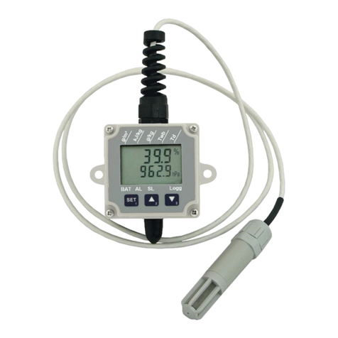
GHM Delta OHM HD33MT.4 User manual

Operating manual
Weather station data logger
HD33[L]MT.4
Keep for future reference.
www.deltaohm.com
English
Companies
/
Brands
of
GHM

HD33[L]MT.4 - 2 - V4.1
INDEX
1 INTRODUCTION .................................................................................................... 3
2 DESCRIPTION ....................................................................................................... 4
3 TECHNICAL CHARACTERISTICS ............................................................................
4 INTERNAL CONNECTIONS ..................................................................................... 8
FRONT PANEL ..................................................................................................... 11
6 CONFIGURATION MENU ...................................................................................... 12
7 SIM CARD ........................................................................................................... 19
8 USB CONNECTION .............................................................................................. 20
9 HD3 AP-S SOFTWARE ........................................................................................ 20
10 SMS COMMANDS ................................................................................................. 21
11 TCP/IP CONNECTION VIA MOBILE NETWORK..................................................... 24
12 MODBUS ............................................................................................................. 2
13 STORAGE OF INSTRUMENTS ............................................................................... 40
14 SAFETY INSTRUCTIONS ...................................................................................... 40
1 ORDERING CODES .............................................................................................. 41

HD33[L]MT.4 - 3 - V4.1
1INTRODUCTION
The HD33[L]MT.4 da a logger is specifically designed for use in wea her s a ions. Many ypes
of sensors can be connec ed hanks o i s s andard erminal header inpu s. The da a logger is
equipped wi h:
•4 analog independen ly configurable inpu s (0…50 mV, -50…+50 mV, 0…1 V, 0…10 V,
0…20 mA or 4…20 mA, P 100, P 1000, hermocouple, po en iome er, pyrgeome er).
•2 vol age-free coun ing con ac inpu s (e.g. a ipping bucke rain gauge and a cup
anemome er can be connec ed).
•One RS485 por wi h Modbus TCP/IP (via an optional module for he connec ion o
an ETHERNET ne work) or Modbus-RTU pro ocol, configurable as "Mas er" or "Slave".
•One SDI-12 “Mas er” por compa ible wi h version 1.3 of SDI-12 pro ocol.
•2 vol age-free con ac alarm ou pu s.
On reques , inpu wi h M12 connec or for rela ive humidi y and empera ure wi h NTC sensor
combined probe or, al erna ively, for empera ure only probe wi h NTC sensor.
Optional cus om LCD display.
Thanks o 4G / 3G / GSM(2G) / GPRS ransmission, he user will no have o remove he da a
logger from i s posi ion or reach he place where he da a logger is ins alled o download he
da a measured wi h he PC: he ins rumen can send he da a via e-mail or FTP and can
upload he da a on an HTTP server (Cloud, for example he Del a OHM por al
“www.deltaohm.cloud”). The da a logger can be con rolled remo ely ei her by sending
commands via SMS messages or by es ablishing a direc TCP/IP connec ion via mobile ne work
wi h a remo e PC connec ed o he In erne .
For each de ec ed quan i y, he user can se wo alarm hresholds (high hreshold and low
hreshold), he alarm hys eresis and a delay in he genera ion of he alarm. The overrun of he
hresholds can be signaled by alarm e-mails or SMS messages. Two vol age-free con ac alarm
ou pu s are also available.
HD3 AP-S PC sof ware, downloadable free of charge from he Del a OHM websi e, allows
configura ion of da a logger, displaying measuremen s in real ime bo h in graphical and
numerical forma , da a download. The da a ransferred o he PC are en ered in o a da abase.
The in ernal clock of he da a logger has high accuracy and is ex remely s able in he whole
opera ing empera ure range of he ins rumen . I suppor s he automatic time
synchronization wi h an HTTP reference server.
The optional 12 V / 3.4 Ah rechargeable backup ba ery o be ins alled inside he case
preven s he loss of recordings in case of no ex ernal power supply. The ba ery charger is
in egra ed in he ins rumen . The da a logger can be powered by a solar panel and is designed
o be low power: can opera e for weeks even in absence of ba ery recharging from he solar
panel. Power supply 18…30 Vdc if he rechargeable ba ery is used or 7…30 Vdc (wi hou
ETHERNET module) / 12…30 Vdc (wi h ETHERNET module) if he rechargeable ba ery is no
used.
A swi ched power supply ou pu allows powering he sensors only when measuremen s have o
be aken.
IP 6 housing.

HD33[L]MT.4 - 4 - V4.1
2DESCRIPTION
1. Cable glands, connec ors
and USB por wi h mini-USB
connec or
2. Housing closing hooks
3. An enna
4. Housing cover
. LCD (op ional)
6. Push-bu ons
7. Ba ery (op ional)
8. SIM holder
9. In ernal erminal header

HD33[L]MT.4 - 5 - V4.1
3TECHNICAL CHARACTERISTICS
Power supply If he rechargeable ba ery is used: 18…30 Vdc
If he rechargeable ba ery is no used:
7…30 Vdc wi hou ETHERNET module
12…30 Vdc wi h ETHERNET module
Power consumption @ 12 Vdc < 4 mA wi hou ETHERNET module and wi h no mobile ne work ac ivi y
∼ 200 mA wi h ETHERNET module and wi h no mobile ne work ac ivi y
< 1 A peak during mobile ne work ac ivi y
Battery Op ional in ernal lead 12 V / 3.4 Ah. Maximum charge curren 1 A.
The au onomy depends on he number and ype of sensors connec ed.
Switched power supply
output
If he da a logger is powered by a solar panel (+Vpanel inpu ), he
ou pu is equal o he vol age of he in ernal lead ba ery (nominal 12 V).
If he da a logger is powered by he +Vdc inpu , he ou pu is equal o
he vol age of he +Vdc inpu .
The ou pu is ac ive only when he ex ernal sensors have o be powered.
Antenna Ex ernal
Measuring interval 1, 2, 5, 10, 15, 30 s / 1, 2, 5, 10, 15, 30, 60 min
Logging interval 1, 2, 5, 10, 15, 30 s / 1, 2, 5, 10, 15, 30, 60 min
Internal memory Circular managemen or s op logging if memory is full. Number of samples
:
from 242,850 o 858,070 depending on he number of de ec ed quan i ies.
Alarm Sending of alarm e-mail and SMS.
Two vol age-free normally open (NO) con ac alarm ou pu s. Max 300 mA
@ 30 Vdc resis ive charge.
isplay Op ional cus om LCD
LE indicator 2-color LED: power on (blinks red), mobile ne work ac ivi y (blinks
green)
Connection to PC USB por wi h mini-USB connec or
ETHERNET connection RJ45 connec or (only if he op ional ETHERNET module is presen )
Internal clock drift ± 2 ppm (0…+40 °C) / ± 5 ppm (-40…+70 °C)
Operating conditions -40…+70 °C / 0…100 %RH for he version wi hou LCD
-20…+70 °C / 0…100 %RH for he version wi h LCD
Connectors for external probes M12 connec ors or cable glands
Weight 1 kg approx.
Housing Dimensions: 270 x 170 x 110 mm (excluding ex ernal an enna)
Ma erial: Polycarbona e (PC)
Pro ec ion degree: IP 65 (wi h pro ec ive cap on he USB connec or)
Installation Fixing o a 40 mm diame er mas .

HD33[L]MT.4 - 6 - V4.1
Measurement characteristics:
Temperature (instrument in line with the probe HP3517WTC… or TP350NTC…)
Sensor NTC 10 kΩ @ 25 °C
Measuring range -40…+105 °C
Resolution (of instrument) 0.1 °C
Accuracy ± 0.3 °C in he range 0…+70 °C / ± 0.4 °C ou side
Stability 0.1 °C / year
Relative Humidity (instrument in line with the probe HP3517WTC …)
Sensor Capaci ive
Measuring range 0…100 %RH
Resolution (of instrument) 0.1 %
Accuracy ± 1.8 %RH (0…85 %RH) / ± 2.5 %RH (85…100 %RH) @ T=15…35 °C
± (2 + 1.5% measure)% @ T=remaining range
Sensor operating temperature -40…+80 °C
Response time T
90
< 20 s (air speed = 2 m/s, wi hou fil er)
Temperature drift ±2% over he whole opera ion empera ure range
Stability 1% / year
Calculated quantities Dew Poin
For he measuremen of rela ive humidi y and empera ure, he combined probe HP3 17WTC… wi h
NTC 10KΩ @ 25 °C empera ure sensor is used, if reques ed. Al erna ively, o he same inpu can be
connec ed he empera ure only probe TP3 0NTC…. The ou door ins alla ion of he combined
empera ure and rela ive humidi y probe requires HD9007A-1 or HD9007A-2 pro ec ion agains solar
radia ions. Replacement of the humidity probe requires recalibration of the instrument in line
with the new probe.
Atmospheric pressure (optional internal sensor)
Sensor Piezoresis ive
Measuring range 300…1100 hPa
Resolution (of instrument) 0.1 hPa
Accuracy ± 0.5 hPa (800...1100 hPa) @ T=25°C
± 1 hPa (300...1100 hPa) @ T=0...50°C
Stability 1 hPa / year
Temperature drift ±3 hPa ra -20…+60 °C
Pt100/Pt1000
Measuring range -200…+650 °C
Resolution 0.1 °C
Accuracy ± 0.1 °C (excluding probe error)
Sensor coefficient α=0.00385 °C-1
Connection 2, 3 or 4 wires
Thermocouple
Thermocouple type K, J, T, N, E. The inpu s are no isola ed, use thermocouples with
isolated hot junction.
Measuring range ype K: -200…+1370 °C ype J: -100…+750 °C ype E: -200…+750 °C
ype T: -200…+400 °C ype N: -200…+1300 °C
Resolution 0.1 °C
Accuracy
(excluding probe error)
ype K: ± 0.1 °C (< 600 °C) ype E: ± 0.1 °C (< 300 °C)
± 0.2 °C (> 600 °C) ± 0.2 °C (> 300 °C)
ype N: ± 0.1 °C (< 600 °C) ype J: ± 0.1 °C
± 0.2 °C (> 600 °C) ype T: ± 0.1 °C

HD33[L]MT.4 - 7 - V4.1
0/4…20 mA input
Shunt resistance In ernal (50 Ω)
Resolution 16 bi
Accuracy ± 2 µA
Inputs 0… 0 mV / - 0… 0 mV / 0…1 V / 0…10 V
Input Resistance 100 MΩ
Resolution 16 bi
Accuracy ± 0.01% f.s.
Inputs for counting the switchings of a voltage-free contact
Switching frequency 50 Hz max.
Hold Time 10 ms min.
Potentiometer input
Potentiometer Typically 10 kΩ
Resolution 16 bi
Accuracy ± 0.01% f.s.
Rainfall measurement
The da a logger can record:
•Maximum rainfall ra e
•Daily rainfall
•To al rainfall
•Amoun of rainfall which has fallen in he logging in erval

HD33[L]MT.4 - 8 - V4.1
4INTERNAL CONNECTIONS
Power supply:
To power he da a logger wi h a solar panel, connec he panel o he +VPanel and GND erminals.
To power he da a logger wi h a direc vol age power supply uni , (for example HD32MT.SWD),
connec he power supply uni o he +Vdc and GND erminals.
ATTENTION: connect the PE terminal to ground through the cable gland at the
bottom of the housing.
If a direc vol age power supply uni is used and he da a logger is equipped wi h a rechargeable
lead ba ery, he ba ery can be charged by shor ing he +Vdc and +Vpanel erminals (provided
ha +Vdc is wi hin he range 18…27 Vdc).
Analog inputs:
Each analog inpu can be configured as a P 100/P 1000, hermocouple, 0/4…20 mA (shun
resis ance inside), 0…50 mV, -50…50 mV, 0…1 V, 0…10 V or po en iome ric inpu . A
pyrgeome er can also be connec ed.
The curren inpu accep s any value in he range 0 o 20 mA.
The swi ched power supply ou pu +Vsw2 can be used o power he sensors and can be
configured as always ac ive, ac ive only during measuremen s acquisi ion or always disabled (if
only passive sensors are used). When ac ive, i has he same value as he ba ery vol age if
he da a logger is powered by a solar panel (+Vpanel inpu ), while i is equal o he vol age of
he +Vdc inpu if he da a logger is powered by a direc vol age power supply uni (+Vdc inpu ).
Analog
input 3
Analog
input 4
Alarm
output 2
Contact
input SWIN2
SDI
-
12 port
Serial port
External
power supply
Alarm
output 1
Contact
input SWIN1
Analog
input 2
Analog
input 1
Battery
RS48 line
termination

HD33[L]MT.4 - 9 - V4.1
Configura ion of inpu s is done wi h he HD35AP-S sof ware.
Below are he connec ions in he various configura ions.
2-wire P 100 / P 1000
3-wire P 100 / P 1000
4-wire P 100 / P 1000
Po en iome er
0…50 mV / -50…50 mV
0…1 V
0…10 V
Thermocouple
Pyrgeome er
0…20 mA / 4…20 mA
Transmi er wi h
ac ive ou pu
+Vsw2
DRV
IN+
IN-
GND
I
CBAD
4…20 mA
Transmi er wi h
passive ou pu
powered by +Vsw2
+Vsw2
DRV
IN+
IN-
GND
I
CBAD
+
Vdc
4…20 mA
Transmi er wi h
passive ou pu
powered ex ernally
SWIN1 contact input for rain gauge: connec he rain gauge ou pu o he erminals SWIN1
and GND. The rain gauge mus be connec ed o his inpu o have he calcula ed quan i ies (e.g.
rainfall ra e, …) available.

HD33[L]MT.4 - 10 - V4.1
SWIN2 contact input: connec he ou pu con ac of he sensor be ween he erminals
SWIN2 and GND. The defaul con ac s a e can be configured: Normally Open (NO) or
Normally Closed (NC). The open s a e is logged as 1, while he closed s a e is logged as 0. The
logged con ac s a e depends on how long he con ac remains in he non-defaul s a e during
he logging in erval. If he con ac remains in he non-defaul s a e for more han a given ime
(configurable and expressed as a percen age of he logging in erval), he non-defaul s a e is
logged. Vice versa, if he con ac remains in he non-defaul s a e for less han he se ime,
he defaul s a e is logged.
Example 1: if he con ac defaul s a e is Normally Open, he logging in erval is 30 seconds
and he ime se for he con ac s a e change is 50% of he logging in erval, 0 is logged
(con ac closed, non-defaul s a e) if he con ac remains closed for more han 15 seconds
during he logging in erval, o herwise 1 is logged (con ac open, defaul s a e).
Example 2: if he con ac defaul s a e is Normally Closed, he logging in erval is 1 minu e and
he ime se for he con ac s a e change is 10% of he logging in erval, 1 is logged (con ac
open, non-defaul s a e) if he con ac remains open for more han 6 seconds during he
logging in erval, o herwise 0 is logged (con ac closed, defaul s a e).
On request, the SWIN2 contact input can be factory set up for connecting a cup
anemometer.
Serial port:
In “Mas er” mode, he por allows reading he measuremen s of he sensors wi h RS485
MODBUS-RTU ou pu connec ed o he da a logger serial por . In “Slave” mode, he da a logger
can communica e he measuremen s de ec ed by he sensors connec ed o he o her inpu s o
he "Mas er" uni of he MODBUS ne work.
Connec he signals DATA+ and DATA – from he ne work of sensors o he erminals TX+ and
TX- respec ively. Connec he ground of he ne work of sensors o he erminal GND.
Through an optional module connec ed o he serial por , he da a logger can be connec ed o
an ETHERNET ne work and communica e wi h MODBUS TCP/IP pro ocol.
The swi ched power supply ou pu +Vsw1 can be used o power he sensors and can be
configured as always ac ive, ac ive only during measuremen s acquisi ion or always disabled.
When ac ive, i has he same value as he ba ery vol age if he da a logger is powered by a
solar panel (+Vpanel inpu ), while i is equal o he vol age of he +Vdc inpu if he da a logger is
powered by a direc vol age power supply uni (+Vdc inpu ).
SDI-12 port: here is only one por , he wo SDI-12 inpu s are in parallel o facili a e he
connec ion of mul iple sensors.
In “Mas er” mode, he por allows reading he measuremen s of he sensors wi h RS485
OUT1 / OUT2 alarm outputs: he ins rumen is equipped wi h 2 vol age-free con ac alarm
ou pu s ha can be handled au oma ically by he da a logger or manually. When handled
au oma ically, he alarm condi ions ha ac iva e he ou pu s can be configured by using he
HD35AP-S sof ware (see he ins ruc ions of he sof ware). When handled manually, he alarm
ou pu s a es can be addi ionally configured via display and/or SMS commands.
WARNING:
Use he swi ched power supply ou pu +Vsw only o power sensors having a maximum power
supply grea er or equal o:
• he ba ery vol age, if he da a logger is powered by a solar panel (+Vpanel inpu );
• he +Vdc inpu vol age, if he da a logger is powered by a direc vol age power supply uni
(+Vdc inpu ).
HD33[L]MT.4 - 11 - V4.1
FRONT PANEL
1. Bicolor LED: red blinking indica es ha he ins rumen is powered, blinks green o signal
he mobile ne work ac ivi y.
2. ESC bu on: exi s he selec ed func ion.
3. FUNC/ bu on: in normal opera ion, i displays he maximum (MAX), he minimum
(MIN) and he average (AVG) of he measuremen s; i scrolls downwards he available
op ions or decreases he se value in he menu.
4. bu on: in normal opera ion, i scrolls he quan i ies measured by he da a logger; i
scrolls upwards he available op ions or decreases he se value in he menu.
. MENU/ENTER bu on: allows access o he configura ion menu; confirm he selec ed
op ion or he se value in he menu.
Manual reset of the statistical values (MAX, MIN, AVG):
1) In measuremen mode, press FUNC un il he rese reques appears.
Note: he rese reques appears only if he manual rese , no he daily au oma ic rese , is
enabled.
2) Selec Yes by using he bu on.
3) Press ENTER.

HD33[L]MT.4 - 12 - V4.1
6CONFIGURATION MENU
The menu allows displaying he da a logger informa ion and changing opera ion parame ers.
The menu is s ruc ured in levels, wi h main ca egories and submenus.
To access he menu you need o en er he user password (configurable hrough he
appropria e menu i em) or he administrator password (supplied wi h he sys em and no
edi able). En ering he user password makes some se ings no changeable.
The ins rumen exi s au oma ically he menu if no key is pressed for 3 minu es. Af er exi ing
he menu, he password remains ac ive for a few minu es, during which you may en er he
menu again wi hou re-en ering he password. I is possible o exi he menu by disabling
immedia ely he password by performing a password level rese in he Password menu.
To access a menu parame er proceed as follows:
1. Press MENU, he firs digi of he password will blink.
2. Using / keys, se he firs digi and confirm wi h ENTER, he second digi of he
password will blink. Se all he password digi s in he same way.
3. Using / keys, selec a main ca egory in he menu and confirm wi h ENTER. Menu
i ems appear one a a ime in he upper par of he display; he lower par of he display
shows he posi ion of he i em in he menu and he o al number of i ems in he menu (for
ex. "8 – 12" means he eigh h i em in a menu of 12 i ems).
MENU
LOG 8–12
4. If he selec ed main ca egory has a submenu, selec he desired i em using / keys and
confirm wi h ENTER. Scrolling he submenus displays also he parame er curren se ing.
. To change he selec ed parame er, if allowed, use / keys o selec he desired se ing
and confirm wi h ENTER. If you are se ing a numeric value, you can fas forward by
keeping or keys depressed.
To exi he main menu or a sub menu, selec EXIT i em (las menu i em) or press ESC key.
If i is no allowed o change a parame er, he no ice N/A (No Available) will appear when
pressing ENTER o selec i .
Menu structure
The comple e s ruc ure of he main menu wi h he relevan submenus is shown below.
1) DEV_INFO (informa ion)
I lis s he general informa ion of he ins rumen : model, serial number, user code,
group name, firmware version, calibra ion da e, e c. Informa ion is shown in he upper
par of he display.
2) FUNC_MENU (s a is ics rese mode and es mode)
1) FUNC_RST_MODE: s a is ical info (MAX, MIN, AVG) rese mode. Selec 0
(MAN_RST) for he manual rese ; selec 1 (AUTO_RST) for he daily au oma ical
rese a 6 am.
2) TEST_MODE: enables or disables he es mode. Selec On o ac iva e he es
mode. In es mode, he ins rumen emporarily suspends he logging ac ivi ies and
he calcula ion of he in egral and s a is ical func ions un il he es mode is exi ed.
The ins rumen au oma ically exi s he es mode af er 1 hour.
Menu item
Item index

HD33[L]MT.4 - 13 - V4.1
3) LOW_BATT_PROT: enables or disables he ba ery pro ec ion agains excessive
discharge. Selec ing ON, when he ba ery vol age falls below he configured
hreshold (see he following menu i em LOW_BATT_THL _V) he high-consump ion
ac ivi ies of he da a logger are disabled: mobile communica ion, communica ion
wi h digi al buses (RS485 and SDI-12), power supply of ac ive sensors, relays.
Ins ead, he ins rumen con inues o measure and s ore passive sensor da a. When
he ba ery vol age re urns above he hreshold, all func ions are au oma ically
reac iva ed.
4) LOW_BATT_THLD_V: ba ery pro ec ion hreshold agains excessive discharge
(defaul = 10.90 V).
5) E IT: re urns o he main menu.
3) RELY_MENU (relay se ings)
1) RELY_ONE_MODE: relay “one” func ioning mode. Selec 0 (AUTO_MO E) o
enable he da a logger au oma ic relay con rol as a func ion of he measuremen
alarm hresholds and o her alarm condi ions; selec 1 (MAN_MO E) o con rol he
relay s a us manually.
2) RELY_ONE_STAT: Rese or se relay “one” s a us when relay “one” is handled
manually. Selec Off/On o respec ively rese /se relay s a us.
3) RELY_TWO_MODE: relay “ wo” func ioning mode. Selec 0 (AUTO_MO E) o
enable he da a logger au oma ic relay con rol as a func ion of he measuremen
alarm hresholds and o her alarm condi ions; selec 1 (MAN_MO E) o con rol relay
s a us manually.
4) RELY_TWO_STAT: Rese or se relay “ wo” s a us when relay “ wo” is handled
manually. Selec Off/On o respec ively rese /se relay s a us.
5) E IT: re urns o he main menu.
4) GSM_MENU (mobile ne work se ings)
1) SMS_ALARM: enables or disables he alarm via SMS. Selec On o enable he
sending of alarm SMSes.
2) EML_ALARM: enables or disables he alarm via e-mail. Selec On o enable he
sending of alarm e-mails.
3) EML_DATA_T : enables or disables he periodic sending of da a via e-mail. Selec
On o enable he sending of da a via e-mails.
4) EML_DATA_T _TIME: e-mail da a sending in erval.
-1 (REAL TIME): immedia ely af er logging
0 (15 min): every 15 minu es
1 (30 min): every 30 minu es
2 (1 h): every hour
3 (2 h): every 2 hours
4 (4 h): every 4 hours
5 (8 h): every 8 hours
6 (12 h): every 12 hours
7 (1 d): once a day
8 (2 d): every 2 days
9 (4 d): every 4 days
10 (1 w): once a week
11 (1 min): every minu e
12 (5 min): every 5 minu es
13 (10 min): every 10 minu es

HD33[L]MT.4 - 14 - V4.1
5) EML_DATA_T _MODE: forma of he da a sen via e-mail.
0 (LOG): only in ernal LOG forma (for da abase)
1 (CSV): only s andard CSV forma (for Excel)
2 (LOG+CSV): bo h in ernal LOG and s andard CSV forma s
6) FTP_DATA_T : enables or disables he periodic sending of da a via FTP. Selec On
o enable he sending of da a via FTP.
7) FTP_DATA_T _TIME: FTP da a sending in erval.
See he i em EML_ ATA_TX_TIME above for he available in ervals.
8) FTP_DATA_T _MODE: forma of he da a sen via FTP.
See he i em EML_ ATA_TX_MO E above for he available forma s.
9) HTTP_DATA_T : enables or disables he periodic sending of da a via HTTP. Selec
On o enable he sending of da a via HTTP.
10)HTTP_DATA_T _TIME: HTTP da a sending in erval.
See he i em EML_ ATA_TX_TIME above for he available in ervals.
11)E IT: re urns o he main menu.
) THLD_MENU (alarm hresholds)
Note: the menu items depend on the data logger configuration.
1) CH1_Input Type_DOWN_THLD: lower alarm hreshold of he quan i y measured
by he analog inpu 1.
2) CH1_Input Type_UP_THLD: higher alarm hreshold of he quan i y measured by
he analog inpu 1.
3) CH2_Input Type_DOWN_THLD: lower alarm hreshold of he quan i y measured
by he analog inpu 2.
4) CH2_Input Type_UP_THLD: higher alarm hreshold of he quan i y measured by
he analog inpu 2.
5) CH3_Input Type_DOWN_THLD: lower alarm hreshold of he quan i y measured
by he analog inpu 3.
6) CH3_Input Type_UP_THLD: higher alarm hreshold of he quan i y measured by
he analog inpu 3.
7) CH4_Input Type_DOWN_THLD: lower alarm hreshold of he quan i y measured
by he analog inpu 4.
8) CH4_Input Type_UP_THLD: higher alarm hreshold of he quan i y measured by
he analog inpu 4.
9) ATM_PRES_DOWN_THLD_unit: lower alarm hreshold of he a mospheric
pressure (op ional) in he se uni of measuremen .
10)ATM_PRES_UP_THLD_unit: higher alarm hreshold of he a mospheric pressure
(op ional) in he se uni of measuremen .
11)BATT_DOWN_THLD_V: lower alarm hreshold of he ba ery vol age in V.
12)BATT_UP_THLD_V: higher alarm hreshold of he ba ery vol age in V.
13)VOLT_PWR_SPLY_DOWN_THLD_V: lower alarm hreshold of he ex ernal power
supply in V.
14)VOLT_PWR_SPLY_UP_THLD_V: higher alarm hreshold of he ex ernal power
supply in V.
15)MA _RAIN_RATE_DOWN_THLD_unit: lower alarm hreshold of he rainfall ra e
in he se uni of measuremen .
16)MA _RAIN_RATE_UP_THLD_unit: higher alarm hreshold of he rainfall ra e in
he se uni of measuremen .
17)CURR_RAIN_DOWN_THLD_unit: lower alarm hreshold of he rainfall quan i y in
he se uni of measuremen .

HD33[L]MT.4 - 15 - V4.1
18)CURR_RAIN_UP_THLD_unit: higher alarm hreshold of he rainfall quan i y in
he se uni of measuremen .
19)THLD_ALRM: enables or disables he buzzer when measuremen hresholds are
exceeded.
20)E IT: re urns o he main menu.
6) HYST_MENU (hys eresis of he alarm hresholds)
Note: the menu items depend on the data logger configuration.
1) CH1_Input Type_HYST%: hys eresis of he alarm hresholds of he quan i y
measured by he analog inpu 1.
2) CH2_Input Type_HYST%: hys eresis of he alarm hresholds of he quan i y
measured by he analog inpu 2.
3) CH3_Input Type_HYST%: hys eresis of he alarm hresholds of he quan i y
measured by he analog inpu 3.
4) CH4_Input Type_HYST%: hys eresis of he alarm hresholds of he quan i y
measured by he analog inpu 4.
5) ATM_PRES_HYST%: hys eresis of he alarm hresholds of he a mospheric
pressure (op ional).
6) BATT_HYST%: hys eresis of he alarm hresholds of he ba ery vol age.
7) VOLT_PWR_SPLY_HYST%: hys eresis of he alarm hresholds of he ex ernal
power supply.
8) MA _RAIN_RATE_HYST%: hys eresis of he alarm hresholds of he rainfall ra e.
9) CURR_RAIN_HYST%: hys eresis of he alarm hresholds of he rainfall quan i y.
10)E IT: re urns o he main menu.
The wid h of he hys eresis is a percen age (0 ... 100%) of he difference be ween he wo
alarm hresholds.
For example, if Hys eresis=2%, Lower hreshold=10 °C and Upper hreshold=60 °C, he
hys eresis is (60-10)x2/100= 1 °C:
7) ALRM_DELY_MENU (delay, in seconds, for alarm ac iva ion)
Note: the menu items depend on the data logger configuration.
1) CH1_Input Type_ALRM_DELY: delay for alarm ac iva ion of he quan i y measured
by he analog inpu 1.
2) CH2_Input Type_ALRM_DELY: delay for alarm ac iva ion of he quan i y measured
by he analog inpu 2.
3) CH3_Input Type_ALRM_DELY: delay for alarm ac iva ion of he quan i y measured
by he analog inpu 3.
OK OK ALARM ALARM OK
Hysteresis
Hysteresis
Upper threshold
Lower threshold

HD33[L]MT.4 - 16 - V4.1
4) CH4_Input Type_ALRM_DELY: delay for alarm ac iva ion of he quan i y measured
by he analog inpu 4.
5) ATM_PRES_ALRM_DELY: delay for alarm ac iva ion of he a mospheric pressure
(op ional).
6) BATT_ALRM_DELY: delay for alarm ac iva ion of he ba ery vol age.
7) VOLT_PWR_SPLY_ALRM_DELY: delay for alarm ac iva ion of he ex ernal power
supply.
8) MA _RAIN_RATE_ALRM_DELY: delay for alarm ac iva ion of he rainfall ra e.
9) CURR_RAIN_ALRM_DELY: delay for alarm ac iva ion of he rainfall quan i y.
10)E IT: re urns o he main menu.
If he measured value drops below he lower hreshold or exceeds he upper hreshold, he
alarm is genera ed af er he ime se . The alarm is genera ed immedia ely if 0 is se . If he
alarm condi ion ends before he delay ime is elapsed, he alarm is no genera ed.
8) MEAS_UNIT_MENU (measuremen uni )
1) TEMP_UNIT_MEAS: empera ure uni of measuremen .
0 (°C)
1 (°F)
2) PRES_UNIT_MEAS: a mospheric pressure (op ional) uni of measuremen .
0 (mbar)
1 (bar)
2 (Pa)
3 (hPa)
4 (kPa)
5 (atm)
6 (mmHg)
7 (mmH2O)
8 (inHg)
9 (inH2O)
10 (kgf/cm2)
11 (PSI)
3) WIND_SPEED_UNIT_MEAS: wind speed uni of measuremen .
0 (m/s)
1 (km/h)
2 (ft/s)
3 (mph)
4 (knot)
4) RAIN_UNIT_MEAS: rainfall quan i y uni of measuremen .
0 (mm)
1 (inches)
2 (counts)
5) E IT: re urns o he main menu.

HD33[L]MT.4 - 17 - V4.1
9) LOG_MENU (logging)
1) LOG_STAT: enables or disables he logging.
2) LOG_CYCL: choice be ween cyclical managemen ( he new da a overwri e he old
ones when he memory is full) or non-cyclical managemen (logging s ops when he
memory is full) of he da a logger memory. Selec YES for he cyclical managemen .
3) LOG_TIME: choice of logging in erval. If i is higher han he measuring in erval,
he average of he measuremen s acquired during he in erval will be s ored
(excep for he measuremen s for which he average is meaningless; e.g., he
maximum rainfall ra e, he o al rainfall, e c.).
4) MEAS_TIME: choice of he measuremen s acquisi ion in erval. I is forced o he
value LOG_TIME if a higher value is se .
5) LOG_DEL: dele es all s ored measuremen s from he da a logger memory. Selec
YES o dele e he memory.
6) E IT: re urns o he main menu.
10) MOD_BUS _MENU (Modbus)
1) MOD_BUS_ADDR: Modbus address.
2) MOD_BUS_BAUD_RATE_kbPS: RS485 baud ra e in kbps (9.6 / 19.2 / 38.4 /
57.6 / 115.2).
3) MOD_BUS_MODE: RS485 communica ion mode (8N1 / 8N2 / 8E1 / 8E2 / 8O1 /
8O2).
4) WAIT_3_5_CHAR_AFTR_T : se ing of he wai ing ime af er ransmission wi h
Modbus pro ocol (YES=respec pro ocol and wai 3.5 charac ers af er ransmission /
nO=viola e pro ocol and go in receiving mode righ af er ransmission).
5) MOD_BUS_SLV_PSW_STAT: enabling of he password for changing he
configura ion via Modbus. Selec On o enable he password.
6) MOD_BUS_MSTR_/SLV_CONF: se ing of he “Mas er” or “Slave” Modbus mode.
Selec 0 for “Mas er” mode or 1 for “Slave” mode.
7) E IT: re urns o he main menu.
11) CLK_MENU (clock)
1) YEAR: year.
2) MON: mon h.
3) DAY: day.
4) HOUR: hour.
5) MIN: minu es.
6) AUTO_TIME_SYNC: enables or disables he au oma ic synchroniza ion of he
in ernal clock wi h a reference server. Selec On o ac iva e he au oma ic
synchroniza ion.
7) AUTO_TIME_ZONE: enables or disables he au oma ic se ing of he ime zone.
Selec On o ac iva e he au oma ic se ing.
8) TIME_ZONE: manual se ing of he ime zone.
9) E IT: re urns o he main menu.
12) PSW_MENU (password)
1) RST_PSW_LVL: exi s he menu and deac iva es immedia ely he password ( he
password will no remain ac ive for some minu es as i normally happens when
exi ing he menu: you will need o re-en er he password even if you re-access
immedia ely he menu).
2) SET_NEW_PSW: se s user-level password.
3) E IT: re urns o he main menu.

HD33[L]MT.4 - 18 - V4.1
13) CAL_MENU (calibra ion) – Only available with administrator password
Note: the availability of the menu items depends on the data logger configuration.
1) RH_75%_CAL: rela ive humidi y sensor calibra ion a 75%RH.
2) RH_33%_CAL: rela ive humidi y sensor calibra ion a 33%RH.
3) RAIN_TIP_mm: ipping bucke rain gauge resolu ion in mm.
4) RST_ALL_RAIN_CNTS: rese of all he rainfall coun ers. Selec YES o rese he
coun ers.
5) CONT_INP_DFLT_STAT: se ing of he defaul s a e of he SWIN2 con ac inpu
as Normally Open (NO) or Normally Closed (NC).
6) dT%_CONT_INP_STAT_CHNG: se ing of he ime required o accep he s a e
change of he SWIN2 con ac , expressed as a percen age of he logging in erval.
7) CAL_TYPE: choice be ween user calibra ion (USER) or fac ory calibra ion (FACT).
8) E IT: re urns o he main menu.
14) EXIT
Re urns o measuremen mode.

HD33[L]MT.4 - 19 - V4.1
7SIM CARD
In order o use he mobile ne work func ionali ies, a SIM card enabled for da a ransmission
mus be inser ed in o he da a logger. The card should be reques ed o an opera or ha has an
adequa e coverage of he mobile ne work in he place where he da a logger will be ins alled.
To inser he card, proceed as follows.
1. Disconnec he power supply.
2. Open he housing.
3. Push he me al block of he SIM ray in he direc ion of he arrow OPEN, and ro a e he ray
upward.
4. Inser he SIM card in o i s ray so as he SIM card con ac s face down and correspond o
he con ac s on he elec ronic board. The SIM has o be inser ed be ween he me al block
and he plas ic par .
5. Pu he SIM ray back in place and push he me al block in he direc ion of he arrow LOCK.
6. Close he housing.
Through he HD35AP-S sof ware, se he necessary informa ion for mobile ne work opera ion:
SIM PIN, name of he APN access poin , e-mail accoun and addresses, FTP address, elephone
numbers, da a ransmission mode, e c. (see sec ion “Mobile ne work se ings” of he sof ware
online help).
No e: he swi ch loca ed on he lef of he SIM card mus be se upwards. The downwards
posi ion and he PWRKEY bu on are used o upda e he firmware of he mobile communica ion
module.
The connec ion symbol (CONN) on he display is ON when he ins rumen is connec ed o he
mobile ne work ( he symbol blinks while connec ing).
Among he informa ion ha you can scroll on display wi h he bu on in he lower par of he
da a logger, here is also he s reng h RSSI (Received Signal S reng h Indica ion) in dBm of
he mobile ne work signal received.
SIM holder block
SIM card
reference

HD33[L]MT.4 - 20 - V4.1
8USB CONNECTION
The da a logger can be connec ed o a PC hrough he mini-USB connec or loca ed a he
bo om of he housing. Remove he connec or pro ec ive cap and connec he CP23 cable.
USB connec ion doesn’ require he ins alla ion of drivers: when he da a logger is connec ed o
a PC, Windows® opera ing sys em au oma ically recognizes he ins rumen as an HID device
(Human In erface Device) and uses he drivers already included in he opera ing sys em.
The da a logger mus be powered separa ely, i is no powered by he PC USB por .
When he da a logger is no connec ed o he PC, replace he mini-USB connec or pro ec ive cap
o ensure he wa er igh in egri y of he ins rumen .
9HD3 AP-S SOFTWARE
The HD35AP-S sof ware, downloadable free of charge from he Del a OHM websi e, allows:
•Configuring he da a logger: measuremen s o be displayed, alarm hresholds and hys ereses,
logging and ransmi ing in ervals, da e and ime, e c. (see chap ers “HD35ED… da a loggers
configura ion”, “Alarms configura ion”, “GSM/3G/4G se ings” and “Clock se ing” of he
sof ware online help).
•Transferring s ored da a o PC (see chap ers “Da a download” and “Da a download from
FTP” of he sof ware online help).
•Displaying measuremen s in real ime, also in graphic forma (see chap er “Moni or” of he
sof ware online help).
•Managing he graphical represen a ion, prin and expor of acquired da a (see chap er
“Displaying da a in he da abase” of he sof ware online help).
•Calibra ing he sensors (see chap er “Calibra ion” of he sof ware online help).
For he connec ion of he da a logger o he HD35AP-S sof ware see chap er “Connec ion” of he
sof ware online help.
This manual suits for next models
1
Table of contents
Other GHM Data Logger manuals

GHM
GHM Delta OHM HD35 Series User manual

GHM
GHM Delta OHM HD50 Series User manual

GHM
GHM GREISINGER EB-Logg 80CL User manual

GHM
GHM GREISINGER EASYLOG 80IMP Series User manual

GHM
GHM Greisinger EASYLOG 80BIN User manual

GHM
GHM Delta OHM HD50CR-AS User manual

GHM
GHM Delta OHM HD50CR User manual

GHM
GHM GREISINGER EB-Logg 80K Series User manual