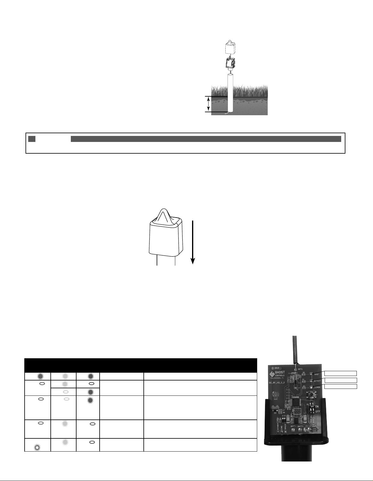
DIG A HOLE FOR THE PVC PIPE THAT HOLDS THE CONTROL BOARD AND BATTERIES:
A. Dig a hole 5"–6"deep for the PVC Pipe.
B. Optional: Rebar can be used as additional stability and support for the PVC Pipe and Control Unit.
NOTE
Gate should be closed before proceeding to Step 5. If not, close the gate before continuing.
5. MAKE SURE GATE IS TURNED ON AND TEST THE SENSOR BY DRIVING YOUR
VEHICLE DOWN THE DRIVEWAY:
A. INSTALL THE C-SIZED BATTERIES BACKSIDE OF THE CONTROL BOARD and observe that ALL LED’s turn ON for 1 second then
turn o.
B. Once sensor calibrates for 3 minutes then slowly drive past the Sensor Probe and verify that the Wireless Vehicle Sensor opens the gate.
C. Reinstall the cover for the Control Board.
6. FILL IN THE TRENCH AND HOLE:
A. After verifying that the vehicle sensor is functioning properly, TURN OFF the gate opener because a moving shovel can trip
the sensor and open your gate.
B. Fill in the trenches and the hole with dirt.
C. Turn on the gate opener. Operate the gate normally.
D. Check condition of batteries several times throughout the year and replace batteries as needed.
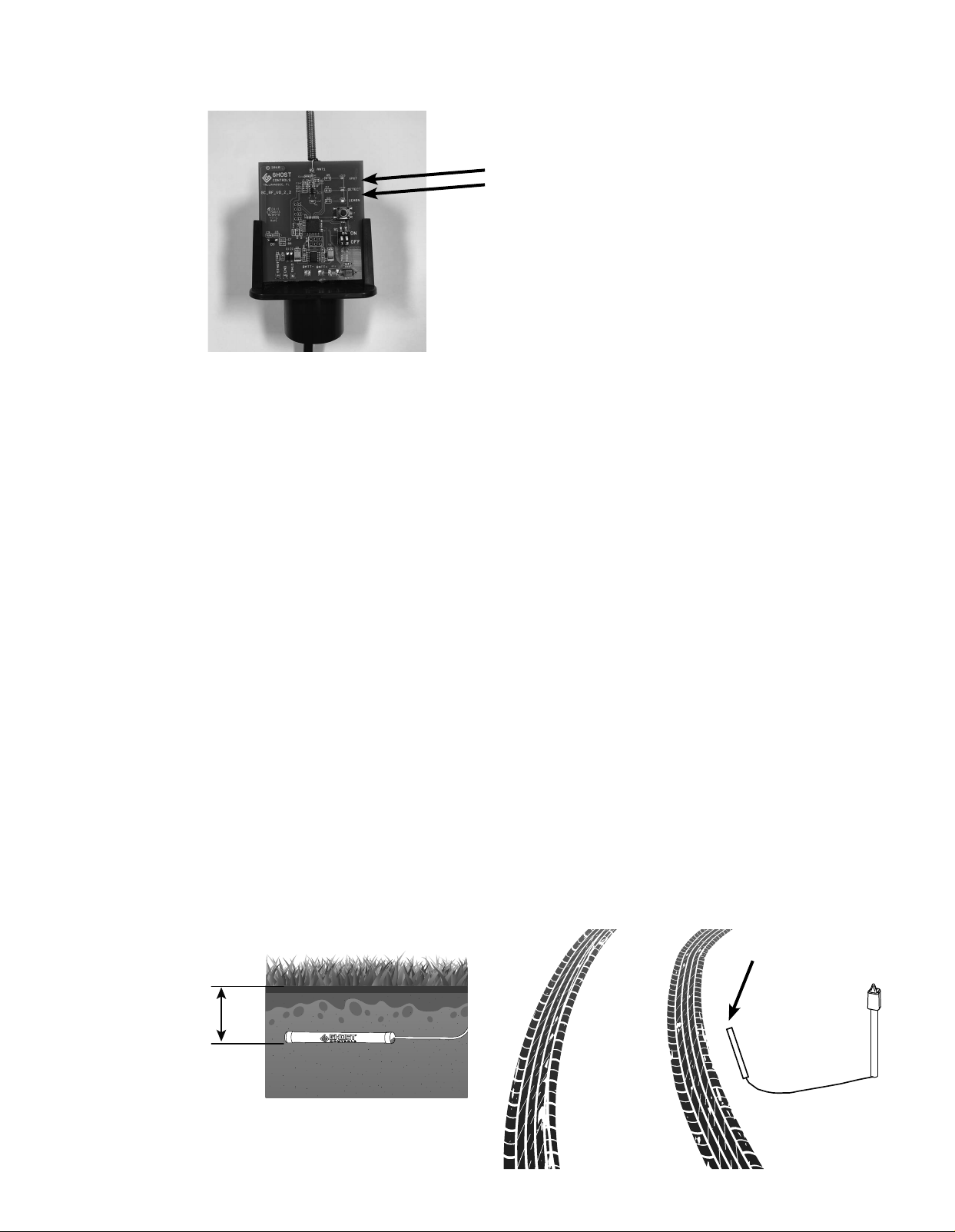
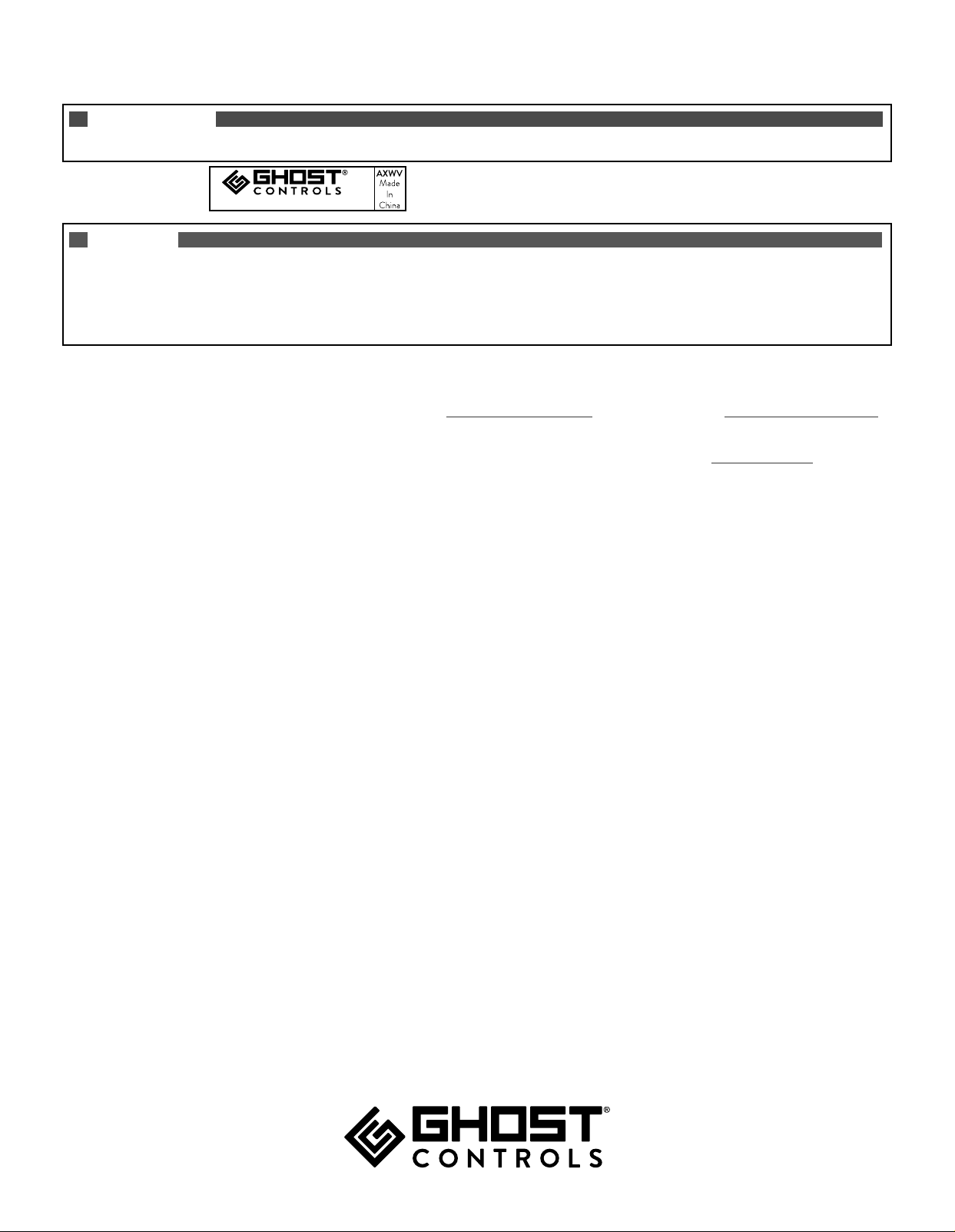
GUIDE TO LEDS
XMIT
(Green Led)
DETECT
(Yellow Led)
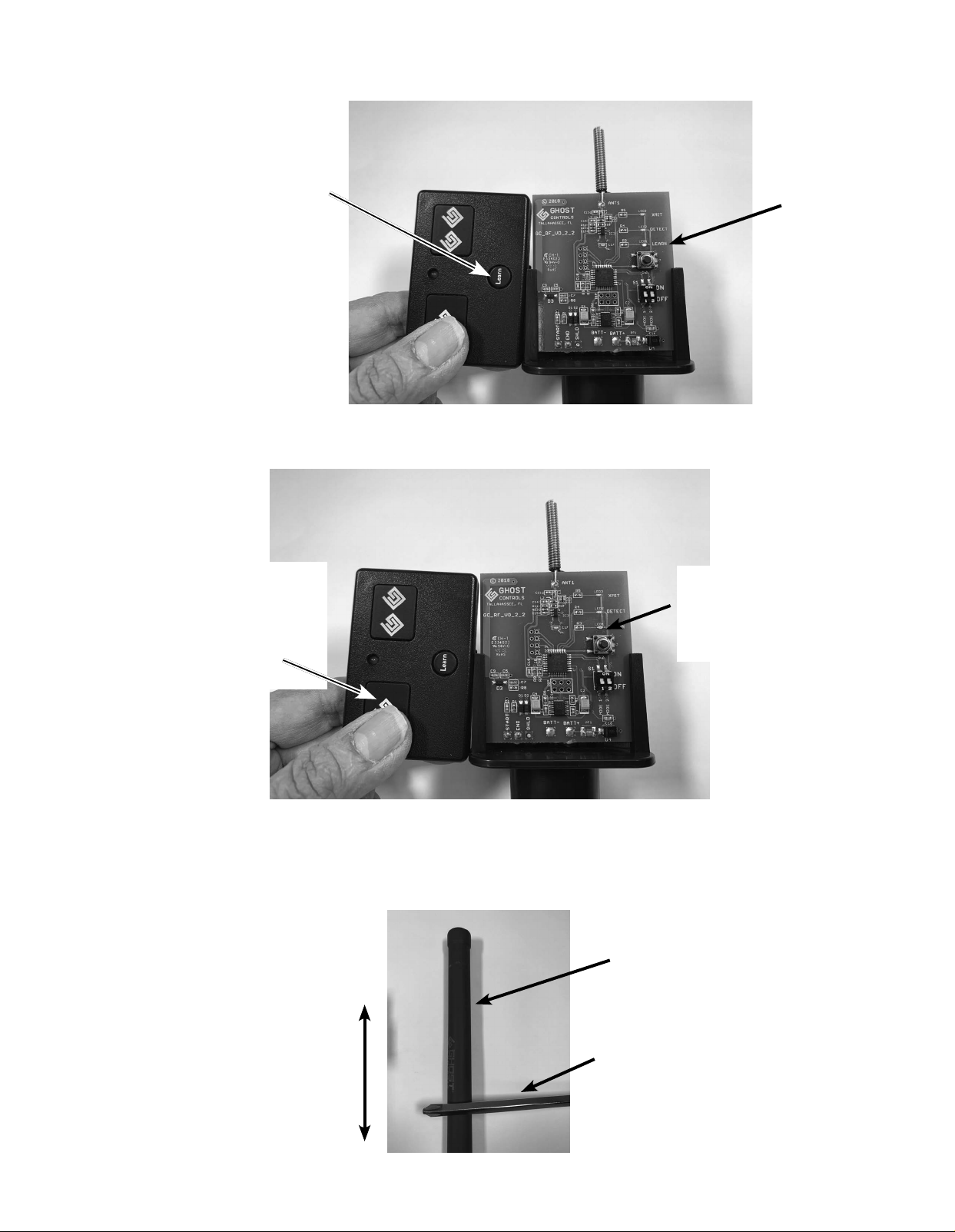
LEARN
(Red Led) MODE DESCRIPTION
ON ON ON POWER ON RESET All LEDs will be ON for 1 second when batteries are inserted.
OFF ON OFF CALIBRATING Yellow and RED LEDs will be alternating (Yellow=ON,
Red=OFF or Yellow=OFF, Red=ON) while unit is calibrating.
OFF ON
OFF OFF ON LEARN
TRANSMITTER
Red LED is ON when LEARN button is pressed for 3
seconds. Unit is in LEARN TRANSMITTER mode and
awaiting transmitter signal. Red LED will turn o once the
transmitter signal is learned or 60 seconds has elapsed.
OFF ON OFF DETECTED Yellow LED is ON for ~3 seconds when “moving vehicle”
is detected. Transmitting to follow. NOTE: Pressing and
releasing the LEARN button will simulate vehicle detection.
BLINKING ON OFF TRANSMITTING Green LED is blinking for ~3 seconds when unit is
transmitting OPEN command to Ghost Controls receiver.
Approximately 5–6 inches deep
Slide Cover Down
to Install for Use
XMIT=GREEN LED
DETECT=YELLOW LED
LEARN=RED LED