GIA GIATSU GIA-XK46 Service manual

GIA-XK46
OWNER’S & INSTALLATION
MANUAL
WIRED CONTROLLER
Thanks for choossing our product.
Please, read carefully this manual
before using the product
ENGLSIH

Wired controller GIA-XK46
2
To Users
Thank you for selecting GIATSU product. Please read this
instruction manual carefully before installing and using the product, so
as to master and correctly use the product. In order to guide you to
correctly install and use our product and achieve expected operating
effect, we hereby instruct as below:
(1) This appliance is not intended for use by persons (including
children) with reduced physical, sensory or mental capabilities,
or lack of experience and knowledge, unless they have been
given supervision or instruction concerning use of the appliance
by a person responsibility for their safety. Children should be
supervised to ensure that they do not play with the appliance.
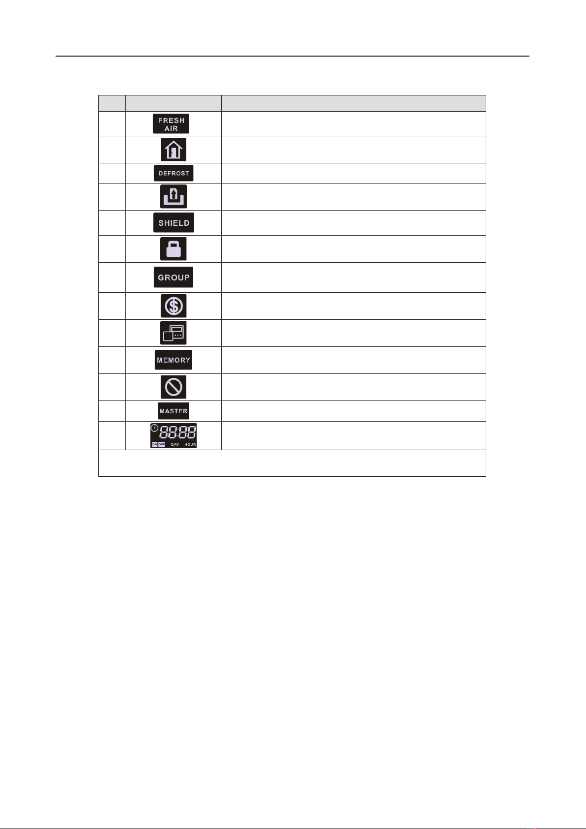
(2) This instruction manual is a universal manual, some functions
are only applicable to particular product. All the illustrations and
information in the instruction manual are only for reference, and
control interface should be subject to actual operation.
(3) In order to make the product better, we will continuously
conduct improvement and innovation. We have the right to
make necessary revision to the product from time to time due to
the reason of sales or production, and reserve the right to revise
the contents without further notice.
(4) For personal injury or property loss and damage caused by
improper operation such as improper installation and debugging,
unnecessary maintenance, violation of related national laws
and rules and industrial standard, and violation of this
instruction manual, etc., we will bear no liability.
(5) The final right to interpret for this instruction manual belongs to
GIATSU.
This marking indicates that this product should not
be disposed with other household wastes throughout the
EU. To prevent possible harm to the environment or human
health from uncontrolled waste disposal, recycle it
responsibly to promote the sustainable reuse of material
resources. To return your used device, please use the
return and collection systems or contact the retailer where the product
was purchased. They can take this product for environmental safe
recycling.

Wired controller GIA-XK46
3
Contents
1 SAFETY NOTICES (PLEASE BE SURE TO ABIDE )...............4
2 OPERATION NOTICES .........................................................5
3 DISPLAY................................................................................6
3.1 LCD OF WIRED CONTROLLER................................................. 7
3.2 LCD DISPLAY INSTRUCTION................................................... 8
4 BUTTONS..............................................................................9
4.1 BUTTON GRAPHICS..................................................................9
4.2 FUNCTION INSTRUCTION OF BUTTONS ................................ 9
5 INSTALLATION AND COMMISSIONING..............................10
5.1 INSTALLATION OF WIRED CONTROLLER..............................12
5.2 COMMISSIONING .................................................................... 18
6OPERATION INSTRUCTIONS .............................................28
6.1 ON/OFF......................................................................................28
6.2 MODE SETTING....................................................................... 28
6.3 TEMPERATURE SETTING....................................................... 29
6.4 FANSETTING........................................................................... 30
6.5 TIMER SETTING........................................................................31
6.6 SWING SETTING...................................................................... 38
6.7 QUIET SETTING....................................................................... 39
6.8 SLEEP SETTING ...................................................................... 42
6.9 AIR SETTING*........................................................................... 43
6.10 LIGHT ON/OFF SETTING....................................................... 45
6.11 SAVE SETTING....................................................................... 46
6.12 FILTER CLEAN REMINDER SETTING .................................. 48
6.13 X-FANSETTING ..................................................................... 51
6.14 ABSENCE SETTING............................................................... 52
6.15 REMOTE SHIELD FUNCTION ............................................... 52
6.16 CHILD LOCK FUNCTION ....................................................... 53
6.17 GATE-CONTROL FUNCTION ................................................53
7 ERROR DISPLAY.................................................................53
7.1 TABLEOF ERROR CODES FOR OUTDOOR UNIT ................ 54
7.2 TABLEOF ERROR CODESFOR INDOOR UNIT .................... 56
7.3 TABLEOF DEBUGGING CODES............................................. 57
7.4 TABLEOF STATUSCODES ..................................................... 58

Wired controller GIA-XK46
4
Wired Controller XK46
1
1 SAFETY NOTICES (PLEASE BE SURE TO
ABIDE )
Warning: If not abide strictly, it may cause severe damage to the unit or
the people.
Note: If not abide strictly, it may cause slight or medium damage to the unit
or the people.
This sign indicates that the operation must be prohibited. Improper
operation may cause severe damage or death to people.
This sign indicates that the items must be observed. Improper operation
may cause damage to people or property.
WARNING!
This product can’t be installed at corrosive , inflammable or explosive
environment or the place with special requirements, such as kitchen. Otherwise, it
will affect the normal operation or shorten the service life of the unit, or even cause
fire hazard or serious injury. As for above special places, please adopt special air
conditioner with anti-corrosive or anti-explosion function .

Wired controller GIA-XK46
5
Wired Controller XK46
2
2 OPERATION NOTICES
◆The power supply for all indoor units must be unified.
◆Prohibit installing the wired controller at wet or sunshine places.
◆Do not knock, throw or frequently disassemble the wired controller.
◆Do not operate the wired controller with wet hands.
◆In one system network, you must set one indoor unit as the master indoor unit,
Other indoor units are slave indoor units .
◆The operation mode of the system is basing on that of master indoor unit.
Master indoor unit can switch to any modes, while slave unit can’t switch to the
mode that is conflicting with master indoor unit.
◆When master indoor unit changes mode which cause operation mode of
slave indoor unit conflicts with that of system, the operation mode of slave unit
will switch to the operate mode of system automatically.
◆When two wired controllers control one (or more) indoor unit(s), the address of
wired controller should be different.
◆Functions with “*”are optional for indoor units. If a function is not included in an
indoor unit, wired controller can’t set the function, or setting of this function is
invalid to the indoor unit.

Wired controller GIA-XK46
6
Wired Controller XK46
3
3 DISPLAY
Fig. 3.1 Appearance of wired controller
3.1 LCD OF WIRED CONTROLLER
Fig. 3.2 LCD graphics of wired controller

Wired controller GIA-XK46
7
4
3.2 LCD DISPLAY INSTRUCTION
Table 3.1 LCD display instruction
No. Symbols Instructions
1 Up and down swing function
2 *Left and right swing function
3
It's valid under Save mode and displays during setting process.
Temperature lower limit for Cooling: Limit the minimum
temperature value under Cooling or Dry mode.
Temperature upper limit for Heating: Limit the maximum
temperature value under Heating, Space Heating or 3D Heating
mode.
4 *
Auto mode (Under Auto mode, the indoor units will
automatically select their operating mode as per the
temperature
change so as to make the ambient comfortable.)
5
It shows the setting temperature value(In case the wired
controller is controlling a Fresh Air Indoor Unit, then the
temperature zone will display FAP)
6 Cooling mode
7 Dry mode
8 Fan mode
Heating mode
Wired Controller XK46
5
9Instructions
10 When inquiring or setting project number of indoor unit, it
displays "NO." icon
11 *Floor Heating mode (When Heating and Floor Heating
simultaneously shows up, it indicates 3D Heating is activated.)
12 Display "SET" icon under parameter setting interface
13 *Space Heating mode
14 Display "CHECK" icon under parameter view interface
15 Outdoor unit operates under Save mode/upper limit of system
capacitor less 100%/remote Save status
16 Sleep status
17
Current set fan speed (including auto, low speed, medium-low
speed, medium speed, medium-high speed, high speed
and turbo seven status)
18 *Air status, Indoor unit optional function
19 Remind to clean the filter
20 Quiet status (including Quiet and Auto Quiet two status)
21 Light On/Off function
22 X-fan function
23 *Health function, Indoor unit optional function

Wired controller GIA-XK46
8
Wired Controller XK46
6
No.
Symbols
Instructions
24 *Reserved function
25 Absence function
26 Outdoor unit defrosting status
27 Gate-control function
28 Shielding status
29 Child Lock status
30 One wired controller controls multiple indoor units
31 Save status of indoor unit
32 It indicates the current wired controller is the slave wired
controller (address of wired controller is 02)
33 Memory status (The indoor unit resumes the original setting
state after power failure and then power recovery)
34 Invalid operation
35 Current wired controller connects master indoor unit
36 Timer zone:Display system clock and timer status
Note: When wired controller is connected with different indoor units, some functions will be
different

Wired controller GIA-XK46
9
Wired Controller XK46
7
4 BUTTONS
4.1 BUTTON GRAPHICS
Fig. 4.1 Button graphics
4.2 FUNCTION INSTRUCTION OF BUTTONS
Table 4.1 Function instruction of buttons
No. Buttons Instructions
1 ENTER/CANCEL Select and cancel function
2
(1) Set operating temperature of indoor unit
(2) Set Timer
(3) Switch Quiet mode, Air grade, Clean grade, set upper
and lower temperature limit under Save mode
(4) Set and inquiry parameter
5
Wired Controller XK46
8
No.
Buttons
Instructions
3 SLEEP Set Sleep mode
4 FAN
Switch among auto, low speed, low-medium speed,
medium speed, medium-high speed, high speed and
turbo status
6 MODE
Switch Auto,Cooling, Dry, Fan, Heating, Floor Heating,
3D Heating and Space Heating modes for indoor unit.
(Note: The Floor Heating, 3D Heating and Space Heating
function icon will show up when the unit has those
functions.)
7 FUNCTION Switch among Air, Quiet, Light, Health, Absence, Save,
Clean, and X-fan functions.
8 TIMER Timer setting
9 SWING Set up and down swing status
10 ON/OFF Indoor unit On/Off
2+5 + Simultaneously press “ ” and “ ” for 5s to enter or
cancel the Child Lock function.
5 INSTALLATION AND COMMISSIONING
There’re two editions of wired controller. The parts of wired controller are
different.
Edition one :

Wired controller GIA-XK46
10
Wired Controller XK46
Fig. 5.1.1 Parts of wired controller
No. 1 2 3
Name Panel of wired
controller
Self-tapping Screw ST3.9X25
MA
Soleplate of wired
controller
Q'ty 1 3 2
Wired Controller XK46
8
No.
Buttons
Instructions
3
SLEEP
Set Sleep mode
4
FAN
Switch among auto, low speed, low-medium speed,
medium speed, medium-high speed, high speed and
turbo status
6
MODE
Switch Auto,Cooling, Dry, Fan, Heating, Floor Heating,
3D Heating and Space Heating modes for indoor unit.
(Note: The Floor Heating, 3D Heating and Space Heating
function icon will show up when the unit has those
functions.)
7
FUNCTION
Switch among Air, Quiet, Light, Health, Absence, Save,
Clean, and X-fan functions.
8
TIMER
Timer setting
9
SWING
Set up and down swing status
10
ON/OFF
Indoor unit On/Off
2+5
+
Simultaneously press “ ” and “ ” for 5s to enter or
cancel the Child Lock function.
5 INSTALLATION AND COMMISSIONING
There’re two editions of wired controller.The parts of wired controller are
different.
Edition one :

Wired controller GIA-XK46
11
Wired Controller XK46
Edition Two :
Fig. 5.1.2 Parts of wired controller
No.
1
2
3
4
Name
Panel of wired
controller
Self-tapping Screw
ST3.9X25 MA
Screw M4×25
Soleplate of wired
controller
Q'ty 1 3 2 1

Wired controller GIA-XK46
12
Wired Controller XK46
11
5.1 INSTALLATION OF WIRED CONTROLLER
5.1.1 Communication Line Selection
Fig. 5.2 Length of communication line
Wire material
type
Total length of
communication line
between indoor unit
and wired controller
L (m/feet)
Wire size
(mm2/AW
G)
Material
standard Remarks
Light/Ordinary
Polyvinyl
chloride
sheathed
cord.
(60227 IEC 52
/60227 IEC
53)
L≤250m
(L≤820-1/5feet)
2×0.75
mm2~2×
1.25 mm2
(2×AWG1
8~2×AWG
16)
IEC
60227-5:2
007
(1)Total length of
communication line can't
exceed 250m (820-1/5feet).
(2)The cord shall be Circular
cord (the cores shall be
twisted together).
(3)If unit is installed in
places with intense
magnetic field or strong
interference, it is necessary
to use shielded wire.
Note:
①If the air conditioner is installed at the strong electromagnetic interference
place, communication line of the wired controller must use shielding
twisted pair.

Wired controller GIA-XK46
13
Wired Controller XK46
12
②Materials of communication line for wired controller must be selected
according to this instruction manual strictly
5.1.2 Installation requirements
(1) Prohibit installing the wired controller at wet places.
(2) Prohibit installing the wired controller at direct sunshine places.
(3) Prohibit installing the wired controller at the place near high temperature
objects or water-splashing places.
(4) Prohibit installing the wired controller at the place where faces forward to the
window. Prevent abnormal work due to the interference from the other wired
controller around.
Wired Controller XK46
13
5.1.3 Wiring Requirements
There are four network wiring methods between wired controller and indoor unit:
Fig. 5.3 One wired controller controls Fig. 5.4 Two wired controllers control
one indoor unit one indoor unit

Wired controller GIA-XK46
14
Wired Controller XK46
14
Fig. 5.5 One wired controller controls multiple indoor units simultaneously
Wired Controller XK46
Fig. 5.6Two wired controllers control multiple indoor units simultaneously
Wiring instructions:
(1) When one wired controller controls multiple indoor units simultaneously, the
wired controller can connect to any one indoor unit, but the connected indoor
unit must be the same series indoor unit. The total quantity of indoor unit
controlled by wired controller can't exceed 16 sets, and the connected indoor
unit must be within the same indoor unit's network. Wire controller must set
quantity of group control indoor units. Please refer to 5.2.3 Parameters Setting.
(2) When two wired controllers control one indoor unit, the addresses of those two
wired controllers should be different. Please refer to 5.2.3 parameter setting.

Wired controller GIA-XK46
15
Wired Controller XK46
16
(3) When two wired controllers control multiple indoor units, wired controller can
connected to any one indoor unit, while the connected indoor unit should be
the same series indoor unit. The addresses of those two wired controllers
should be different. Please refer to 5.2.3 parameter setting. The total quantity
of indoor unit controlled by wired controller can't be more than 16 sets and all
connected indoor units must be within the same indoor unit network. Wire
controller must set quantity of group control indoor units. Please refer to 5.2.3
Parameters Setting.
(4) When one (or two) wired controller(s) control(s) multiple indoor units at the
same time, the controlled indoor unit's setting should be the same.
(5) Wiring of wired controller and indoor unit network must be according to one of
the four wiring method as shown in fig 5.3-5.6. As for the connection method
shown in fig 5.4 and 5.6, there should be only one master wired controller
(address is 01) and one slave wired controller (address 02). The quantity of
wired controller can't exceed two.
Note:
Series of indoor units include:①Common Multi VRF Units;②Fresh Air Units;③
Double-heat Sources Units;④Combined Units; Except for fresh air units,
double-heat sources units and combined units, the rest of indoor units belong to
common multi VRF units.

Wired controller GIA-XK46
16
Wired Controller XK46
17
5.1.4 Installation
There’re two editions of wired controller. The Installation way is different.
Installation way one :
Fig. 5.7 Installation diagram for wired controller

Wired controller GIA-XK46
17
Wired Controller XK46
18
Fig. 5.7 is the simple installation process of wired controller; please pay
attention to the following items:
(1) Before installation, please cut off the power for indoor unit.
(2) Pull out the two-core twisted pair from the installation hole on wall, and then
pull this wire through the " ” shape hole at the rear side of Soleplate of wired
controller.
(3)Stick the bottom plate of wired controller on the wall and then use Self-tapping
Screw ST3.9X25 MA to fix Soleplate and installation hole on wall together.
(4)Connect two-core twisted pair to H1 and H2 wiring column and then fix the
screws.
(5) Set two-core into the groove at left side of wiring column, and then bundle
panel and Soleplate of wired controller together.
Note: If the wire size of the selected communication line is too large, you can peel
some sheath layer of communication wire to satisfy installation requirements.
Installation way two :
Wired Controller XK46
19
Fig. 5.8 Installation diagram for wired controller
Fig. 5.8 is the simple installation process of wired controller; please pay
attention to the following items:
(1) Before installation, please cut off the power for indoor unit.
(2) Pull out the two-core twisted pair from the installation hole on wall, and then
pull this wire through the " ” shape hole at the rear side of Soleplate of wired
controller.

Wired controller GIA-XK46
18
Wired Controller XK46
20
(3)Stick the bottom plate of wired controller on the wall and then use Self-tapping
Screw ST3.9X25 MA or Screw M4×25 to fix Soleplate and installation hole on
wall together.
(4) Connect two-core twisted pair to H1 and H2 wiring column and then fix the
screws.
(5) Tidy up the lines in slot on the back of the panel, and then bundle the front
panel of wired controller to its soleplate and the installation is completed.
Note: If the wire size of the selected communication line is too large, you can peel
some sheath layer of communication wire to satisfy installation requirements.
5.1.5 Disassembly
Fig. 5.9 Disassembly diagram of wired controller
Wired Controller XK46
21
5.2 COMMISSIONING
5.2.1 Set Master Indoor Unit
Under Off status, long press MODE button for 5s to set the corresponding
indoor unit of wired controller as master indoor unit. “MASTER” icon will be light
after finishing setting.
Note:
①There is a master indoor unit in a system, other slave indoor units can be set
as master unit, in which case, the original master unit will become a slave
unit.
②In one system, only one set of master indoor unit is allowed. If system detects
that there are several master units, it will designate the unit with the smallest
project number as a master unit.
5.2.2 Parameter Enquiry
Unit parameters can be checked in unit On or Off status.
(1) Long press “FUNCTION” button for 5s to enter the interface of viewing unit
parameters. “C00” is displayed in temperature zone and “CHECK” icon is light;
(2) Press “ ” or “ ” button to select parameter code;
(3) Press “ENTER/CANCEL” button to return to last step until exits viewing
parameters.
The parameter enquiry list is as following:

Wired controller GIA-XK46
19
Wired Controller XK46
Table 5.1 Parameters viewing list
Parameter
code
Parameter
name
Parameter
range Viewing method
C00
Entrance of
adjustable
parameter
--
In “C00” status, Timer zone shows the current indoor
unit project number. When one wired controller is
controlling multiple indoor units, then only the
smallest project number will be displayed.
C01
View the
project
number of
indoor unit
and locate
the faulted
indoor unit
1-255;
Project
number of
online
indoor unit
Operation method:
Enter viewing, press MODE button in “C01” status to
enter the interface of viewing indoor unit project
number. Press “ ” or “ ” button to select the
project number of indoor unit.
Display method:
Temperature zone: displays error codes of the
current indoor unit( The temperature zone will
display the error codes in turn with an interval of 3
seconds if there are several malfunctions in one
indoor unit.)
Timer zone: displays present indoor unit project
number /C5 malfunction of project number conflict
Note:
1) If master indoor unit exists in current indoor unit
network, “MASTER” icon will be bright under “C01”
interface. After entering the interface of viewing
project number, “MASTER” icon will be bright only
when the project number of master indoor unit is
selected.
2) System will not exit “C01” viewing automatically.
User has to exit this interface manually.
C03
View the
indoor unit
quantity of
the system
network
1-80 Timer zone: display indoor unit quantity of the
system
Wired Controller XK46
21
5.2 COMMISSIONING
5.2.1 Set Master Indoor Unit
Under Off status, long press MODE button for 5s to set the corresponding
indoor unit of wired controller as master indoor unit. “MASTER” icon will be light
after finishing setting.
Note:
①There is a master indoor unit in a system, other slave indoor units can be set
as master unit, in which case, the original master unit will become a slave
unit.
②In one system, only one set of master indoor unit is allowed. If system detects
that there are several master units, it will designate the unit with the smallest
project number as a master unit.
5.2.2 Parameter Enquiry
Unit parameters can be checked in unit On or Off status.
(1) Long press “FUNCTION” button for 5s to enter the interface of viewing unit
parameters. “C00” is displayed in temperature zone and “CHECK” icon is light;
(2) Press “ ” or “ ” button to select parameter code;
(3) Press “ENTER/CANCEL” button to return to last step until exits viewing
parameters.
The parameter enquiry list is as following:

Wired controller GIA-XK46
20
Wired Controller XK46
23
Parameter
code
Parameter
name
Parameter
range
Viewing method
C06 View priority
operation
00: normal
operation
01: priority
operation
Operation method:
Enter viewing: press MODE button in “C06” status to
enter the interface of viewing priority operation.
Press “ ” or “ ” button to select indoor unit.
Display method:
Temperature zone: displays current indoor unit
project number;
Timer zone: displays current priority operation
setting value of indoor unit.
C07
View indoor
ambient
temperature
--
Operation method:
Enter viewing: press MODE button in “C07” status to
enter the interface of viewing indoor ambient
temperature. Press “ ” or “ ” button to select
indoor unit.
Display method:
Temperature zone: displays current indoor unit
project number;
Timer zone: displays indoor ambient temperature.
C08
View Filter
Clean
Reminder
time
4-416:
days Timer zone: displays Filter Clean Reminder time
C09
View address
of wired
controller
01, 02 Timer zone: displays the address of wired controller
Table of contents
Other GIA Controllers manuals