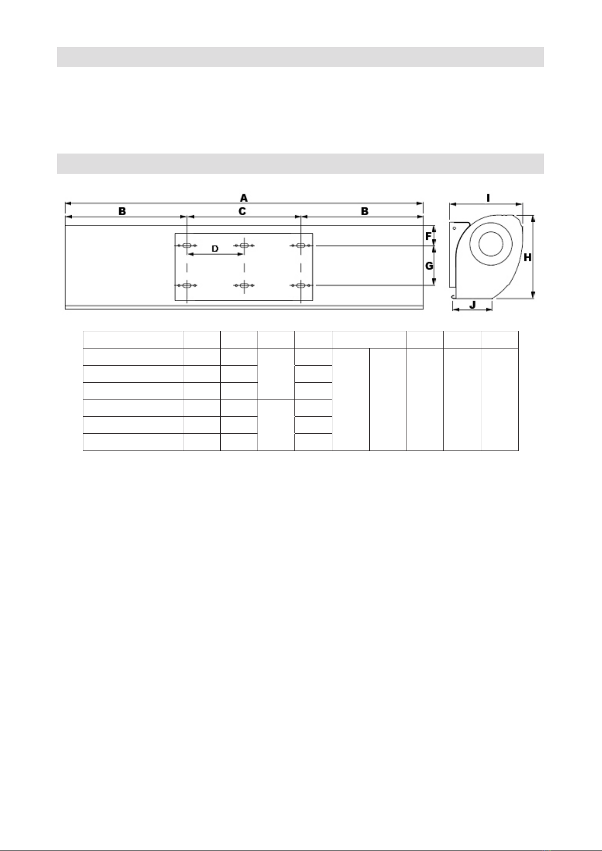
5. TECHNICAL PARAMETER
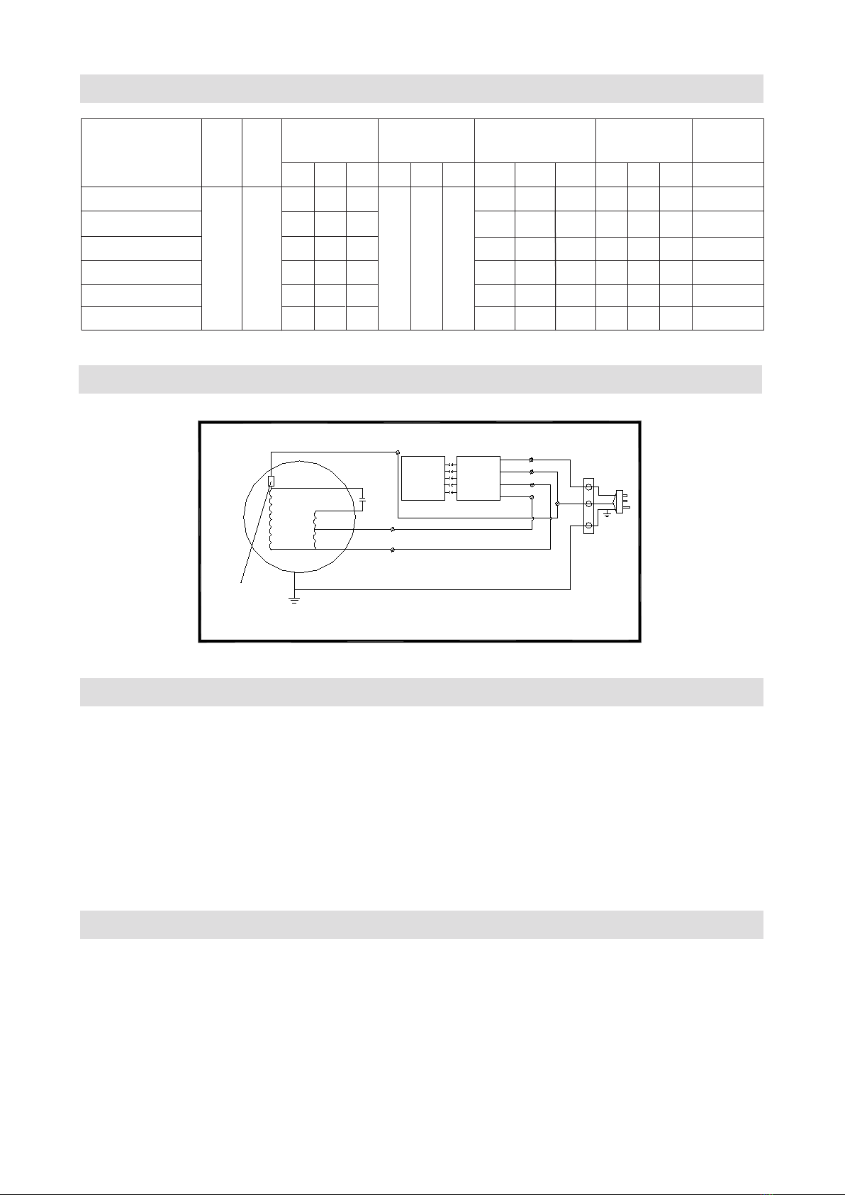
6. ELECTRIC WORK
7. OPERATION
7.1 Turn on the power switch on the unit.
Select the air speed: High [H], Middle [M], Low [L]
7.2 Turn on by remote controller.
One button to control the working cycle at:
Turn on at high speed – Middle speed – Low speed – turn off.
7.3 According to the installation place to adjust the wind direction parts to obtain
the best effect.
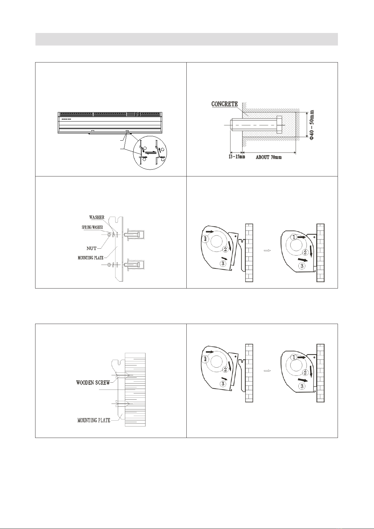
8. CAUTIONS
1. Turn off the interrupter or disconnect the plug for any maintenance service.
2. Turn off the interrupter or disconnect the plug in case of a non product use.
3. Make sure that the product provides a ground wire.
4. The pictures shown on this manual are illustrative only.
5. This appliance is not intended for use by persons (including children) with reduced
physical, sensory or mental capabilities, or lack of experience and knowledge, unless
they have been given supervision or instruction concerning use of the appliance by a per
son responsible for their safety.
THERMAL CUT-OUT
DOUBLE SPEED SWITCH WIRING DIAGRAM
YELLOW-GREEN
(YELLOW)
BLACK
WHITE
BLUE(BROWN/RED)
YELLOW
ORANGE
C
K
2OFF
3HI
1LO
L
N
DOUBLE SPEED INFRARED REMOTE CONTROLLED WIRING DIAGRAM
THERMAL CUT-OUT YELLOW-GREEN
WHITE
RECEIVER
I/O
BLUE(BROWN/RED)
C
YELLOW
BLACK
(YELLOW)
ORANGE
RECEIVER
I/C
GREY
WHITE
N
L
BROWN
BLUE
Max input power Max air speed Air volume Noise Net weight
MODEL Volt. Freq (W) (m/s) (m3/h) (dB) (Kg)
(V~) (Hz)
H M L H M L H M L H M L
GIA-AC9-1400SA1 160 110 70 1.400 1.100 900 57 55 53 10
GIA-AC10-1600SA1 180 130 90 1.600 1.300 1000 57 55 53 10,5
GIA-AC12-1900SA1 200 150 110 1.900 1.600 1.200 58 56 54 12
GIA-AC15-2500SA1 220 50 11 9 7
230 180 140 2.500 2.000 1.500 59 57 55 13,5
GIA-AC18-3200SA1 300 250210 3.200 2.500 1.800 60 58 56 15
GIA-AC20-3600SA1 350 300260 3.600 2.700 1.850 61 59 57 18