manuals.online logo
Brands
  1. Home
  2. •
  3. Brands
  4. •
  5. Giant
  6. •
  7. Water Pump
  8. •
  9. Giant GP7142 User manual

Giant GP7142 User manual

Contents:
Installation Instructions: page 2
Pump Specications: page 3
Exploded View: page 4
Parts List / Repair Kits: page 5
Repair Instructions: page 6
Recommended Spare
Parts List: page 6
Dimensions: page 7
Warranty Information: back page
Triplex Ceramic
Plunger Pump
Operation Manual
Model
GP7142
Updated 12/21
2
Safety Rules
Pump operation without safety valve as well
as any excess in temperature or speed limits
automatically voids the warranty. The safety
valve must be regulated in accordance with
the guidelines for liquid spraying units so that
the admissible operating pressure can not be
exceeded by more than 10%.
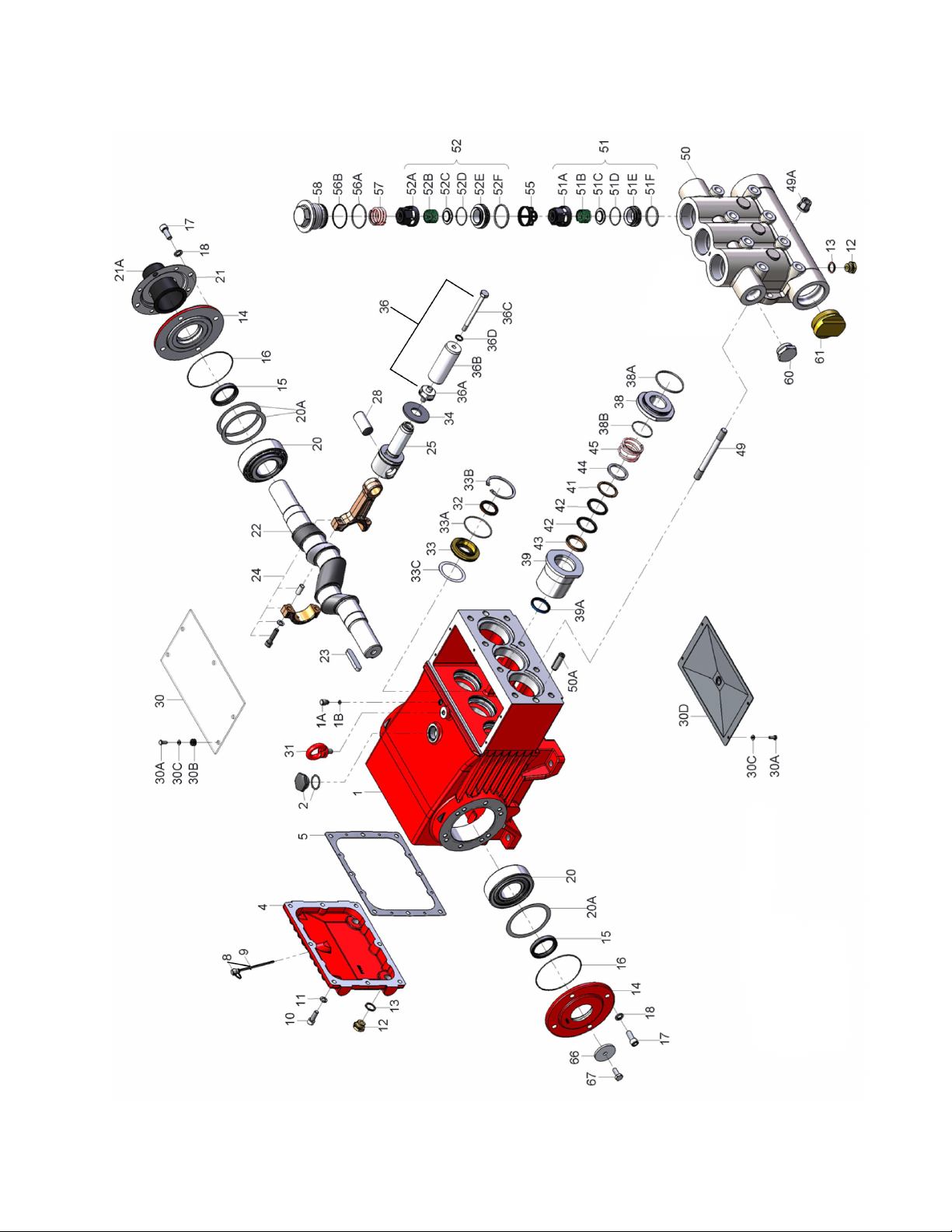
When the pump is in operation, the open shaft
end must be covered up by shaft protector (21)
and the driven shaft side and coupling by a bell
housing; the plunger room should have a cover
(30).
Before any maintenance to the pump takes
place, the pressure in discharge line and in
pump must be at zero. Close up suction line.
Disconnect fuses to ensure that the driving
motor does not get switched on accidently.
Make sure that all parts on the pressure side of
the unit are vented and relled, with pressure at
zero, before starting the pump.
In order to prevent air or an air/water-mixture
being absorbed and to prevent cavitation
occurring, the pump-npshr (positive suction head
and water temperature) must be kept under
control.
Cavitation and/or compression of gases
lead to uncontrollable pressure-kicks which
can ruin pump and unit parts and also
be dangerous to the operator or anyone
standing nearby.
Giant plunger pumps are suitable for pumping
clean water and other non-aggressive or
abrasive media with a specic weight similar to
water.
Before pumping other liquids - especially
inammable, explosive and toxic media
- the pump manufacturer must, under all
circumstances, be consulted with regard to
the resistance of the pump material. It is the
responsibility of the equipment manufacture
and/or operator to ensure that all pertinent
safety regulations are adhered to.
Standard pump with valve casing of seawater-
resistant-bronze.
Figures given for maximum pressure and maximum
speed (rpm) apply to interval operation. When the
pump is used in continual operation and/or with
water warmer than 104°F (40°C), these values must
be reduced by 10%.
Required NPSH refers to water: Specic weight
1kg/dm3, viscosity 1oE at maximum permissible
revolutions, using both suction connections.
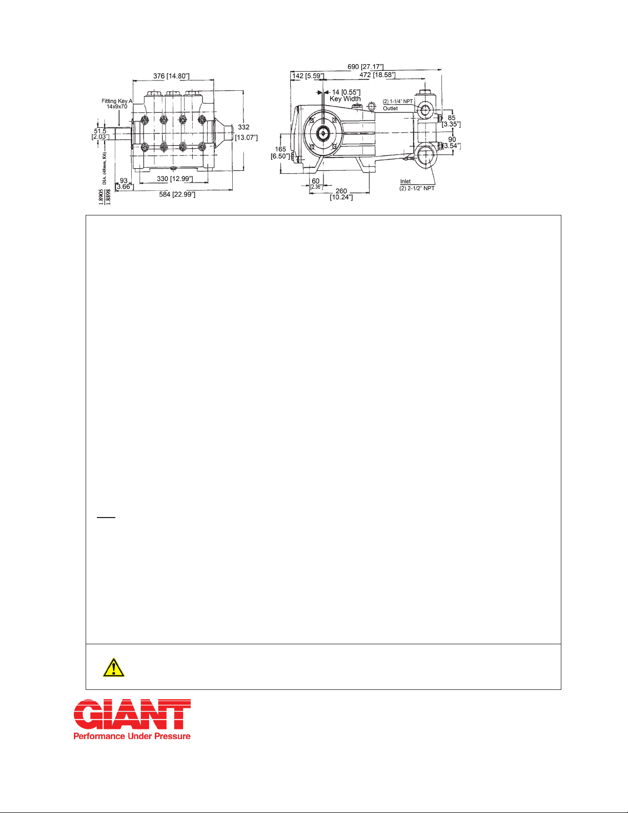
IMPORTANT! Use of both suction connections
is imperative in order to ensure cavitation-free
operation and optimal suction conditions. If only one
connection is used, a safety margin of one meter
has to be added to the required NPSH.
Operation and Maintenance
Check oil level prior to starting and ensure trouble-
free water supply.
IMPORTANT! If there is a danger of frost,
the water in the pump and in the pump ttings
(particularly the unloader valve) must be emptied.
The second discharge port can also be used and the
pump run “dry” for 1-2 minutes for this purpose.
Oil amount: 1.6 gallons (6.0 litres). Only use
Giant’s p/n 01154 or ISO VG 220 industrial gear
oil (e.g. Aral Degol BG220) or automobile gear oil
SAE 90 GL4.
We recommend ISO VG 68 (SAE80) gear oil for low
ambient temperatures (+41°F/5°C and less).
Initial change after 50 operating hours and then
every 1000 operating hours, or after 1 year if used
less.
IMPORTANT! When operating in damp places
or with high temperature uctuations, oil must be
changed immediately, should condensate (frothy oil)
occur in the gear box.
IMPORTANT! If the pump is mounted on a vehicle
(possibility of unlevelness) and/or if the pump speed
is between 300 rpm and 500 rpm, the oil quantity is
1.8 gallons (7.0 liters). To check, put the oil dipstick
in the bore situated beside the eye bolt.
Keep NPSH under control.
Maximum input pressure 145 PSI (10 bar),
maximum suction head -4.35 PSI (-0.3 bar). Make
sure that suction pulsation is su󰀩ciently dampened –
water column resonance must be avoided.
INSTALLATION INSTRUCTIONS
PULLEY INFORMATION
Pulley selection and pump speed are based on
a 1725 RPM motor and “B” section belts. When
selecting desired GPM, allow for a ±5% tolerance
on pumps output due to variations in pulleys, belts
and motors among manufacturers.
1. Select GPM required, then select appropriate
motor and pump pulley from the same line.
2. The desired pressure is achieved by selecting
the correct nozzle size that corresponds with the
pump GPM.
U.S. (Metric)
Volume* ................................................. 38.4 GPM .................... (145.2 LPM)
Discharge Pressure*.............................. 2610 PSI....................... (180 bar)
Power Consumption .............................. 69.0 BHP ...................... 51.5 kW
Speed ........................................................................................... 700 RPM
Inlet Pressure (maximum)...................... -4.35 to 140 PSI ........... (-0.3 to 10 bar)
Plunger Diameter................................... 1.7” ............................... 42mm
Plunger Stroke....................................... 2.0” ............................... 52mm
Crankshaft Diameter.............................. 1.9” ............................... 48mm
Key Width .............................................. 0.6” ............................... 14mm
Crankshaft Mounting..................................................................... Either side
Shaft Rotation........................................ Top of pulley towards manifold
Temperature of Pumped Fluids* ............ Up to 140 oF ................. (60 oC)
Inlet Ports...................................................................................... (2) 2-1/2” NPT
Discharge Ports ............................................................................ (2) 1-1/4” NPT
Weight.................................................... 375 lbs. ........................ (170 kg)
Crankcase Oil Capacity ......................... 1.6 Gal. ........................ (6.0 liter)
Fluid End Material......................................................................... Cast Iron
NPSHR .................................................. 28 feet of head.............. 8.5 meters of head
*For continuous duty and/or with uid temperature above 104°F (40°C), reduce pressure and
ow by 10%
Specications
Model GP7142
Consult the factory for special requirements that must be met if the
pump is to operate beyond one or more of the limits specied above.
HORSEPOWER INFORMATION
Horsepower ratings shown are the power re-
quirements for the pump. Gas engine power
outputs must be approximately twice the
pump power requirements shown above.
We recommend that a 1.15 service factor be
specied when selecting an electric motor as
the power source. To compute specic pump
horsepower requirements, use the following
formula:
(GPM X PSI) / 1450 = HP
3
GP7142 HORSEPOWER REQUIREMENTS
RPM GPM 800 PSI 1000 PSI 1500 PSI 2000 PSI 2610 PSI
300 16.5 9.1 11.4 17.1 22.8 29.7
400 21.9 12.1 15.1 22.7 30.2 39.4
500 27.4 15.1 18.9 28.3 37.8 49.3
600 32.9 18.2 22.7 34.0 45.4 59.2
700 38.4 21.9 27.4 41.1 54.9 69.1
4
Exploded View - GP7142
ITEM PART DESCRIPTION QTY.
1 07600 Crankcase 1
1A 05525 Head of Oil Dipstick 1
1B 01009 O-Ring 1
2 13000 Oil Filler Plug Assembly 1
4 07601 Crankcase Cover 1
5 05798 Gasket, Crankcase Cover 1
8 07603 Oil Dip Stick Assembly 1
9 01009 O-Ring, Dip Stick 1
10 22706 Hexagon Screw 8
11 06725 Spring Washer 8
12 07109 Drain Plug 3
13 06272 Copper Seal Ring 3
14 05644 Bearing Cover 2
15 07608 Radial Shaft Seal 2
16 07184 O-Ring 2
17 05642 Hexagon Socket Screw 8
18 05039 Spring Washer 8
20 07610 Taper Roller Bearing 2
20A 07611 Fitting Disc (Shim) 1-5
21 05645 Shaft Guard Holder 1
21A 05646 Shaft Guard 1
22 13405 Crankshaft 1
23 07614 Key 1
24 13182 Connecting Rod Assembly 3
25 13183 Crosshead Assembly 3
28 13184 Crosshead Pin 3
30 07619 Cover Plate 1
30A 07225-0100 Hexagon Screw 8
30B 13136 Grommet 4
30C 08280 Washer 8
30D 13154 Cover Plate 1
31 07623 Eye Bolt 1
32 07624 Radial Shaft Seal 3
33 07626 Seal Retainer 3
33A 07627 O-Ring 3
33B 07628 Circlip 3
33C 07249 Shim 3
34 13137 Oil Scraper 3
36 04316 Plunger Pipe Assy., (36 A-D) 3
36A 07667 Plunger Connection 3
36B 04317 Plunger Pipe 3
36C 07664 Tension Screw 3
PARTS LIST - GP7142
5
REPAIR KITS - GP7142
ITEM PART DESCRIPTION QTY.
36D 07665 Copper Ring 3
38 04321 Seal Case 3
38A 13156 O-Ring 3
38B 13141 O-Ring 3
39 04322 Seal Sleeve 3
39A 04323 Compact Ring 3
41 07446 Support Ring 3
42 07745 V-Sleeve 6
43 07744 Pressure Ring 3
44 04324 Spacer Ring 3
45 13297 Tension Spring 3
49 13159 Stud Bolt 8
49A 13160 Hex Nut 8
50 07790 Valve Casing 1
50A 13162 Cylinder Stud 2
51 05594 Inlet Valve Assembly
(51A-51F) 3
51A 05595 Spring Tension Cap 3
51B 05450 Valve Spring 3
51C 05247 Valve Plate 3
51D 05596 O-Ring 3
51E 05597 Inlet Valve Seat 3
51F 05166 O-Ring 3
52 05600 Discharge Valve Assembly
(52A-52F) 3
52A 05595 Spring Tension Cap 3
52B 05450 Valve Spring 3
52C 05247 Valve Plate 3
52D 05596 O-Ring 3
52E 05598 Discharge Valve Seat 3
52F 05599 O-Ring 3
55 05647 Valve Retainer 3
56A 07658 O-Ring 3
56B 07635 Support Ring 3
57 13173 Tension Spring 3
58 06682 Plug 3
60 12251 Plug, 1-1/4” NPT 1
61 05170 Plug, 2-1/2” NPT 1
66 13362 Disc For Crankshaft 1
67 13358 Hexagon Screw 1
07662 Valve Removal Tool
(not shown) 1
Plunger Packing Kit - # 09766
Item Part# Description Qty.
38A 13156 O-Ring 3
38B 13141 O-Ring 3
39A 04323 Compact Ring 3
42 07745 V-Sleeve 6
Oil Seal Kit - # 09221
Item Part# Description Qty.
32 07624 Radial Shaft Seal 3
33A 07627 O-Ring 3
Inlet Valve Kit - # 09659
Item Part # Description Qty.
51 05594 Inlet Valve Assembly 1
56A 07658 O-Ring 1
56B 07635 Support Ring 1
Large Discharge Valve Kit - # 09660
Item Part # Description Qty.
52 05600 Discharge Valve Assembly 1
55 05647 Valve Spacer 1
56A 07658 O-Ring 1
56B 07635 Support Ring 1
Small Discharge Valve Kit - # 09661
Item Part # Description Qty.
51B 05450 Valve Spring 1
51C 05247 Valve Plate 1
51D 05596 O-Ring 1
52F 05599 O-Ring 1
56A 07658 O-Ring 1
56B 07635 Support Ring 1
6
TO CHECK VALVES
Loosen plugs (58), take out tension spring (57) and then remove the complete valve assembly
(#51 & 52) with either a valve tool or an M16 hexagon screw. Check sealing surfaces and replace worn parts.
The discharge valve seat (# 52E) can be used on both sides. If you re-use it, make sure you switch the O-
Ring (#51D) to the opposite side. Pumps manufactured after 10/07 are supplied with valve assemblies which
screw together. Check O-rings and support rings. Tighten plugs (58) to 107 ft.-lbs. (145 NM).
TO CHECK SEALS AND PLUNGER PIPE
Loosen nuts (49A) and remove pump head. Separate plunger connection (36A) from crosshead (25) by
means of an open-end wrench (size 36). Pull seal sleeves (39) out of their ttings in the crankcase.
Take seal case (38) out of seal sleeve (39) and remove tension spring (45). Examine plunger parts (36A-
36D), seals (42,39A) and O-rings.
When replacing plunger pipe (36B), tighten tension screws (36C) to 30 ft. lbs (40 Nm).
Replace worn parts; grease seals with Silicone before installing.
CAUTION: Don’t loosen the 3 plunger connections (36A) before the valve casing has been removed
otherwise the tension screw (36C) could hit against the spacer pipe (51E) when the pump is
being turned. Seal life can be increased if the pretensioning allows for a little leakage. This as-
sists lubrication and keeps the seals cool. It is therefore not necessary to replace seals before
the leakage becomes too heavy and causes output and operating pressure to drop. When
reassembling tighten plunger screws to 33 ft. lbs (45Nm).
MOUNTING VALVE CASING
Check O-rings on seal case (38). Clean surfaces of seal sleeves in gear box and sealing surfaces of valve
casing. Push valve casing carefully on O-rings of seal case and centering studs (50A). Tighten nuts (49A) to
103 ft. lbs (140 Nm).
TO DISASSEMBLE GEAR
Take out plunger and seal sleeves as described above. Drain oil. After removing the circlip ring (33B), lever
out seal retainer (33) with a screw driver. Check seals (32, 32A, 33A) and surfaces of crosshead. Remove
crankcase cover (4). Loosen inner hexagon screws on the connecting rods (24).
Note: Connecting rods are marked for identication. Do not twist conn-rod halves. Conn-rod is to be
reinstalled in the same position on shaft journals. Push conrod halves together wit hthe cross-
head as far as possible into the crosshead guide. Take out bearing cover to one side and
push out crankshaft taking particular care that the conn-rod doesn’t get bent. Check surfaces
of connecing rod and crankshaft (22). Reassemble in reverse order: Regulate axial bearing
clearance minimum 0.1mm, maximum 0.15mm - by means of tting disc (20A). Shaft should
turn easily with little clearance. Tighten screws (24) to 30 ft. lbs (40 Nm).
Note: Connecting rod has to be able to be slightly moved sidewise at the stroke journals.
Note: Seal (32) must always be installed so that the seal-lip on the inside diameter faces the oil.
Possible axial oat of the seal adapter (33) to be compensated with shims (33C).
GP7142 REPAIR INSTRUCTIONS
Preventative Maintenance Check-List & Recommended Spare Part List
Check Daily Weekly 50hr Every Every Every
500 hr 1500 hr 3000hrs
Oil Level / Quality X
Oil Leaks X
Water Leaks X
Belts, Pulley X
Plumbing X
Recommended Spare Part
Oil Change (p/n 01154) X X
Plunger Packing Kits (1 kit/
Pump) See page 5 for kit list
Oil Seal Kit (1 kit/Pump)
See page 5 for kit list
Valve Assembly Kit ( 1 kit/
pump)See page 5 for kit list
X
X
X
7
PUMP SYSTEM MALFUNCTIONS
MALFUNCTION CAUSE REMEDY
The Pressure and/
or the Delivery Drops
Worn packing seals Replace packing seals
Broken valve springs Replace springs
Belt slippage Tighten or Replace belt
Worn or Damaged nozzle Replace nozzle
Fouled discharge valve Clean valve assembly
Worn or Plugged relief valve on pump Clean, Reset, and Replace
worn parts
Cavitations Check suction lines on inlet
of pump for restrictions
Unloader Check for proper operation
Water in Crankcase High Humidity Reduce oil change intervals
Worn Seals Replace seals
Noisy Operating Worn bearings Replace bearings, Refill
crankcase oil with recommended
lubricant
Cavitation Check inlet lines for restrictions
and/or proper sizing
Rough/Pulsating
Operation with
Pressure Drop
Worn packing Replace packing
Inlet restriction Check system for stoppage
air leaks, correctly sized
inlet plumbing to pump
Accumulator pressure Recharge/Replace accumulator
Unloader Check for proper operation
Cavitation Check inlet lines for restrictions
and/or proper size
Pump Pressure as
Drop at gun Rated,
Pressure
Restricted discharge plumbing
Re-size discharge plumbing to flow
rate of pump
Excessive
Leakage
Worn plungers Replace plungers
Worn packing/seals
Adjust or Replace packing seals
Excessive vacuum Reduce suction vacuum
Cracked plungers Replace plungers
Inlet pressure too high Reduce inlet pressure
High Crankcase
Temperature
Wrong Grade of Oil Giant oil is recommended
Improper amount of oil in crankcase Adjust oil level to proper amount
GP7142 Torque Specications
Position Item# Description Lubrication Info Torque Specications
1 07600 Crankcase Molycote/Cu-Paste
10 22706 Hexagon Screw 33 ft.-lbs. (45 Nm)
12 07109 Drain Plug 59 ft.-lbs. (80 Nm)
24 13182 Connecting Rod
Assembly
30 ft.-lbs. (40 Nm)
30A 07225-0100 Hexagon Screw 89 in.-lbs. (10 Nm)
32 07624 Radial Shaft Seal Loctite 403
36A 07667 Plunger Connection 33 ft.-lbs. (45 Nm)
36C 07664 Tension Screw Loctite 243 30 ft.-lbs. (40 Nm)
49 13159 Stud Bolt Loctite 270
49A 13160 Hexagon Nut 103 ft.-lbs. (140 Nm)
58 06682 Plug 107 ft.-lbs. (145 Nm)
12/21 GP7142.indd
GIANT INDUSTRIES, INC.
900 N. Westwood Ave.
Toledo, Ohio 43607
(419) 531-4600
FAX (419) 531-6836
www.giantpumps.com
© Copyright 2021 Giant Industries, Inc.
GIANT INDUSTRIES LIMITED WARRANTY
Giant Industries, Inc. pumps and accessories are warranted by the manufacturer to be free from defects in
workmanship and material as follows:
1. Five (5) years from the date of shipment for all pumps used in portable pressure
washers with NON-SALINE, clean water applications.
2. Two (2) years from the date of shipment for Giant pumps used in car wash
applications.
3. One (1) year from the date of shipment for all other Giant industrial and
consumer pumps.
4. Six (6) months from the date of shipment for all rebuilt pumps
5. Ninety (90) days from the date of shipment for all Giant accessories.
This warranty is limited to repair or replacement of pumps and accessories of which the manufacturer’s
evaluation shows were defective at the time of shipment by the manufacturer. The following items are NOT
covered or will void the warranty:
1. Defects caused by negligence or fault of the buyer or third party.
2. Normal wear and tear to standard wear parts.
3. Use of repair parts other than those manufactured or authorized by Giant.
4. Improper use of the product as a component part.
5. Changes or modications made by the customer or third party.
6. The operation of pumps and or accessories exceeding the specications set forth
in the Operations Manuals provided by Giant Industries, Inc.
Liability under this warranty is on all non-wear parts and limited to the replacement or repair of those products
returned freight prepaid to Giant Industries which are deemed to be defective due to workmanship or failure of
material. A Returned Goods Authorization (R.G.A.) number and completed warranty evaluation form is required
prior to the return to Giant Industries of all products under warranty consideration. Call (419)-531-4600 or fax
(419)-531-6836 to obtain an R.G.A. number.
Repair or replacement of defective products as provided is the sole and exclusive remedy provided hereunder
and the MANUFACTURER SHALL NOT BE LIABLE FOR FURTHER LOSS, DAMAGES, OR EXPENSES,
INCLUDING INCIDENTAL AND CONSEQUENTIAL DAMAGES DIRECTLY OR INDIRECTLY ARISING FROM
THE SALE OR USE OF THIS PRODUCT.
THE LIMITED WARRANTY SET FORTH HEREIN IS IN LIEU OF ALL OTHER WARRANTIES OR
REPRESENTATION, EXPRESS OR IMPLIED, INCLUDING WITHOUT LIMITATION ANY WARRANTIES
OR MERCHANTABILITY OR FITNESS FOR A PARTICULAR PURPOSE AND ALL SUCH WARRANTIES
ARE HEREBY DISCLAIMED AND EXCLUDED BY THE MANUFACTURER.
WARNING: This product might contain a chemical known to the State of California to cause
cancer, and birth defects or other reproductive harm.
For more information go to www.P65Warnings.ca.gov
GP7142 PUMP DIMENSIONS - MM (INCHES)

Other Giant Water Pump manuals

Giant GP8135 Setup guide

Giant

Giant GP8135 Setup guide

Giant P532 User manual

Giant

Giant P532 User manual

Giant LP121A-5100 User manual

Giant

Giant LP121A-5100 User manual

Giant MP4124-SWS User manual

Giant

Giant MP4124-SWS User manual

Giant GP7532GB User manual

Giant

Giant GP7532GB User manual

Giant LP200-SS User manual

Giant

Giant LP200-SS User manual

Giant LP301A-5100 Instruction Manual

Giant

Giant LP301A-5100 Instruction Manual

Giant GP7636GB-2.0 User manual

Giant

Giant GP7636GB-2.0 User manual

Giant P470 User manual

Giant

Giant P470 User manual

Giant CP460 User manual

Giant

Giant CP460 User manual

Giant SP100HT User manual

Giant

Giant SP100HT User manual

Giant LP122A-3100 User manual

Giant

Giant LP122A-3100 User manual

Giant P435 User manual

Giant

Giant P435 User manual

Giant BP5236 User manual

Giant

Giant BP5236 User manual

Giant LP650 User manual

Giant

Giant LP650 User manual

Giant GP5128GB Series Instruction Manual

Giant

Giant GP5128GB Series Instruction Manual

Giant P435-5121 User manual

Giant

Giant P435-5121 User manual

Giant P400 Series User manual

Giant

Giant P400 Series User manual

Giant GP7122 User manual

Giant

Giant GP7122 User manual

Giant P217-3100 User manual

Giant

Giant P217-3100 User manual

Giant P480 User manual

Giant

Giant P480 User manual

Giant P200A Series Repair and User manual

Giant

Giant P200A Series Repair and User manual

Giant GP8055-Brine User manual

Giant

Giant GP8055-Brine User manual

Giant P400 Series User manual

Giant

Giant P400 Series User manual

Popular Water Pump manuals by other brands

Waterax B2X-18 quick guide

Waterax

Waterax B2X-18 quick guide

BUSCH COBRA NX 0450 A instruction manual

BUSCH

BUSCH COBRA NX 0450 A instruction manual

World Chemical YD-25NSF instruction manual

World Chemical

World Chemical YD-25NSF instruction manual

Kärcher GP 40 user manual

Kärcher

Kärcher GP 40 user manual

Wilo Stratos MAXO-D Installation and operating instructions

Wilo

Wilo Stratos MAXO-D Installation and operating instructions

Dover PSG Wilden PS1520 Engineering, operation & maintenance

Dover

Dover PSG Wilden PS1520 Engineering, operation & maintenance

Gardena WSP 4000 operating instructions

Gardena

Gardena WSP 4000 operating instructions

P.I.T. PSW750-T1 Operation manual

P.I.T.

P.I.T. PSW750-T1 Operation manual

WIKA CPP30 operating instructions

WIKA

WIKA CPP30 operating instructions

Fuelab 93902 Operating and installation instructions

Fuelab

Fuelab 93902 Operating and installation instructions

ProMinent Dulco flex DFBa Series operating instructions

ProMinent

ProMinent Dulco flex DFBa Series operating instructions

Lutz B70V Translation of the original instructions

Lutz

Lutz B70V Translation of the original instructions

XPOtool 61540 Operation manual

XPOtool

XPOtool 61540 Operation manual

Grundfos Unilift CC 5 Installation and operating instructions

Grundfos

Grundfos Unilift CC 5 Installation and operating instructions

Server 100239 quick start guide

Server

Server 100239 quick start guide

Wilden Turbo-Flo T15 Engineering, operation & maintenance

Wilden

Wilden Turbo-Flo T15 Engineering, operation & maintenance

Space Bad Boy Bravo quick start guide

Space

Space Bad Boy Bravo quick start guide

Enerpac EP3104D instruction sheet

Enerpac

Enerpac EP3104D instruction sheet

manuals.online logo
manuals.online logoBrands
  • About & Mission
  • Contact us
  • Privacy Policy
  • Terms and Conditions

Copyright 2025 Manuals.Online. All Rights Reserved.