manuals.online logo
Brands
  1. Home
  2. •
  3. Brands
  4. •
  5. Giant
  6. •
  7. Water Pump
  8. •
  9. Giant P435 User manual

Giant P435 User manual

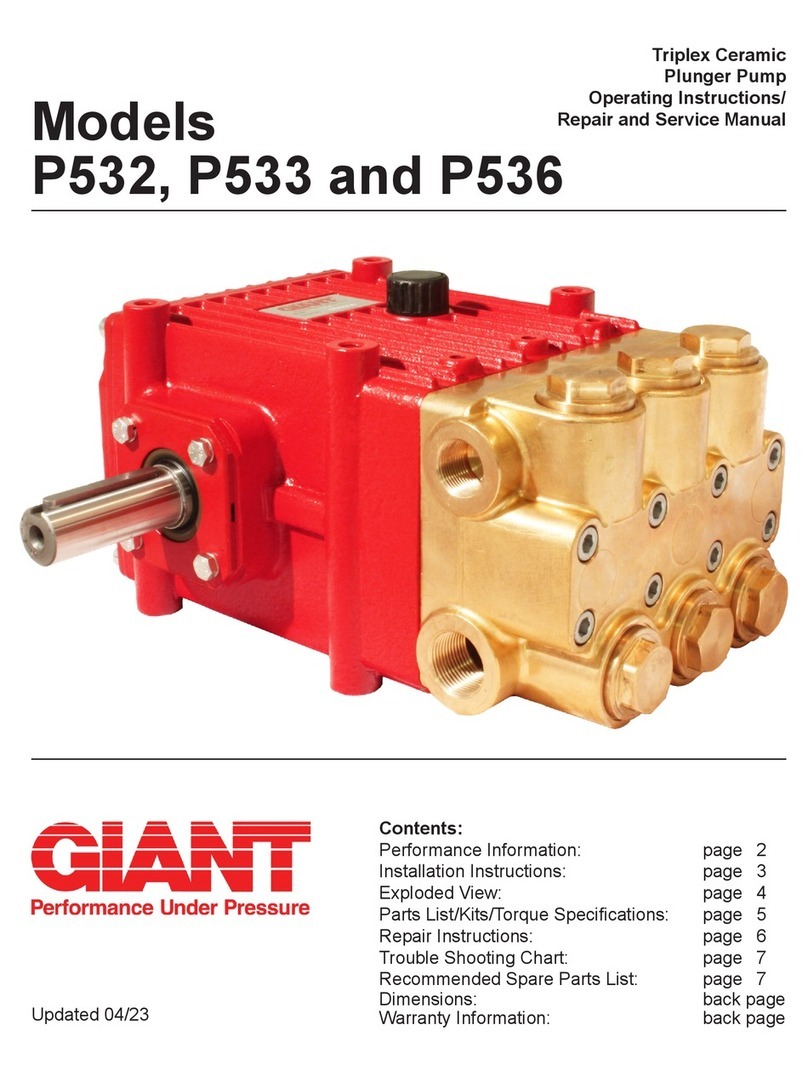
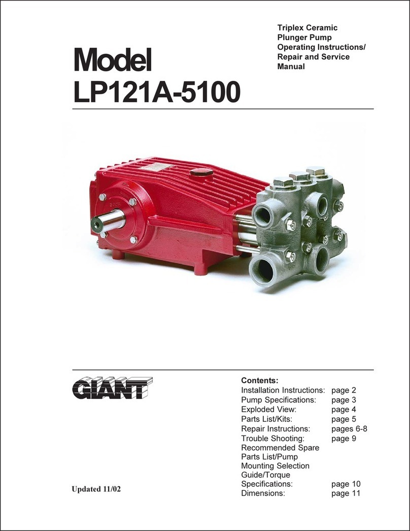
P400 Series -
18mm Versions
Triplex Ceramic
Plunger Pump
Operating Instructions/
Repair and Service Manual
Contents:
Installation Instructions: page 2
Pump Specications: pages 3
Exploded View: page 4
Parts List/Kits: page 5
Torque Specications: page 5
Repair Instructions: pages 6-7
Dimensions: back page
Warranty Information back page
Updated 05/20
For Models:
P435
P450
P451
P455B
P456B
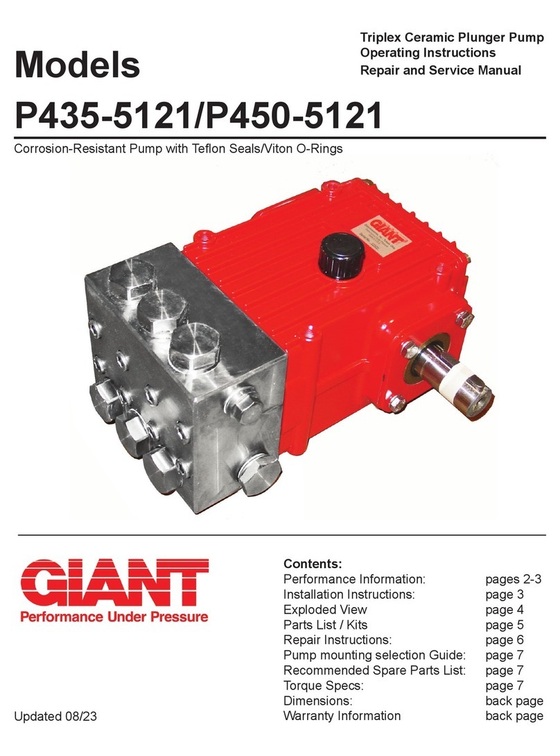
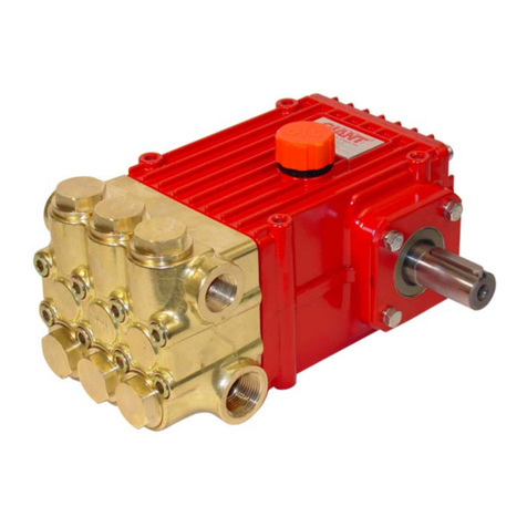
Brass Version Shown
2
Safety Rules
A safety valve is to be installed in accordance
with the guidelines for liquid spraying units so
that the admissible operating pressure cannot be
exceeded by more than 10%. Pump operation
without a safety vlave as well as any excess in
temperature or speed limits automatically voids
the warranty.
When the pump is in operation, the drive shaft
end and the coupling must be enclosed by a
protective cover or a coupling bell.
Pressure in the discharge line and pump must
be at zero before any maintenance to the pump
takes place. Shut o󰀨 suction line. Disconnect
fuses to ensure that the driving motor does not
get switched on accidentally. Make sure that all
parts on the pressure side of the unit are vented
before starting the pump. In order to prevent air,
or an air-water mixture being absorbed and to
prevent cavitation occurring, the pump NPSHR
(=suction head) and water temperature must be
respected.
Cavitation and/or compression of gases lead
to uncontrollable pressure kicks which can
ruin pump and unit parts and also be dan-
gerous to the operator or anyone standing
nearby.
Giant Plunger Pumps are suitable for pumping
clean water and other non-agressive or non-
abrasive media with a specic weight similar to
water.
Before pumping other liquids - especially
inammable, explosive and toxic media - the
pump manufacturer must be consulted with
regard to the resistance of the pump mate-
rial. It is the responsibility of the equipment
manufacturer and/or operator to ensure that
all pertinent safety regulations are ahered to.
INSTALLATION INSTRUCTIONS
Required NPSH refers to water (specic weight 1kg/
dm3) at maximum permissible pump revolutions.
Operation and Maintenance
Check oil level prior to starting to ensure trouble-free
water supply.
Important! If there is a danger of frost, the water
in the pump and in the pump ttings (particularly the
unloader valve) must be emptied. The second dis-
charge port cal also be used and the pump run “dry”
for 1-2 minutes for this purpose.
Oil amount: 30.4 ounces (0.9 liters). Only use ISO
VG 220 industrial gear oil (e.g. Aral Degol BG220)
or automobile gear oil SAE 90 GL4 (Giant p/n
01154).
Initial oil change after 50 operating hours and then
every 500 hours, after 1 year if used less. Caution
when operating in damp places or with high temper-
ature uctuations. Oil must be changed immediately
should condensate (frothy oil) occur in the gear box.
NPSH values must be observed.
Maximum input pressure 145 PSI (10 bar), maxi-
mum suction head -4.35 PSI (-0.3 bar). Make sure
that suction pulsation is su󰀩ciently dampened - wa-
ter column resonance must be avoided.
Important! If the pump is not used for a long period
of time, it is possible the seals (23) could become
hard or brittle thus causing the pump to leak when
put into operation.
If this is the case, we recommend these seals be
replaced every 4 years.
3
Consult the factory for special requirements that must be met if the
pump is to operate beyond one or more of the limits specied above.
Horsepower Ratings:
We recommend a 1.15 service factor be specied when selecting an electric motor as the power source.
To compute electric motor horsepower required, use the following formula: HP = (GPM X PSI) / 1450.
The formula to determine the horsepower required for a gas engine is: HP = (GPM X PSI) / 1150.
The formula to determine the horsepower required for a diesel engine is: HP = (GPM X PSI) / 1250.
For the Application of a Hydraulic Motor:
To Determine the Torque of a Hydraulic Motor -- (GPM x PSI x 36.77) / RPM = Torque (in-lbs)
Calculating RPM / GPM of Pump:
A pump must be connected to an electric motor or gas or diesel engine with the correct ratio of pulleys
and belts to attain the required speed and GPM. The use of a Variable Frequency Drive (VFD) may also
be used to control the RPM of a properly sized electric motor when variable ows are required.
(Max. Pump RPM / Rated Pump GPM) x Required Pump GPM = Required Pump RPM
To calculate a pulley diameter one (1) pulley diameter and the required pump RPM must be known:
(Pump RPM x Pump Pulley Diameter) / Motor RPM = Motor Pulley Diameter
(Motor RPM x Motor Pulley Diameter) / Pump RPM = Pump Pulley Diameter
Common Specications:
Inlet Pressure ......................145 PSI (10 Bar)
Crankshaft Diameter............1.1” (28mm)
Keyway Width......................8mm
Crankcase Oil Capacity.......30.4 . oz. (0.9 L)
Inlet Ports ............................(2) 3/4” or (2) 1/2" BSP*
Discharge Ports...................(2) 1/2” BSP
Shaft Rotation.....Top of Pulley Toward Fluid End
Materials Used for P400 Pumps:
Manifold
(P450/P451) ... Aluminum Bronze
(others) ........... Forged Brass
Plungers ......... Solid Ceramic Oxide
Valves ............. 316 Stainless Steel
Seals............... Nitrile with Fabric Reinforcing
Gear End ........ Aluminum
*1/2" BSP for P450/P451/P456 and
3/4" BSP for P435 and P455
PUMP SPECIFICATIONS - P400 - 18MM PUMPS
Max. Flow Max.
Pressure
Max.
Speed
Power
Required
Max.
Temp
Plunger
Diameter
Stroke Weight
Model GPM PSI RPM HP F in in lbs
P450 5.5 5100 1450 19.2 160 0.71 0.79 38.3
P455B 5.5 4350/5100+1450 16.5/19.2+160 0.71 0.79 38.3
P451 5.8 5100 1450 20.3 160 0.71 0.72 38.3
P456B 5.8 4350/5100+1725 17.4/20.3+160 0.71 0.72 38.3
P435 6.6 3625 1450 16.5 160 0.71 0.94 38.3
Max. Flow Max.
Pressure
Max.
Speed
Power
Required
Max.
Temp
Plunger
Diameter
Stroke Weight
Model L/min Bar RPM kW C mm mm kg
P450 20.8 350 1450 14.3 70 18 20 17.4
P455B 20.8 300/350+1450 12.3/14.3+70 18 20 17.4
P451 22.0 350 1450 15.1 70 18 18.2 17.4
P456B 22.0 300/350+1725 13.0/15.1+70 18 18.2 17.4
P435 25.0 250 1450 12.3 70 18 24 17.4
U.S. Measurements
Metric Measurements
+Continuous/Intermittent Duty
4
EXPLODED VIEW - P435/P450/P451/P455B/P456
5
ITEM PART DESCRIPTION QTY.
1 08377 Crankcase 1
2 08378 Oil Fill Plug with Gasket 1
3 06479 Crankcase cover 1
3A 07186 Oil Sight Glass w/ Gasket 1
4 08380 O-Ring 1
5 07109 Oil Drain Plug 1
5A 06015 O-Ring for Oil Drain Plug 1
5B 08092 Plug with Gasket 1
6 01010 Screw 4
6A 01011-0400 Spring Washer 4
7 04739 Bearing Cover Open 1
8 05291 Bearing Cover Closed 1
8A 05292 Shim 1-3
8B 05293 Shim (May not be present) 1
8C 05964 Shim 1-2
9 01016 O-Ring 2
10 07114 Screw with Washer 8
11 07459 Radial Shaft Seal 1
12 05350 Taper Roller Bearing 2
13 04741 Crankshaft (P435) 1
13 04740 Crankshaft (P450/P455B) 1
13 03173 Crankshaft (P451/P456) 1
13A 04742 Spacer Ring 1
14 08091 Fitting Key 1
15 08390 Connecting Rod Assembly 3
16 05484 Plunger Assy.(Items 16A-16H) 3
16A 05352 Plunger Base 3
16B 08397 Plunger Pipe 3
16D 08399 Tension Screw 3
16E 07023 O-Ring 3
ITEM PART DESCRIPTION QTY.
16F 07203 Backup Ring 3
16G 07258 Copper Washer 3
16H 06431 Oil Scraper 3
17 06790 Crosshead Pin 3
19 05444 Oil Seal 3
20 05534 Seal Case 3
21 07266 O-Ring 3
23 08477 V-Sleeve, 18mm 6
24 07929 Pressure Ring 3
25 08402 Weep Return Ring 3
26 05574 Manifold (P43/P455/P456) 1
26 08470 Manifold (P450/P451) 1
27A 05543 Valve Assembly (Items 27-31) 6
27 05541 Valve Seat 6
28 05542 Valve Plate 6
29 07906 Valve Spring 6
30 07907 Valve Spring Retainer 6
31 07770 O-Ring 6
32 05544 Plug (P435/P455/P456) 6
32 08406 Plug (P450/P451) 6
33 05545 O-Ring (P435/P455/P456) 6
33 07489 O-Ring (P450/P451) 6
34 08484 Cap Screw (P435/P455/P456) 8
34 08396 Cap Screw (P450/P451) 8
36 13434 Plug, 1/2" BSP (P435/P455/P456) 1
36 13434 Plug, 1/2" BSP (P450/P451) 2
36A 06272 Copper Washer (P435/P455/P456) 1
36A 06272 Copper Washer (P450/P451) 2
37 07703 Plug, 3/4" BSP (P435/P455/P456) 1
P435/P450/P451/P455B/P456 REPAIR KITS
Valve Assembly Kits
P435/P455/P456 - # 09644
Item Part # Description Qty
27A 05543 Valve Assembly, Complete 6
33 05545 O-Ring 6
P450/P451 - # 09770
Item Part # Description Qty
27A 05543 Valve Assembly, Complete 6
33 07489 O-Ring 6
Plunger Packing Kit - # 09141
Item Part# Description Qty
21 07266 O-Ring 3
23 08477 V-Sleeve 6
24 07929 Pressure Ring 3
Oil Seal Kit - #09641
Item Part # Description Qty
19 05444 Oil Seal 3
P435/P450/P451/P455B/P456 SPARE PARTS LIST
TORQUE & LUBRICATION SPECIFICATIONS - P435/P450/P451/P455B/P456
Position Item# Description U.S Metric
3A 07186 Oil Sight Glass (Loctite 5910) 106 in.-lbs. 12 Nm
5 07109 Oil Drain Plug 59 ft.-lbs. 80 Nm
5B 08092 Plug with Gasket 59 ft.-lbs. 80 Nm
6 01010 Screw 110 in.-lbs. 12.5 Nm
10 07114 Screw with Washer 132 in.-lbs. 15 Nm
15 08390 Screw with Washer 97 in.-lbs. 11 Nm
16D 08399 Tension Screw (Loctite 243) 247 in.-lbs. 28 Nm
32 05544/08406 Plug (Loctite 243) 125 ft.-lbs. 170 Nm
34 08396/08484 Cap Screw (Lightly Oil) 30 ft.-lbs. 40 Nm
6
REPAIR INSTRUCTIONS - P435/P450/P451/P455B/P456
 Note:Alwaystaketimetolubricateallmetalandnonmetalpartswithalightlmofoilbeforereassembly.Thisstepwill
ensurepropert,atthesametimeprotectingthepumpnonmetalparts(i.e.,theelastomers)fromcuttingandscoring.
1) With a socket wrench, remove
the three discharge valve
plugs and three inlet valve
plugs (32). Inspect the o-ring
(33) for wear and replace if
damaged.
2) Using needle nose pliers,
remove the inlet and discharge
valve assemblies (27A).
Note:It may become neccesary
to remove the valve seat (27)
from the valve casing using a
slidehammer.
3) By inserting a small screw-
driver between the valve
seat (27) and the valve
spring retainer (30), the
valve assembly can be
separated.
4) Remove the o-ring (31).
Inspect all parts for wear and
replace as necessary. Apply
one drop of loctite 243 to the
valve plugs (32) and tighten
to 125 ft. lbs. (170 Nm).
5) Use a 8mm allen wrench to
remove the 8 socket head
cap screws (34). Carefully
slide the valve casing (26)
out over the plungers.
6) Remove seal adaptors (20) and
weep return rings (25) from the
valve casing.
7) Remove the pressure rings
(24) and v-sleeves (23)
from the valve casing (26).
8) Remove the weep grooved
seal (23) out of the seal
adaptor (20). Check O-rings
(21).
IMPORTANT! The grooved
seal (23) on the high-pressure
side is to be tted carefully into
the valve casing (26) using a
screwdriver. Under no circum-
stances must the seal surface
in the valve casing or the seal
lip be damaged.
9) Check surfaces of plunger (16). Damaged surfaces cause accelerated seal wear.
Deposits of all kinds must be removed from the plungers.
IMPORTANT! Plunger surfaces are not to be damaged. If there are lime
deposits in the pump, care must be taken that the drip-return bore in parts (25)
and (26) ensure trouble-free drip-return.
7
10) If the plunger pipe (16B) is worn,
remove tension screw (16D) and
remove along with plunger pipe
(16B). Check and clean plunger
surface (16A), check oil scraper
(16H). Cover thread of tension
screw (16D) with a thin lm of
Loctite and tighten carefully to 247
in.-lbs. (28 Nm).
IMPORTANT! Care must be
taken that glue does not get
between the plunger pipe (16B)
and centring sleeve (16C). The
plunger pipe should not be
strained by eccentric tightening
of the tension screw or through
damage to front surface of
plunger, otherwise it is liable to
fracture.
11) After installation of high pressure seals (23), place seal adaptor (20)
with weep seals & pressure ring installed, weep return ring (25) and high
pressure weep return ring (24) over plungers. Slide valve casing over
plungers and seat rmly. Replace the 8 socket head cap screws (34)
and tighten to 30 ft.-lbs. (40 Nm) in a crossing pattern (as shown to the
right). 8
7
6
5
42
13
REPAIR INSTRUCTIONS - P435/P450/P451/P455B/P456
Gear End
If oil leaks where the plunger (16) extends from the crankcase (1), the oil seals (19) and plungers (16) must be
examined and replaced if necessary. Remove oil plug (5) and drain oil; remove crankcase cover (3). Remove
valve casing (26), and seal case (20). Then remove plunger pipes (16B) and oil scrapers (16H) as described
above.
IMPORTANT! Before removing connecting rods be aware of their position on the crankshaft so as to return them
to the same location and orientation when re-assembling.
Remove screws from connecting rods (15), separate the back connecting rod half from the crankshaft and the
front connecting rod half. The connecting rod halves must be kept as pairs - do not mix them up. Push connecting
rod shaft as far as possible into the crosshead guide. Remove screws (10) and pry bearing covers (7,8) o󰀨 gently
with a screwdriver.
Carefully remove crankshaft (13) by threading it through the connecting rods (15), making sure not to bend the
connecting rods. Remove and disassemble connecting rods and plungers (16) paying close attention not to dam-
age the plungers. Pry out oil seal (19) using a screwdriver. Examine plunger surfaces (16A) and replace if neces-
sary.
To re-assemble, rst press the oil seal (19) into the crankcase. Then insert connecting rods with plungers remem-
bering their original location. Thread in the crankshaft (13). Replace bearing cover (7) and o-ring (9) together
with the radial shaft seal (11) and roller bearing (12) and x in place with screws (10). Replace roller bearing (12),
bearing cover (8) and o-ring (9). Adjust the clearance by tting shims (8A) under the bearing cover as required
to ensure that the crankshaft (13) turns easily without play being felt. Finally, mount connecting rod halves on
crankshaft matching them with other half and tighten screws (15) to 97 in-lb (11 Nm). Replace crankcase cover
(3) and o-ring (4). When remounting the valve casing (26), tighten hexagon socket screws (34) to 30 ft.-lb (40
Nm).
To Move Crankshaft to Opposite Side
Remove the valve casing (26) and seal case (20). Then rotate the crankcase 180°. Interchange the oil plug ((5B)
with oil dipstick (2). Rotate the crankcase cover (3) 180°. Remount the valve casing together with the seal casing
and the seal adapters (20). Make sure that the seal adapters are rotated in order that the bores face down-
wards.
ContactGiantIndustriesforserviceschoolinformation.
Phone:(419)531-4600
GIANT INDUSTRIES, INC.
900 N. Westwood Ave., Toledo, Ohio 43607
PHONE (419) 531-4600 FAX (419) 531-6836
www.giantpumps.com
© Copyright 2020 Giant Industries, Inc.
05/20 P435_P450_P451_P455_P456.indd
P435/P450/P451/P455B/P456 Dimensions - in (mm)
GIANT INDUSTRIES LIMITED WARRANTY
Giant Industries, Inc. pumps and accessories are warranted by the manufacturer to be free from defects in
workmanship and material as follows:
1. Five (5) years from the date of shipment for all pumps used in portable pressure
washers with NON-SALINE, clean water applications.
2. Two (2) years from the date of shipment for Giant pumps used in car wash
applications.
3. One (1) year from the date of shipment for all other Giant industrial and consumer
pumps.
4. Six (6) months from the date of shipment for all rebuilt pumps
5. Ninety (90) days from the date of shipment for all Giant accessories.
This warranty is limited to repair or replacement of pumps and accessories of which the manufacturer’s
evaluation shows were defective at the time of shipment by the manufacturer. The following items are NOT
covered or will void the warranty:
1. Defects caused by negligence or fault of the buyer or third party.
2. Normal wear and tear to standard wear parts.
3. Use of repair parts other than those manufactured or authorized by Giant.
4. Improper use of the product as a component part.
5. Changes or modications made by the customer or third party.
6. The operation of pumps and or accessories exceeding the specications set forth
in the Operations Manuals provided by Giant Industries, Inc.
Liability under this warranty is on all non-wear parts and limited to the replacement or repair of those products
returned freight prepaid to Giant Industries which are deemed to be defective due to workmanship or failure of
material. A Returned Goods Authorization (R.G.A.) number and completed warranty evaluation form is required
prior to the return to Giant Industries of all products under warranty consideration. Call (419)-531-4600 or fax
(419)-531-6836 to obtain an R.G.A. number.
Repair or replacement of defective products as provided is the sole and exclusive remedy provided hereunder
and the MANUFACTURER SHALL NOT BE LIABLE FOR FURTHER LOSS, DAMAGES, OR EXPENSES,
INCLUDING INCIDENTAL AND CONSEQUENTIAL DAMAGES DIRECTLY OR INDIRECTLY ARISING FROM
THE SALE OR USE OF THIS PRODUCT.
THE LIMITED WARRANTY SET FORTH HEREIN IS IN LIEU OF ALL OTHER WARRANTIES OR
REPRESENTATION, EXPRESS OR IMPLIED, INCLUDING WITHOUT LIMITATION ANY WARRANTIES
OR MERCHANTABILITY OR FITNESS FOR A PARTICULAR PURPOSE AND ALL SUCH WARRANTIES
ARE HEREBY DISCLAIMED AND EXCLUDED BY THE MANUFACTURER.
WARNING: This product might contain a chemical known to the State of California to cause cancer,
and birth defects or other reproductive harm.
For more information go to www.P65Warnings.ca.gov

Other manuals for P435

1

This manual suits for next models

5

Other Giant Water Pump manuals

Giant LP460 User manual

Giant

Giant LP460 User manual

Giant P400 Series User manual

Giant

Giant P400 Series User manual

Giant P532 User manual

Giant

Giant P532 User manual

Giant LP250 User manual

Giant

Giant LP250 User manual

Giant SP100HT User manual

Giant

Giant SP100HT User manual

Giant GP7132 User manual

Giant

Giant GP7132 User manual

Giant P400 Series User manual

Giant

Giant P400 Series User manual

Giant GP8055-Brine User manual

Giant

Giant GP8055-Brine User manual

Giant P400-5100 Series User manual

Giant

Giant P400-5100 Series User manual

Giant P57 User manual

Giant

Giant P57 User manual

Giant LP122A Series Service manual

Giant

Giant LP122A Series Service manual

Giant CP460 User manual

Giant

Giant CP460 User manual

Giant Triplex Ceramic Plunger Pump LP350 User manual

Giant

Giant Triplex Ceramic Plunger Pump LP350 User manual

Giant GP5128GB Series Instruction Manual

Giant

Giant GP5128GB Series Instruction Manual

Giant LP121HT User manual

Giant

Giant LP121HT User manual

Giant P300 Series User manual

Giant

Giant P300 Series User manual

Giant P220-3000 User manual

Giant

Giant P220-3000 User manual

Giant P420A-5100 User manual

Giant

Giant P420A-5100 User manual

Giant GP7124A-4000 User manual

Giant

Giant GP7124A-4000 User manual

Giant P300 Series User manual

Giant

Giant P300 Series User manual

Giant P200 Series User manual

Giant

Giant P200 Series User manual

Giant LP250-5100HK User manual

Giant

Giant LP250-5100HK User manual

Giant P200A-5100 Series Repair and User manual

Giant

Giant P200A-5100 Series Repair and User manual

Giant LP200 User manual

Giant

Giant LP200 User manual

Popular Water Pump manuals by other brands

SPIDO JC-800-P2 Original operating instructions

SPIDO

SPIDO JC-800-P2 Original operating instructions

Pentair AURORA 3310 INSTRUCTION, INSTALLATION, MAINTENANCE AND REPAIR MANUAL

Pentair

Pentair AURORA 3310 INSTRUCTION, INSTALLATION, MAINTENANCE AND REPAIR MANUAL

CSF Inox CN Series:CN 1 Instructions for installation, operation and maintenance

CSF Inox

CSF Inox CN Series:CN 1 Instructions for installation, operation and maintenance

EMP WP29 installation manual

EMP

EMP WP29 installation manual

EINHELL GE-SP 4390 N-A LL ECO operating instructions

EINHELL

EINHELL GE-SP 4390 N-A LL ECO operating instructions

Annovi Reverberi AR202 specification

Annovi Reverberi

Annovi Reverberi AR202 specification

Franklin Electric Little Giant B-1000 Series manual

Franklin Electric

Franklin Electric Little Giant B-1000 Series manual

Graco SaniForce BV Series instructions

Graco

Graco SaniForce BV Series instructions

Homa Barracuda GRP Series Installation and operation instruction manual

Homa

Homa Barracuda GRP Series Installation and operation instruction manual

Debem MB Instructions for use and maintenance

Debem

Debem MB Instructions for use and maintenance

Grundfos CR Series Installation and operating instructions

Grundfos

Grundfos CR Series Installation and operating instructions

IML BIG DISCOVERY Installation and maintenance manual

IML

IML BIG DISCOVERY Installation and maintenance manual

Pfeiffer MVP 015-2 DC operating instructions

Pfeiffer

Pfeiffer MVP 015-2 DC operating instructions

Grundfos TPE Installation and operating instructions

Grundfos

Grundfos TPE Installation and operating instructions

FRC AUTOFOAM FSA015 manual

FRC

FRC AUTOFOAM FSA015 manual

King Canada 2" Gasoline Water Pump KCG-2PG Service manual

King Canada

King Canada 2" Gasoline Water Pump KCG-2PG Service manual

FLOJET G-57 Series Installation & operation instructions

FLOJET

FLOJET G-57 Series Installation & operation instructions

GÜDE JA 200 T 400 V Operation manual

GÜDE

GÜDE JA 200 T 400 V Operation manual

manuals.online logo
manuals.online logoBrands
  • About & Mission
  • Contact us
  • Privacy Policy
  • Terms and Conditions

Copyright 2025 Manuals.Online. All Rights Reserved.