GILBARCO VEEDER-ROOT Encore M04489K00X User manual

MDE-4288 Encore® USB Printer Kit M04489K00X • Installation Page 1
Introduction
This manual provides installation instructions for Kit M04489K00X for Encore®Pumps/
Dispensers. The Kit M04489K004 contains the printer parts and hardware required for
installation in an Encore 500 equipped with CRIND®Control Node 2. The Kit M04489K005
contains the printer parts and hardware required for installation in an Encore 500 equipped
with CRIND Control Node 1.
Required Reading
Before installing these kits, the installer must read, understand, and follow:
•This manual
•NFPA 30A, The Automotive and Marine Service Station Code
•NFPA 70, The National Electric Code
•Applicable federal, state and local codes and regulations
Failure to do so may adversely affect the safe use and operation of the equipment.
Note: This kit must be installed by a Gilbarco Authorized Service Contractor (ASC) to ensure
warranty.
Related Documents
The following documents are related to the installation of the USB Printer Kits M04489K00X.
Required Tools
The following tools are needed to install the Encore USB Printer Kits M04489K00X:
•1/4-inch nut driver (long nut driver or driver with extension)
•8-mm nut driver (long nut driver or driver with extension)
•Sharp knife
•Chamfer tool
Document Number Title GOLD®Library
MDE-3804 Encore and Eclipse®Series Start-Up/Service Manual Encore and Eclipse
MDE-3893 Encore/Eclipse Owners Manual Encore and Eclipse
PT-1936 Encore Illustrated Parts Manual Parts Manual
MDE-4288
Encore®USB Printer Kit M04489K00X
Installation
October 2004
Installation

Introduction
Page 2 MDE-4288 Encore® USB Printer Kit M04489K00X •October 2004
Parts List
The Encore USB Printer Kit M04489K004
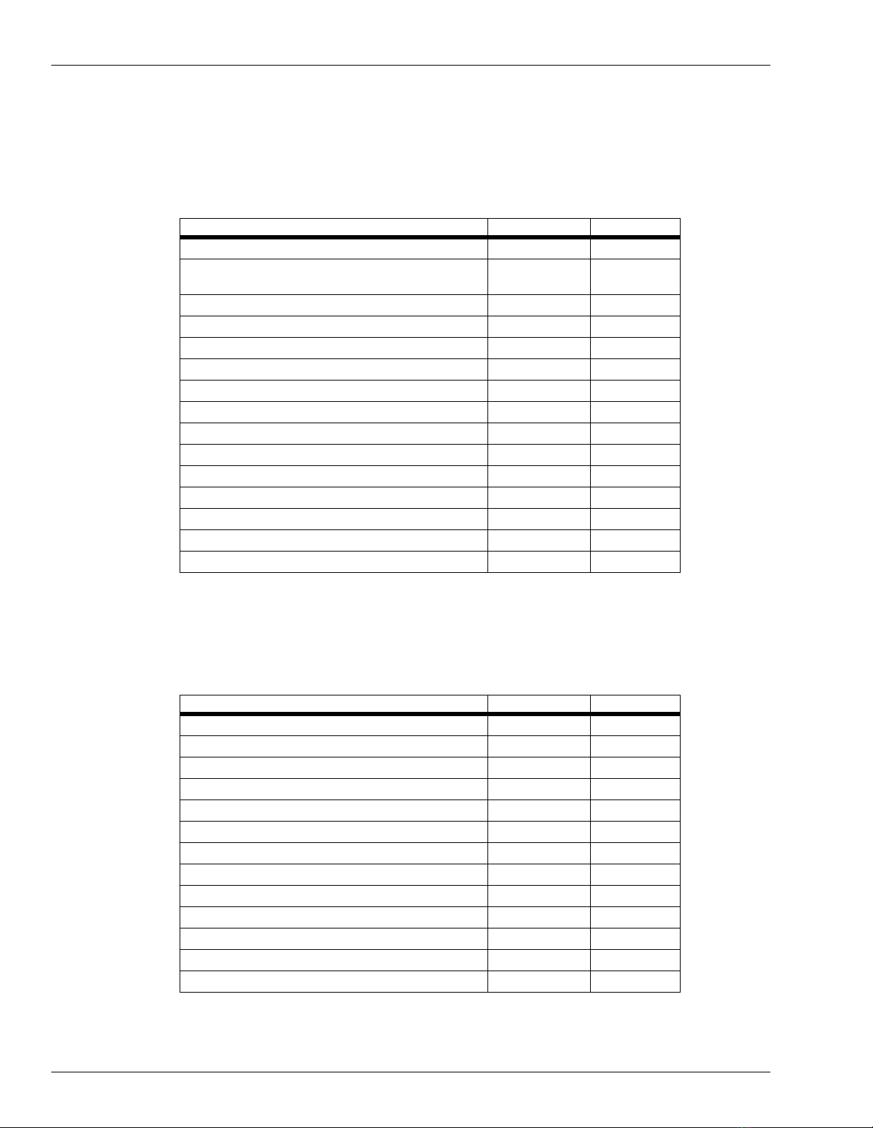
The following table lists the parts for the Encore USB Printer Kit M04489K004.
*The kit may contain either M03893A001 or M04915A001.
The Encore USB Printer Kit M04489K005
The following table lists the parts for the Encore USB Printer Kit M04489K005.
Description Part Number Quantity
Assembly, Printer Module M04119A001 2
PCA, SMART Connect™ M03893A001/
M04915A001* 1
Cable, USB 610mm M03695B004 1
Cable, USB 2135mm M03695B003 2
Cable, +24V Hengstler M04405A001 1
Cable, +24V Hengstler M04405A002 1
Bracket, Printer Bezel M03534B001 2
Gasket, Printer M00325B002 4
Cable, Ground Hengstler M04431A001 2
Kit, Speaker Retrofit M04435K001 2
Cable, Speaker/Wire M00636A001 1
Bracket, Speaker Retrofit M04432B001 1
Screw, Sel Tp Hex Hd 6-20X Q11677-24 1
Standoff, circuit board Q10651-02 4
Cutting Tool M04770B001 1
Description Part Number Quantity
Assembly, Printer Module M04119A001 2
PCA, CRIND Control Node 3 M04108A001 1
Cable, USB 2135mm M03695B003 2
Cable, +24V Hengstler M04405A001 1
Cable, +24V Hengstler M04405A002 1
Bracket, Printer Bezel M03534B001 2
Gasket, Printer M00325B002 4
Cable, Ground Hengstler M04431A001 2
Kit, Speaker Retrofit M04435K001 2
Cable, Speaker/Wire M00636A001 1
Bracket, Speaker Retrofit M04432B001 1
Screw, Sel Tp Hex Hd 6-20X Q11677-24 1
Cutting Tool M04770B001 1

MDE-4288 Encore®USB Printer Kit M04489K00X •October 2004 Page 3
Important Safety Information
This section introduces the hazards and safety precautions associated with installing,
inspecting, maintaining or servicing this product. Before performing any task on this product,
read this safety information and the applicable sections in this manual, where additional
hazards and safety precautions for your task will be found. Fire, explosion, electrical shock or
pressure release could occur and cause death or serious injury if these safe service procedures
are not followed.
Preliminary Precautions
You are working in a potentially dangerous environment of flammable fuels, vapors, and high
voltage or pressures. Only trained or authorized individuals knowledgeable in the related
procedures should install, inspect, maintain or service this equipment.
Emergency Total Electrical Shut-Off
The first and most important information you must know is how to stop all fuel flow to the
pump and island. Locate the switch or circuit breakers that shut-off all power to all fueling
equipment, dispensing devices, and submerged turbine pumps (STPs).
Evacuation and Barricading
Any procedures performed on or near the pump/dispenser (but not requiring accessing the
pump/dispenser or STPs) requires the following actions:
•An evacuation of all unauthorized persons and vehicles
•Using safety tape or cones as barricades to the effected units
Read the Manual
Read, understand and follow this manual and any other labels or related materials supplied
with this equipment. If you do not understand a procedure, call a Gilbarco Authorized Service
Contractor or call the Gilbarco Call Center at 1-800-800-7498. It is imperative to your safety
and the safety of others to understand the procedures before beginning work.
The EMERGENCY STOP, ALL STOP, and PUMP STOP buttons at the cashier’s
station WILL NOT shut off electrical power to the pump/dispenser.
This means that even if you activate these stops, fuel may continue to flow
uncontrolled.
You must use the TOTAL ELECTRICAL SHUT-OFF in the case of an emergency and
not only these cashier station “stops.”
WARNING
!

Important Safety Information
Page 4 MDE-4288 Encore®USB Printer Kit M04489K00X •October 2004
Follow the Regulations
There is applicable information in: NFPA 30A: Automotive and Marine Service Code; NFPA
70: National Electrical Code (NEC); OSHA regulations; and federal, state, and local codes
which must be followed. Failure to install, inspect, maintain or service this equipment in
accordance with these codes, regulations and standards may lead to legal citations with
penalties or affect the safe use and operation of the equipment.
Replacement Parts
Use only genuine Gilbarco replacement parts and retrofit kits on your pump/dispenser. Using
parts other than genuine Gilbarco replacement parts could create a safety hazard and violate
local regulations.
Safety Symbols and Warning Words
This section provides important information about warning symbols and boxes.
Alert Symbol
This safety alert symbol is used in this manual and on warning labels to alert you to a
precaution which must be followed to prevent potential personal safety hazards. Obey safety
directives that follow this symbol to avoid possible injury or death.
Signal Words
These signal words used in this manual and on warning labels tell you the seriousness of
particular safety hazards. The precautions that follow must be followed to prevent death,
injury or damage to the equipment
•DANGER - This signal word is used to alert you to a hazard to unsafe practice which will
result in death or serious injury
•WARNING - This alerts you to a hazard or unsafe practice that could result in death or
serious injury.
•CAUTION with Alert symbol - This signal word designates a hazard or unsafe practice
which may result in minor injury.
•CAUTION without Alert symbol - When used by itself, CAUTION designates a hazard
or unsafe practice which may result in property or equipment damage.
Prevent Explosions and Fires
Fuels and their vapors will become explosive if ignited. Spilled or leaking fuels cause vapors.
Even filling customer tanks will cause explosive vapors in the vicinity of dispenser or island.
No Open Flames
Open flames from matches, lighters, welding torches or other sources can ignite fuels
and their vapors.

MDE-4288 Encore®USB Printer Kit M04489K00X •October 2004 Page 5
Important Safety Information
No Sparks - No Smoking
Sparks from starting vehicles, starting or using power tools, burning cigarettes, cigars
or pipes can also ignite fuels and their vapors. Static electricity, including an electrostatic
charge on your body, can cause a spark sufficient to ignite fuels and their vapors. After getting
out of a vehicle, touch the metal of your vehicle to discharge any electrostatic charge before
you approach the dispenser island.
Working Alone
It is highly recommended that someone who is capable of rendering first aid be present during
servicing. Be familiar with Cardiopulmonary Resuscitation (CPR) methods if you are working
with or around high voltages. This information is available from the American Red Cross.
Always advise the station personnel about where you will be working, and caution them not to
activate power while you are working on the equipment. Use the OSHA tag out and lock out
procedures. If you are not familiar with this requirement, refer to information in the service
manual and OSHA documentation.
Working With Electricity Safely
Be sure to use safe and established practices in working with electrical devices. Poorly wired
devices may cause a fire, explosion or electrical shock.
•Be sure grounding connections are properly made.
•Make sure that sealing devices and compounds are in place.
•Be sure not to pinch wires when replacing covers
•Follow OSHA Lock-Out and Tag-Out requirements. Station employees and service
contractors need to understand and comply with this program completely to ensure safety
while the equipment is down.
Informing Emergency Personnel
Compile the following information for emergency personnel:
•Location of accident (e.g. address, front/back of building, etc.)
•Nature of accident (e.g. possible heart attack, run over by car, burns, etc.)
•Age of victim (e.g. baby, teenager, middle-age, elderly)
•Whether or not victim has received first aid (e.g. stopped bleeding by pressure, etc.)
•Whether or not victim has vomited (e.g. if swallowed or inhaled something, etc.)
IMPORTANT: Oxygen may be needed at scene if gasoline has been ingested or inhaled. Seek
medical advice immediately.

Installing the M04489K004/M04489K005 Kit
Page 6 MDE-4288 Encore®USB Printer Kit M04489K00X •October 2004
Installing the M04489K004/M04489K005 Kit
The following procedures describe installing the Encore USB Printer Kit M04489K004 or
M04489K005 in an Encore unit.
1Read all instructions before beginning installation.
2Observe and execute all safety precautions and procedures before, during and after
installation.
3Obtain permission from station Operator/Manager to remove pump/dispenser from service
and obtain key to the Customer Interface Module (CIM) door.
4Remove power from the pump/dispenser.
5Using the key, open the CIM doors on both sides of the unit.
Installing the USB Printers
1On side 1 of the unit, locate the existing (Fujitsu) printer on the CIM door (Figure 1).
Figure 1: The existing printer mounted on CIM door.
2Disconnect the power cable (Figure 1) from the printer and the LON Bus cable from both the
printer and from the M01785A001 Door Node 2.
3Move the M00605 Terminator from the new printer to the plug where LON Bus cable was just
disconnected from Door Node 2.
4Using the 8mm nut driver with extension, remove the three M5 printer mounting screws and
remove the printer. Save the screws for reuse later.
5Using the 1/4-inch nut driver, remove the four bracket mounting screws (two are visible on
Figure 1) and remove the printer bracket. Save the screws for reuse.
Existing
Fujitsu Printer
Bracket Mounting
Screws (Two of Four)
Power
Cable
LON Bus
Cable

MDE-4288 Encore®USB Printer Kit M04489K00X •October 2004 Page 7
Installing the M04489K004/M04489K005 Kit
6Using the Chamfer cutting tool, insert the tool through the printer mounting slot in the CIM
door. Hold the tool as shown in Figure 2 (also hold other end of tool) and shave off material
from the top of the slot until the blade of the tool fits vertically in the slot and a chamfer is cut
on the upper edge of the slot.
Figure 2: Cutting Chamfer in the Printer Slot
7Using a sharp instrument (such as a knife) or a file, trim out access material in the corners of
the slot as shown in Figure 3.
Figure 3: Cleaning Corners in the Printer Slot
8Clean up all material removed with the cutting tools.
Should fit flush after shaving

Installing the M04489K004/M04489K005 Kit
Page 8 MDE-4288 Encore®USB Printer Kit M04489K00X •October 2004
9Connect one end of the M04431A001 ground cable to the CIM door as shown in Figure 4 and
place the other end as shown to be connected to the printer bracket screw.
Figure 4: Ground Cable Connections at CIM Door.
10 Peal the protective cover from a M00325B002 printer gasket and stick to one side of the
M0353B001 printer bracket. Repeat the procedure and stick the gasket on the other side of
printer bracket (bracket is sandwiched between two gaskets - very important for good water
seal).
11 Using the screws saved in Step 4, mount the printer bracket (Figure 5) at the four screw holes
where old printer was mounted. Connect the ground cable to the upper left screw holding the
bracket. Do not overtighten screws as they may strip in the plastic CIM door.
Figure 5: USB Printer Mounting Bracket
*Ground cable not shown here (shown in Figure 4)
Ground Cable
Connection
M04431A001
Ground Cable
New USB printer
bracket
USB printer
mounting holes
Ground cable
connects here*

MDE-4288 Encore®USB Printer Kit M04489K00X •October 2004 Page 9
Installing the M04489K004/M04489K005 Kit
Figure 6: USB Printer Labelled Area
12 Mount the USB Printer by sliding the chute through the CIM door opening and aligning the
mounting holes in the printer with the mounting holes in the mounting bracket. The bracket is
designed to support the printer while you secure it in place.
13 Using a long nut driver (or nut driver with an extension) and two of the screws saved in Step 3,
start the mounting screws (Figure 7). Start both screws before tightening. You may need to
push down on the top of the printer and push the printer against the mounting bracket tightly to
get screws aligned and started into the mounting holes.
CAUTION
When handling the USB printer, do not apply pressure to the labelled area above the paper
insert slot on the upper portion of the printer (Figure 6). There are components under the label
that may be damaged. Grasp the printer on the sides.
Labelled area
(Do not apply pressure here)

Installing the M04489K004/M04489K005 Kit
Page 10 MDE-4288 Encore®USB Printer Kit M04489K00X •October 2004
Figure 7: Printer Mounting Screws
14 In the kit, locate the M04405A001 (for side A of dispenser) or M04405A002 (for side B of
dispenser) power cable and the M03695B003 USB cable.
15 Route the cables in the cable ties on the back of the CIM door as shown in Figure 8. Note the
type of plug on the ends of the cables and make sure the cables are oriented to place the plugs
in the proper location.
Figure 8: Cable Routing on Back of Main Door
Printer Mounting
Screw
Printer Mounting
Bracket

MDE-4288 Encore®USB Printer Kit M04489K00X •October 2004 Page 11
Installing the M04489K004/M04489K005 Kit
16 Connect the USB cable to the CRIND Control Node PCA, connect side 1 cable plug to P3120
(bottom) and side 2 cable plug to P3122 (top) as shown in Figure 9.
Note: If the unit is being updated from a CCN1 to CCN3, these connections can be made after
the CCN3 has been installed.
Figure 9: USB Printer Cable Connection to CRIND Control Node
17 Connect J4 jack of the power cable (side A) to P3502A of the M02774A001 power supply
PCA and J5 jack (side B) to P3502B cable jack J4 to Plug P4 and side 2 cable jack J5 to plug
P5.)
Figure 10: Connection to Power Supply
Side 2 Printer USB
Cable Plug
Side 1 Printer USB
Cable Plug
P3502B - side 2
printer connection
P3502A - side 1
printer connection

Installing the M04489K004/M04489K005 Kit
Page 12 MDE-4288 Encore®USB Printer Kit M04489K00X •October 2004
18 Connect the USB cable and power cable to the printer as shown in Figure 11. Be sure the
connector is oriented as shown (the red wires and latch facing the paper feed).
Figure 11: Cable Connections to USB Printer
19 Repeat steps 1 through 16 for side 2 of the unit.
Installing CRIND Control Node 3 Printed Circuit Assembly
Note: Perform this procedure only on units converting from CCN1 to CCN3
1IMPORTANT: Make a note of all connections to CRIND Control Node 1.
2Remove all connections to CRIND Control Node 1 and remove the PCA from the standoffs.
3Install the new CRIND Control Node 3 on the standoffs.
4Reconnect all the connections removed from CRIND Control Node 1 in Step 2 to CRIND
Control Node 3 following the notes taken when removed. Also, use the wiring block diagram
M04455 shown in Figure 16 to aid in reconnecting the wiring.
Installing SMART Connect Printed Circuit Assembly
Note: Perform this procedure only on units equipped with CCN2.
1In the kit, locate the M03893A001/M04915 SMART Connect Interface Board.
2Locate the four Q10651-02 circuit board standoffs in the kit.
Printer USB Cable
Printer Power Cable

MDE-4288 Encore®USB Printer Kit M04489K00X •October 2004 Page 13
Installing the M04489K004/M04489K005 Kit
3At the M00291A001 Mounting Bracket in the Encore unit (bracket shown in Figure 12), insert
the four standoffs into the mounting holes. The standoffs and card assembly are mounted on
the opposite side of the mounting bracket from the CRIND Control Node 2.
Figure 12: The M00291A001 Mounting Bracket Showing Mounting Holes
Place the M03893A001/M04915A001 Interface Board on the standoffs.
4Locate the M03695B004 cable.
Mounting holes for standoffs
M00291A001 Bracket
End B
End A

Installing the M04489K004/M04489K005 Kit
Page 14 MDE-4288 Encore®USB Printer Kit M04489K00X •October 2004
5Connect End B of the M03695B004 cable to P3620 on the M03893A001/M04915A001
SMART Connect Interface Board (M03893A001 shown in Figure 13).
Figure 13: The M03893A001 SMART Connect Interface Board
6Connect End A of the M03695B004 cable to P3120 on the M01753A001 CRIND Control
Node.
J3301
P3623
P3620 J3433/
P3433

MDE-4288 Encore®USB Printer Kit M04489K00X •October 2004 Page 15
Installing the M04489K004/M04489K005 Kit
Installing the Speaker Retrofit Kit
1In the M04489K004 or M04489K005 kit, locate the M04435K001 Speaker Retrofit Kit.
2On the back of the CIM door and to the left of the display (looking from back of door), mount
the M04432B001 speaker bracket and the M00636A001 Speaker and cable assembly. Secure
in place using the existing screws in the door. See Figure 14 for placement of bracket and
speaker.
Figure 14: Placement of Speaker Bracket and Speaker
3Connect the J2104 connector on the speaker and cable assembly to plug P2104 on the
M01785A001 Door Node 2 (Figure 15).
4Dress and secure the wires in existing cable ties.

Installing the M04489K004/M04489K005 Kit
Page 16 MDE-4288 Encore®USB Printer Kit M04489K00X •October 2004
Figure 15: M01785A001 Door Node 2
Restoring Power and Installing Printer Paper
1Restore power to the unit. A red LED should be blinking two times per second on the USB
printer. This means the printer is operational but out of paper.
2Load paper in both printers following instructions on the printer.
3Perform a printer test to verify that the printer is operational.The red LED should be blinking
one time per second indicating paper is loaded and communication is good.
P2104

MDE-4288 Encore®USB Printer Kit M04489K00X •October 2004 Page 17
Installing the M04489K004/M04489K005 Kit
Reprogramming the Unit
Note: Reprogramming is required only if the CRIND Control Node was replaced.
Laptop must be loaded with version V2.6.20 or higher of the Encore software.
1Connect the laptop to Jack 3111 on CRIND Control Node.
2Follow the procedures provided in MDE-3804, Encore and Eclipse Start-Up and Service
Manual to update the software at the Encore pump/dispenser.
Completing the Installation
3Remove from the site any equipment/materials that were removed from the pump/dispenser,
unused materials, protective material used during assembly, and safety equipment.
4Close and secure all unit doors.

Installing the M04489K004/M04489K005 Kit
Page 18 MDE-4288 Encore®USB Printer Kit M04489K00X •October 2004
Figure 16: Encore Block Diagram M04455 (Sheet 6)

MDE-4288 Encore®USB Printer Kit M04489K00X •October 2004 Page 19
Installing the M04489K004/M04489K005 Kit
Figure 17: Encore Block Diagram M04455 (Sheet 7)

Installing the M04489K004/M04489K005 Kit
© 2004 Gilbarco Inc.
7300 West Friendly Avenue •Post Office Box 22087
Greensboro, North Carolina 27420
Phone (336) 547-5000 •http://www.gilbarco.com •Printed in the U.S.A.
MDE-4288 Encore®USB Printer Kit M04489K00X •October 2004
CRIND®, Eclipse®, Encore®, and GOLD®are registered trademarks of Gilbarco Inc.
SMART Connect™is a trademark of Gilbarco Inc.
Table of contents