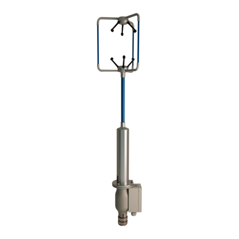
MetPak II and MetPak R User Manual
Last Change ©Gill Instruments Ltd
09 March, 2012 Page i
Contents
1. Introduction.........................................................................................................1
1.1 Principle of Operation...................................................................................................... 3
1.1.1 Wind Speed and Direction Sensor.....................................................................3
1.1.2 Radiation Shield................................................................................................ 4
1.1.3 Temperature and Relative Humidity Sensor with Dewpoint Output.................... 4
1.1.4 Barometric Pressure.......................................................................................... 4
1.2 Abbreviations.................................................................................................................. 5
1.3 Initial Test Guides........................................................................................................... 6
1.3.1 MetPak II (Part 1723-PK-100) ........................................................................... 6
1.3.2 MetPak II R (Part 1723-PK-150)........................................................................ 8
2. Installation........................................................................................................10
2.1 Pre-Installation Checks.................................................................................................10
2.1.1 Spare Parts..................................................................................................... 10
2.2 Installation..................................................................................................................... 11
2.2.1 Bench system test........................................................................................... 11
2.2.2 Equipment Required........................................................................................ 11
2.2.3 Cabling............................................................................................................11
2.2.4 Communication connections............................................................................16
2.2.5 Mounting MetPak II and MetPak II R............................................................... 20
3. Operation...........................................................................................................25
3.1 MetView........................................................................................................................ 25
3.1.1 Opening MetView............................................................................................ 25
3.1.2 Scanning for Devices....................................................................................... 26
3.1.3 The MetView Console ..................................................................................... 27
3.1.4 MetView Console Display Options...................................................................28
3.1.5 MetView Gauge Ranges and Graphs.............................................................. 29
3.1.6 Data logging....................................................................................................31
3.2 Configuring MetPak II/MetPak II R................................................................................ 34
3.2.1 Configuring MetPak II/MetPak II R using MetSet............................................. 35
3.2.2 MetSet Editing Screen..................................................................................... 37
3.2.3 Configuring using HyperTerminal.................................................................... 39
3.2.4 Configuring MetPak II/MetPak II R for NMEA Output......................................43
3.2.5 Configuring MetPak II/MetPak II R for SDI-12................................................. 44
3.2.6 SDI-12 Commands.......................................................................................... 44
3.2.7 Safe Mode.......................................................................................................47
