8/15
Alcatel Vacuum Technology France - User’s Manual AP/APN 2004
12/15
Alcatel Vacuum Technology France - User’s Manual AP/APN 2004
9/15
Alcatel Vacuum Technology France - User’s Manual AP/APN 2004 10/15
Alcatel Vacuum Technology France - User’s Manual AP/APN 2004 11/15
Alcatel Vacuum Technology France - User’s Manual AP/APN 2004
13/15
Alcatel Vacuum Technology France - User’s Manual AP/APN 2004 14/15
Alcatel Vacuum Technology France - User’s Manual AP/APN 2004 15/15
Alcatel Vacuum Technology France - User’s Manual AP/APN 2004
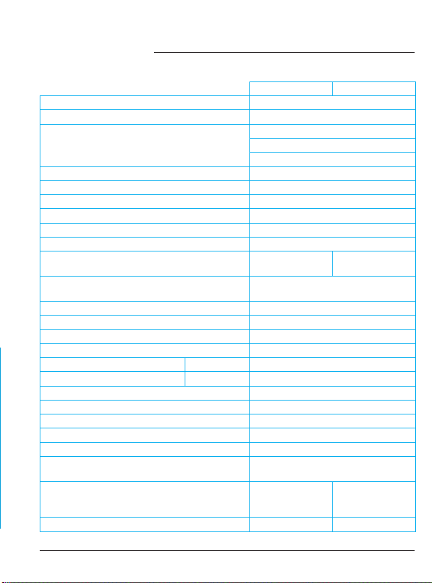
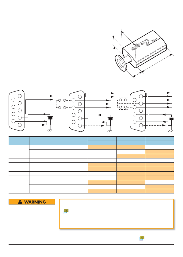
The analog output signal (0/10V) is available on Pins 1(+) and 8(–).
The analog signal can be converted to pressure according to the
formula:
P = 10(U–d) where : P= pressure, U= analog signal voltage,
d= constant.
Measurement limits: 8.5 V = 1000 mbar and 2.2 V = 5x10
–4
6- Operation (ctd)
Analog Signal output
0/10 V
AP 2004 - 0/10 V and
AP/APN 2004 0/10 V+SP
RS485 communication is available on the connector Pins 1(+)
and 8(–) .
Refer to the RS485 Communication Manual for details.
RS485 Signal output
(AP 2004 - RS485 + SP)
Note: For AP2004-RS485+SP models, the adjustments can also
be done with via link RS485 interface.
6- Operation (ctd)
Set points 1 and 2 are modified using the switch selector:
- To set up the mantissa, use the digits 1 to 9 directly.
- To set up the exponent value (from +6 to –9) use the values in
the table below:
- To set up the measurement units, use:
mbar = 2 , torr = 1 or Pascal = any other position.
Set Point set up
AP 2004 - 0/10 V + SP
APN 2004 - 0/10 V + SP
Switch
selector
ABCDEF0123456789
Exponent +6 +5 +4 +3 +2 +1 0 –1 –-2 –3 –4 –5 –6 –7 –8 –9
6- Operation (ctd)
Set Point set up (ctd)
AP/APN 2004 - 0/10 V+ SP
Set
the dial
Validate
with the SP SEL
button
Check
the confirmation
SP1 SP2
Initial state
1Start the process
2Set the dial to ‘5’ for the
mantissa of set point 1 (5x10+2)
3Set the dial to ‘E’ for the exponent
of Set point 1 (5x10+2)
(+2 = ‘E’ from the previous table)
4Set the dial to ‘8’ for the
mantissa of set point 2 (8x10⁻¹)
5
5) Set the dial to ‘1’ for the
exponent of set point 2 (8x10⁻¹)
(-1 = ‘1’ from the previous table)
6Set the dial to ‘2’ for mbar
(1 = Torr, any other setting = Pascal)
– End of process –
LED off
LED on steady
LED flashing
Follow this example to set up the set points (refer also to table
next page):
set point 1: 5 x 10+2 = 500 mbar
set point 2: 8 x 10–1 = 0.8 mbar
Example values
Note: For the AP2004-RS485+SP models, the set points are modified only via the RS485
interface. (refer to the RS485 Communication Manual)
The set point relay output has a fixed 10% hysteresis.
Set point output
AP 2004 - 0/10 V + SP
APN 2004 - 0/10 V + SP
AP 2004 - RS485 + SP
6- Operation (ctd)
Pressure Signal
Off Off
On On
Set Point Value
Relay Output
Hysteresis
+ 10 % of S. P. value
When removing this gauge from the vacuum system, do not touch
the inside of the connecting flange of the gauge or vacuum system
with bare hands. Fingerprints will increase outgassing in the gauge
and cause erroneous pressure readings
- Vent the vacuum system to atmospheric pressure.
- Turn off the power to the gauge.
- Remove the electrical connector.
- Remove the gauge from the vacuum system.
- Place a protective cap on the fitting to prevent foreign
substances from entering the gauge.
- If the gauge must be stored, we advise to keep it away from
heat, moisture an dust ( 4 p. 4).
8- Maintenance
Dirt and damages can impair the function of vacuum
components. Disregard can lead to an increase of out gassing in
the vacuum system and it may have negative effects on the vacuum
process itself. Keep the gauge clean.
Do not clean the measurement device except the connecting flange.
Only use denatured alcohol to clean the outside of the gauge.
- Small Philips screwdriver and an Ohmmeter.
Tools required
- The sensor and/or the electronics can be replaced. Proceed as
follows:
- Loosen the set screw without removing it (1)
- Pull out the sensor (2) as shown.
- Replace the sensor (2) or the electronic (3) as needed.
- Carefully align the holes in the electronics to the pins on the
sensor, then push the sensor into the electronics. Take care not to
bend the pins on the sensor. Secure the sensor to the electronics
with the set screw.
- Be sure to adjust the sensor after assembly ( 6 p. 9).
Sub-assembly
replacement
11 - Declaration of Conformity
10 - Decontamination and Product
Recycling
9- Return the Products
8- Maintenance (ctd)
If it is necessary to check the filament of the sensor, proceed as
follows:
- Remove the sensor from the electronics ( 8 p. 12),
- Using an ohmmeter, check the filament resistance,
- If the measured value is out of range, replace the sensor..
Checking the filament
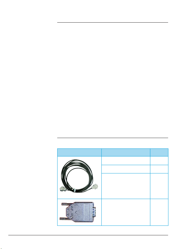
Item Description P/N
2
Sensor DN16 ISO KF AP2004 113043
Sensor DN16 CCF AP2004 113044
Sensor1/8 NPT AP 2004 113045
Sensor DN 16 ISO-KF APN 2004 115798
3
Electronics 0/10 V AP 2004 113192
Electronics 0/10 V + SP AP 2004 113193
Electronics RS485 + SP AP 2004 113194
Electronics 0/10 V + SP APN 2004 115799
Products that are not clearly declared as “free of harmful
substances“ are decontaminated at the expense of the customer.
Products not accompanied by a duly completed “Safety
Questionnaire“ are returned to the sender at his own expense.
Substances detrimental to the environment.
Products or parts thereof (mechanical and electriccomponents,
operating fluids etc.) can be detrimental to the environment. Dispose
of such substances in accordance with all relevant local regulations.
In compliance with Directive 2002/96/CE concerning the handling
of electrical and electronic equipment waste and Directive
2002/9/CE concerning restrictions on hazardous substances,
Adixen products that have reached the end of their service life must
be returned to the manufacturer for decontamination and reuse.
The manufacturer’s obligation to recover such equipment applies
only to complete items of equipment that have been neither
modified nor retrofitted and have used only spare parts sold by
Alcatel Vacuum Technology and including all their assemblies and
sub-assemblies.
This obligation does not include the cost of transporting the
product to a reprocessing centre, nor the cost of the service
which will be invoiced on to the customer.
All equipment returned to the Service Centre, must have a
properly filled in safety questionnaire. The questionnaire is
available separately, or on our Web site.
After disassembling the product, separate its components
according to the following criteria:
Contaminated components
Contaminated components (radioactive, toxic, caustic, or
biological hazard etc.) must be decontaminated in accordance
with the relevant local regulations, separated according to their
materials, and disposed of.
Other components
Such components must be separated according to their materials
and recycled.
Separating the
components
Unit Pa mbar Torr
d 3.5 5.5 5.62
mbar
For use with gasses other than Air, O2, N2, or CO, multiply the pressure reading by the
conversion factor from the table below: This formula is useful only for pressures under 1 mbar.
Pa
mbar
Torr
Measurement
signal U (V)
Pressure P
2.2
2.5 3.0 4.0 5.0 6.0 7.0 8.0
3.5 4.5 5.5 6.5 7.5 8.5
10–4
10–3
10–2
10–1
1
101
102
103
104
105
Parts on a vacuum processing system can be contaminated with
material that is detrimental to health and environment.
Before removing this gauge, confirm whether or not the gauge
is contaminated with any harmful gasses or vapors. If it is
contaminated with any harmful substances, be sure the gauge and
equipment are purged and cleaned thoroughly before removal of
the gauge.
Take the necessary precautions when handling contaminated parts,
refer to 9 p. 13.
7- Gauges Removal
Contaminated products (e.g. with radioactive, toxic, caustic
or microbiological hazard) can be detrimental to health and the
environment. Products returned to the manufacturer should be
cleaned and free of harmful substances. Be sure to follow the
shipping regulations of all involved countries and forwarding
companies and enclose a duly completed «Safety Questionnaire»
available on our web site before shipping any products back to the
manufacturer.
Contaminated parts.
Contaminated parts can be detrimental to health and the
environment. Before working on any parts, find out if they are
contaminated. Adhere to any relevant regulations and take the
necessary precautions when handling contaminated parts.
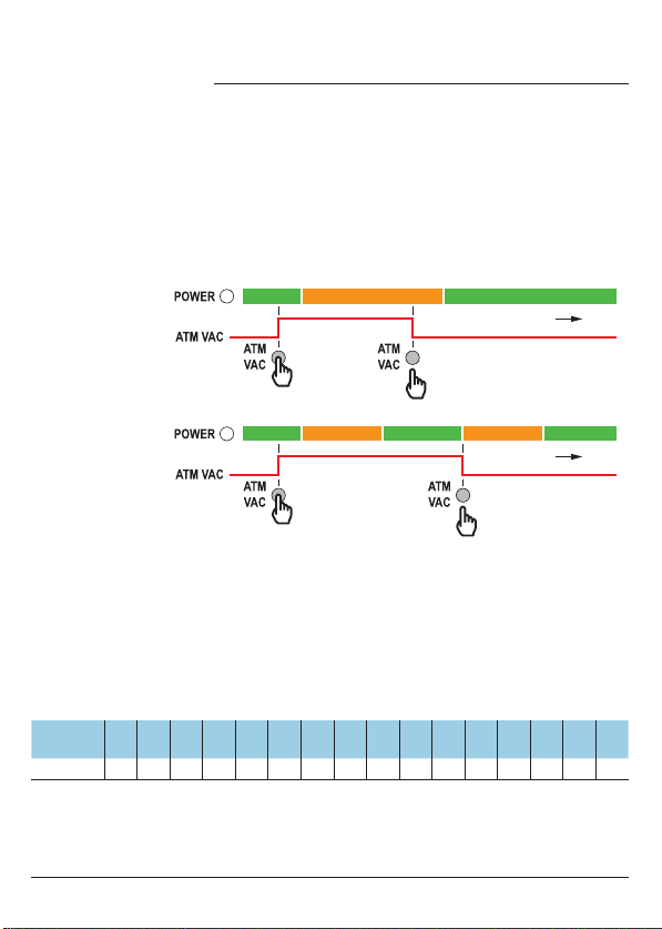
The gauge can be adjusted at two points, atmospheric pressure
(ATM) and at the low pressure limit of the gauge (VAC). The
gauge automatically determines whether the conditions are at
atmosphere or under low pressure (zero). Before adjustment, the
gauge must be mounted in the same orientation and conditions
it will be used in. It must be held in these conditions for at least
10 minutes before proceeding. To adjust the zero, be sure the
gauge current pressure is below 1 x 10⁻⁴ mbar (7.6 x 10⁻⁵ Torr).
Adjustment of the
gauge readings
Allow to restore the
ATM or VAC stored
value.
The desired value
becomes the ATM
stored value.
Note: The stored
VAC value can not
be changed.
Press
and hold Release
time
green greenorange
Press
and hold
green orange orangegreen green
Release the switch until you
reach the desired value
(500<ATM<1100 mbar or
380 Torr<ATM<830 Torr)
time
ATM or VAC adjustments
ATM stored value change
1
2
3
85 ΩAP
54 ΩAPN
Error Gauges AP/APN 2004
Power Led & Voltage (V)
Controller
Message Probable Error Action
AV 9.5 V red ErrHi Broken filament of Pirani Check Pirani filament
Replace sensor head
B* 8.582 ≤V < 9.5 V green Or If correct ATM/VAC
adjustment is not
possible or in case of
erractic measurements
=
sensor contaminated
Check sensor head
Replace sensor head
C* 2.199 V < 8.582 V green 1.2 +2
D* 0.5 V < 2.199 V green Ur
E0.2 V < 0.5 V red Err06 Electronic error Replace electronics
GV 0.2 V red ErrL0 Electronic error Replace electronics
Error catalog
(*) =minor error
degraded working of the gauge
Gas H2H2O CCl2F2He CO2Air, O2CO, N2Ne Ar Kr Xe
C 0.5 0.5 0.7 0.8 0.9 1.0 1.4 1.7 2.4 3.0