2GIOVENZANA INTERNATIONAL B.V. - MT-FGR1-EN / 28.06.2021 - Rev. 4
INTRODUCTION
Terms of use
Special conditions for a safe usage
GIOVENZANA INTERNATIONAL B.V.
Terms of use
Special conditions for a safe usage
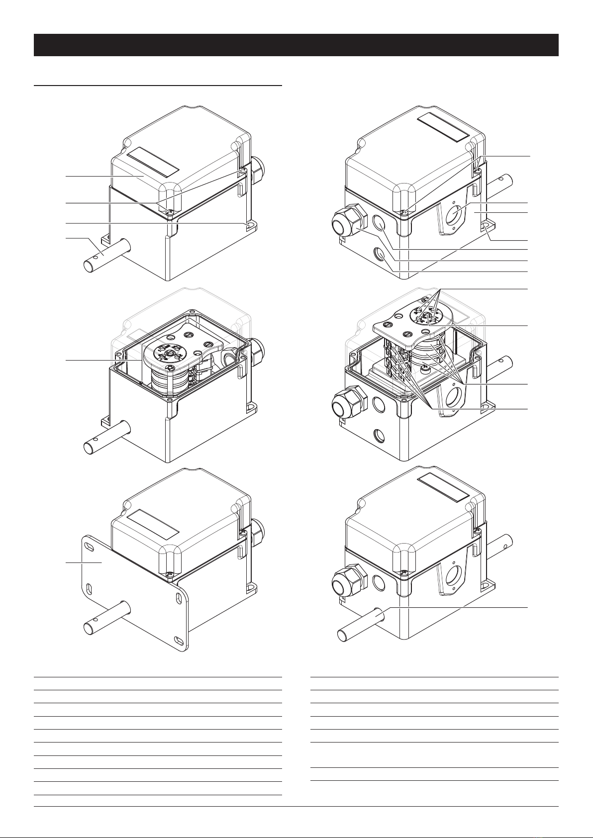
The FGR rotary gear limit switch is a device used to
control the number of turns or the rotation/direction
angle of industrial and building machines.
A typical application is the rolling shutter door,
overhead cranes or tackles etc. The unit, throught a
gear system and cams transmission, controls 2 or
more microswitches so, after a determined number of
revolutions, it can prepare the motor to start or stop run.
The microswitches have a calibration screw that
operates independently on each cam; so it can calibrate
the opening and closing of each micro according the
functional requirements needed.
The system gear transmission allows you to choose
different ratios with the main shaft.
The equipment must be installed only if it is completely
intact and unbroken. The product must be installed
according to the applicable code of practice, national
regulations and laws and / or international standards as
well as in compliance with the present instructions.
Do not change anything inside or outside the
equipment.
Low mechanical risk
The equipment is suitable for resisting impact energies
up to 4 J.
When impacts of energy are likely greater than 4 J,
additional mechanical protection is required around the
plastic case.
Potential electrostatic risk
The equipment is intended for fixed use and the user
must not frequently touch the equipment in service
(except for maintenance).
To avoid the potential electrostatic charge, it is
necessary to perform the following instructions during
the installation and service of the FGR:
• Do not install under direct air or other gas flow. If
these requirements cannot be met, additional external
direct flow protection is required.
• Install only when the relative humidity of the
environment is greater than 30% (stable, always or
for a long time) or in an environment with a humidity
control system.
• The metal parts of the casing must be connected
to the equipotential system in accordance with the
instructions in paragraph “Connection of earthing or
bonding conductors”.
• Do not rub the plastic cover insistently. If cleaning is
required (e.g. to remove dust) only manual operations
with wet materials are allowed.
Conditions
• The inner components (cam MFI micros, mounting
brackets, etc.) are mounted in order to guarantee the
type of protection.
• Any modification is forbidden.
• Do not remove any components or micro even if they
are not used.
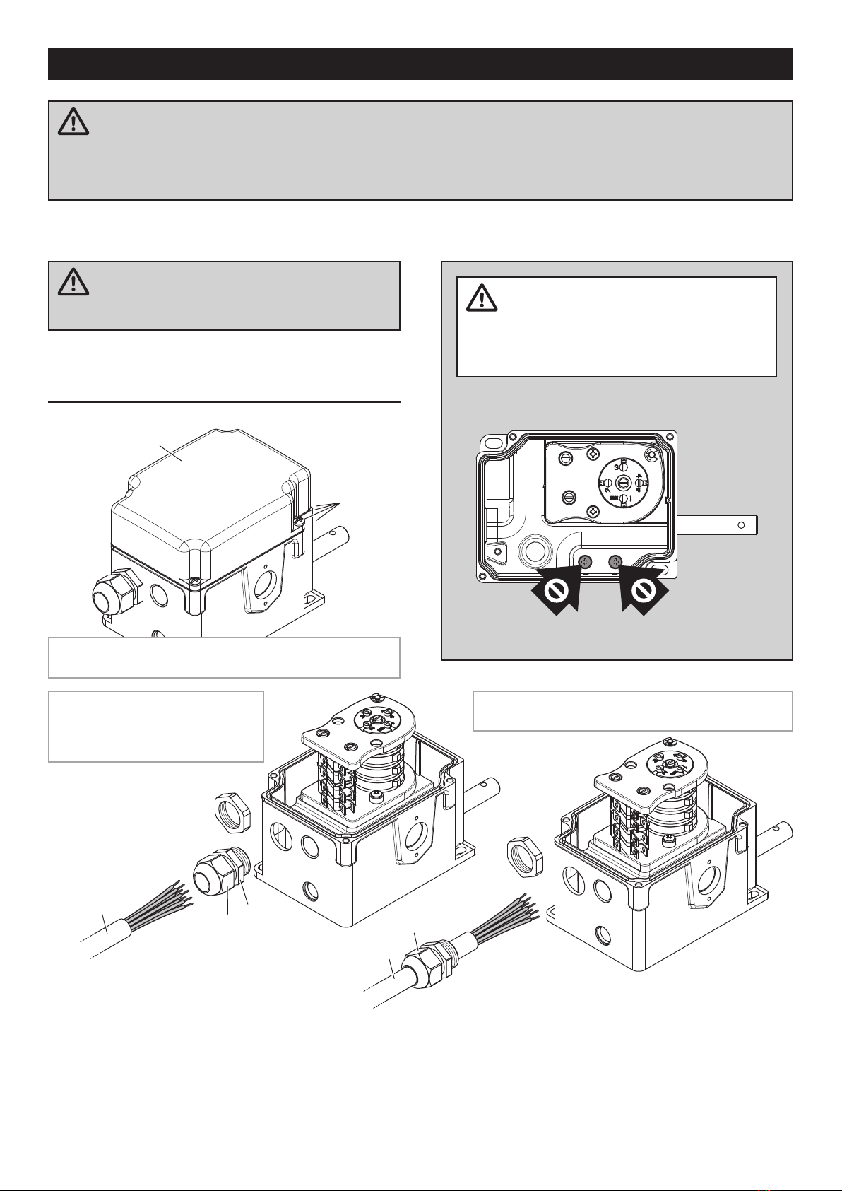
Types of protection
• Every screw shall be tightened with the tightening
torque according to this document, to maintain the
degree of protection IP.
• Additional holes and/or entries into enclosure are
forbidden, the only entries in the enclosure shall be
made by Giovenzana (see the information reported in
clause 1 of this document).
• The type of protection and minimum degree of
protection (IP code) of the entries into enclosure
or cable glands shall be in accordance with the
equipment marking.
• Any entry of the enclosure, the mounting of the entries
into enclosure or cable glands shall be carried out to
maintain the level of protection of the equipment.
Connection of earthing or bonding conductors
The equipment shall be earthed in accordance with the
relevant code of practice. The equipment is provided by
internal connection terminal for earthing.
If the reference standards applicable for the installation
require an external equipotential connection or these
become necessary for other reasons, connect the
equipotential conductor to the external earth terminal,
identified with the earthing symbol.
The conductors used for the earth and equipotential
connection must be equipped with an eye lug. Install
each conductor according to the following instructions:
• Place the eyelet in contact with the threaded hole of
the internal or external earth terminal, positioned on
the metal box.
• Place a Grover washer or non-loosening washer
between the eye lug and the clamp screw.
• Tighten the ground terminal screw with a tightening
torque of 1.7 N×m (15 lb×in). On the internal earth
screw add some threadlocker. Tightening the screw
ensures electrical continuity.
INTRODUCTION
GIOVENZANA INTERNATIONAL B.V.
Terms of use
Special conditions for a safe usage
The FGR rotary gear limit switch is a device used to
control the number of turns or the rotation/direction
angle of industrial and building machines.
A typical application is the rolling shutter door,
overhead cranes or tackles etc. The unit, throught a
gear system and cams transmission, controls 2 or
more microswitches so, after a determined number of
revolutions, it can prepare the motor to start or stop run.
The microswitches have a calibration screw that
operates independently on each cam; so it can calibrate
the opening and closing of each micro according the
functional requirements needed.
The system gear transmission allows you to choose
different ratios with the main shaft.
The equipment must be installed only if it is completely
intact and unbroken. The product must be installed
according to the applicable code of practice, national
regulations and laws and / or international standards as
well as in compliance with the present instructions.
Do not change anything inside or outside the
equipment.
Low mechanical risk
The equipment is suitable for resisting impact energies
up to 4 J.
When impacts of energy are likely greater than 4 J,
additional mechanical protection is required around the
plastic case.
Potential electrostatic risk
The equipment is intended for fixed use and the user
must not frequently touch the equipment in service
(except for maintenance).
To avoid the potential electrostatic charge, it is
necessary to perform the following instructions during
the installation and service of the FGR:
• Do not install under direct air or other gas flow. If
these requirements cannot be met, additional external
direct flow protection is required.
• Install only when the relative humidity of the
environment is greater than 30% (stable, always or
for a long time) or in an environment with a humidity
control system.
• The metal parts of the casing must be connected
to the equipotential system in accordance with the
instructions in paragraph “Connection of earthing or
bonding conductors”.
• Do not rub the plastic cover insistently. If cleaning is
required (e.g. to remove dust) only manual operations
with wet materials are allowed.
Conditions
• The inner components (cam MFI micros, mounting
brackets, etc.) are mounted in order to guarantee the
type of protection.
• Any modification is forbidden.
• Do not remove any components or micro even if they
are not used.
Types of protection
• Every screw shall be tightened with the tightening
torque according to this document, to maintain the
degree of protection IP.
• Additional holes and/or entries into enclosure are
forbidden, the only entries in the enclosure shall be
made by Giovenzana (see the information reported in
clause 1 of this document).
• The type of protection and minimum degree of
protection (IP code) of the entries into enclosure
or cable glands shall be in accordance with the
equipment marking.
• Any entry of the enclosure, the mounting of the entries
into enclosure or cable glands shall be carried out to
maintain the level of protection of the equipment.
Connection of earthing or bonding conductors
The equipment shall be earthed in accordance with the
relevant code of practice. The equipment is provided by
internal connection terminal for earthing.
If the reference standards applicable for the installation
require an external equipotential connection or these
become necessary for other reasons, connect the
equipotential conductor to the external earth terminal,
identified with the earthing symbol.
The conductors used for the earth and equipotential
connection must be equipped with an eye lug. Install
each conductor according to the following instructions:
• Place the eyelet in contact with the threaded hole of
the internal or external earth terminal, positioned on
the metal box.
• Place a Grover washer or non-loosening washer
between the eye lug and the clamp screw.
• Tighten the ground terminal screw with a tightening
torque of 1.7 N×m (15 lb×in). On the internal earth
screw add some threadlocker. Tightening the screw
ensures electrical continuity.
INTRODUCTION
GIOVENZANA INTERNATIONAL B.V.
Terms of use
Special conditions for a safe usage
The FGR rotary gear limit switch is a device used to
control the number of turns or the rotation/direction
angle of industrial and building machines.
A typical application is the rolling shutter door,
overhead cranes or tackles etc. The unit, throught a
gear system and cams transmission, controls 2 or
more microswitches so, after a determined number of
revolutions, it can prepare the motor to start or stop run.
The microswitches have a calibration screw that
operates independently on each cam; so it can calibrate
the opening and closing of each micro according the
functional requirements needed.
The system gear transmission allows you to choose
different ratios with the main shaft.
The equipment must be installed only if it is completely
intact and unbroken. The product must be installed
according to the applicable code of practice, national
regulations and laws and / or international standards as
well as in compliance with the present instructions.
Do not change anything inside or outside the
equipment.
Low mechanical risk
The equipment is suitable for resisting impact energies
up to 4 J.
When impacts of energy are likely greater than 4 J,
additional mechanical protection is required around the
plastic case.
Potential electrostatic risk
The equipment is intended for fixed use and the user
must not frequently touch the equipment in service
(except for maintenance).
To avoid the potential electrostatic charge, it is
necessary to perform the following instructions during
the installation and service of the FGR:
• Do not install under direct air or other gas flow. If
these requirements cannot be met, additional external
direct flow protection is required.
• Install only when the relative humidity of the
environment is greater than 30% (stable, always or
for a long time) or in an environment with a humidity
control system.
• The metal parts of the casing must be connected
to the equipotential system in accordance with the
instructions in paragraph “Connection of earthing or
bonding conductors”.
• Do not rub the plastic cover insistently. If cleaning is
required (e.g. to remove dust) only manual operations
with wet materials are allowed.
Conditions
•
The inner components (cam MFI micros, mounting
brackets, etc.) are mounted in order to guarantee the
type of protection.
Any modification is forbidden.
Do not remove any components or micro even if they
are not used.
Every screw shall be tightened with the tightening
torque according to this document, to maintain the
degree of protection IP.
Additional holes and/or entries into enclosure are
forbidden, the only entries in the enclosure shall be
made by Giovenzana (see the information reported in
clause 1 of this document).
The type of protection and minimum degree of
protection (IP code) of the entries into enclosure
or cable glands shall be in accordance with the
equipment marking.
Any entry of the enclosure, the mounting of the entries
into enclosure or cable glands shall be carried out to
maintain the level of protection of the equipment.
Connection of earthing or bonding conductors
The equipment shall be earthed in accordance with the
relevant code of practice. The equipment is provided by
internal connection terminal for earthing.
If the reference standards applicable for the installation
require an external equipotential connection or these
become necessary for other reasons, connect the
equipotential conductor to the external earth terminal,
identified with the earthing symbol.
The conductors used for the earth and equipotential
connection must be equipped with an eye lug. Install
each conductor according to the following instructions:
• Place the eyelet in contact with the threaded hole of
the internal or external earth terminal, positioned on
the metal box.
• Place a Grover washer or non-loosening washer
between the eye lug and the clamp screw.
• Tighten the ground terminal screw with a tightening
torque of 1.7 N×m (15 lb×in). On the internal earth
screw add some threadlocker. Tightening the screw
ensures electrical continuity.
INTRODUCTION
GIOVENZANA INTERNATIONAL B.V.
Microswitch technical data
Operating temperature -25 ... +85°C
Minimum life expectancy mechanical
electrical
one million of cycles
half million of cycles
Rated thermal current Ith 8 A
Rated insulation voltage Ui 250 V
Rated impulse withstand voltage Uimp 1500 V
Rated operating current le resistive load
inductive load
8 A - 250 V
3 A - 250 V
Pollution degree 2
Protection against electric shock class II
Terminals
The microswitches installed can have one of the three types of terminals illustrated below:
6.3×0.8 faston screws M3 for wire 1.5 mm² screws M3 for wire 1.5 mm²
with plate protection