manuals.online logo
Brands
  1. Home
  2. •
  3. Brands
  4. •
  5. 3One data
  6. •
  7. Switch
  8. •
  9. 3One data ICS5556 Series User manual

3One data ICS5556 Series User manual

ICS5556 Series
Modular Layer 3 Ethernet Switch
Quick Installation Guide
3onedata Co., Ltd.
Address: 3/B, Zone 1, Baiwangxin High Technology
Industrial Park, Xili, Nanshan District,
Shenzhen
Website: www.3onedata.com
Tel: +86 0755-26702688
Fax: +86 0755-26703485
【Package Checklist】
Please check the integrity of package and accessories
while first using the switch.
1. Modular switch
2. AC power line ×2
3. Quick installation guide
4. Foot pad ×4
5. CD (manual / network management tool)
6. Mounting lug ×2
7. Debugging cable for Console port
8. Warranty card
9. Certificate
If any of these items are damaged or lost, please contact
our company or dealers, we will solve it ASAP.
【Product Overview】
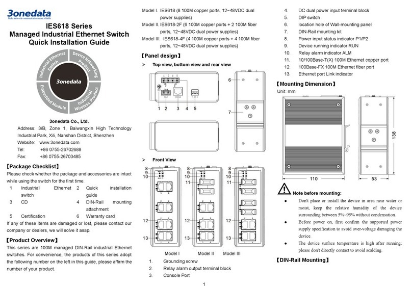
This series of products are modular layer 3 Ethernet
switches. The complete machine includes frame and 4
board cards, and supports 8-port full Gigabit SFP and 8-port
full Gigabit RJ45 board cards. The models of the complete
machine, frame and board cards are as follows.
Model I. (Complete machine) ICS5556-24GT24GS8XS-
2P220 (24 Gigabit copper ports + 24 Gigabit SFP
slots + 8 10Gigabit SFP+, 100~240VAC
redundant power supply)
Model II. (Frame) ICS5556-MAIN-2P220 (8 10Gigabit
SFP+, 100~240VAC redundant power supply)
Model III. (Board card) ICS5556-IM-12GT (12 Gigabit
copper ports)
Model IV. (Board card) ICS5556-IM-12GS (12 Gigabit SFP
slots)
【Panel Design】
Frame-Front view
Frame-Rear view
Board card-Front view
Model II
Model III
Complete machine-Front view
Model IV
1. Running indicator (RUN)
2. Alarm indicator (ALM)
3. Power supply indicator (PWR1-PWR2)
4. Board card slot (1-4)
5. Restore default settings(RESET)
6. USB interface
7. CONSOLE port
8. MANAGER port
9. MANAGER indicator
10. 10Gigabit Ethernet port indicator (X1-X8)
11. 1000/10GBase-X SFP+ slot (X1-X8)
12. Lugs
13. Power supply module1
14. Power input socket with switch
15. Grounding screw
16. Power supply module2
17. Power supply handle
18. Gigabit Ethernet interface indicator (G1-G12)
19. 10/100/1000Base-T(X) Gigabit copper port (G1-G12)
20. 100/1000Base-X Gigabit SFP slot (G1-G12)
Notes:
No. 17 in the Frame-Rear view is the power supply handle, which
is only used for plugging in power and not for moving the device.
【Mounting Dimension】
Unit: mm
Notice Before Mounting:
Don't place or install the device in area near water or
moist, keep the relative humidity of the device
surrounding between 5%~95% without condensation.
Before power on, first confirm the supported power
supply specification to avoid over-voltage damaging
the device.
The device surface temperature is high after running;
please don't directly contact to avoid scalding.
【Rack-mounting】
Step 1 Select the device mounting position and ensure
enough mounting size is reserved.
Step 2 Put the device on the plane plate of the rack, and
install the left and right lugs on the rack with 4
screws.
Step 3 Check and confirm the product is mounted firmly
on the rack, mounting ends.
【Disassembling Device】
Step 1 Power off the device.
Step 2 Unscrew the fixed mounting lug screw on the
rack.
Step 3 Shift out the device from rack, disassembling
ends.
Notice before power on:
Power ON operation: First insert the power supply
terminal block into the device power supply interface,
then plug the power supply plug contact and power on.
Power switch “—” means power ON, “O” means
power OFF.
Power OFF operation: First, put the powers switch to
the "O" side and then disconnect the power supply.
Finally disconnect the connector between the device
and the power cord. Please notice the operation order
above.
【Power Supply Connection】
The device frame provides two power modules,
adopts AC power socket with switch, and
supports Power 1 and Power 2 inputs. The
series of device supports redundant power
supply, two power supply can work at the same time. The
device will still run non-stop when one power supply fails.
AC power supply range: 100~240VAC.
【RESET Button】
RESET button can be used to reboot the device
and restore factory defaults. The operation is as
follows: press the button for 1~2s and release it, and the
device will restart automatically; Press and hold the RESET
button for 3~4s and release it, and the device will
automatically restore the factory defaults.
【USB Port Connection】
The device frame provides one Type-A USB2.0
interface, which can be connected to an
external USB flash disk to import or back up the switch
configuration file.
【Console Port Connection】
The device frames provides 1 program debugging
port based on RS-232 serial port which can
conduct device CLI command management after
connecting to PC. The interface adopts RJ45 port, the RJ45
pin definition as follows:
Pin No.
2
3
5
Definition
TXD
RXD
GND
【MANAGER Connection】
The device frame provides one MANAGER port,
that is Gigabit Ethernet interface, for device
network management.
【Checking LED Indicator】
The device frame provides LED indicators to monitor the
device working status with a comprehensive simplified
troubleshooting; the function of each LED is described in
the table as below:
LED
Indicate
Description
PWR1-
PWR2
ON Power supply is running
normally
OFF Power supply is disconnected
or running abnormally
ALM
ON Power supply or port link has
alarm
OFF Power supply and port link
have no alarm
RUN
ON Device is not started or
abnormal
Blinking The device is running
normally
OFF The device is powered off or
the device is abnormal.
G1-G12,
X1-X8,
MANAGER
ON Port has established a valid
network connection
Blinking Port is in a network
communication status
OFF Port hasn’t established valid
network connection.
【Logging in to WEB Interface】
This device supports WEB management and configuration.
Computer can access the device via Ethernet interface. The
way of logging in to device’s configuration interface via IE
browser is shown as below:
Step 1 Configure the IP addresses of computer and the
device to the same network segment, and the
network between them can be mutually accessed
Step 2 Enter device’s IP address in the address bar of
the computer browser.
Step 3 Enter device’s username and password in the
login window as shown below.
Step 4 Click “Login” button to login to the WEB interface
of the device.
Note:
The default IP address of the device is
“192.168.1.254”.
The default username and password of the device are
“admin123”.
If the user name or password is lost, user can restore it
to factory settings via restoring factory setting button
or management software; all modified configurations
will be cleared after restoring to factory settings, so
please backup configuration file in advance.
Please refer to user manual for specific configuration
method of logging in to WEB interface and other
configurations about network management function.
【Specification】
Panel
10Gigabit SFP+ 1000/10GBase-X self-
adaptive
SFP+ slot
Gigabit SFP 100/1000Base-X self-adaptive
SFP+ slot
Gigabit copper port 10/100/1000Base-T(X) self-
adaptive RJ45 port, support
full/half duplex, MDI/MDI-X self-
adaption
CONSOLE port CLI command management
port (RS-232), RJ45
MANAGER port 10/100/1000Base-T(X) self-
adaptive RJ45 port, support
full/half duplex, MDI/MDI-X self-
adaption
Indicator
Power indicator, alarm
indicator, running status
indicator, interface indicator
Switch Property
Backplane bandwidth
256G
Packet buffer size
32Mbit
MAC Address Table
96K
Power Supply
Input power supply
100~240VAC redundant power
supply
Access terminal block Single-
phase socket with
rocker switch
Power Consumption
Full-load
(high temperature)
≤ 60W@220VAC (all board
cards and the complete
machine are copper ports)
≤ 90W@220VAC (all board
cards and the complete
machine are fiber ports)
Working Environment
Working temperature
-40
~
60
℃
Storage temperature
-40
~
60℃
Working humidity
5%
~
95% (no condensation)
Protection grade
IP30(metal shell)

Other 3One data Switch manuals

3One data IES5028G-4GS-8GC User manual

3One data

3One data IES5028G-4GS-8GC User manual

3One data PS5010G-2GS-8PoE User manual

3One data

3One data PS5010G-2GS-8PoE User manual

3One data IES5024 Series User manual

3One data

3One data IES5024 Series User manual

3One data TNS5800-8GP16GT-P24VDC User manual

3One data

3One data TNS5800-8GP16GT-P24VDC User manual

3One data IES206G-2GS User manual

3One data

3One data IES206G-2GS User manual

3One data IES6100PN-8T-2LV User manual

3One data

3One data IES6100PN-8T-2LV User manual

3One data IES7110-2GS Series User manual

3One data

3One data IES7110-2GS Series User manual

3One data IES615-2DI(3IN1) Series User manual

3One data

3One data IES615-2DI(3IN1) Series User manual

3One data IES6200-PN-16T4GS-2P48 User manual

3One data

3One data IES6200-PN-16T4GS-2P48 User manual

3One data TNS5800 Series User manual

3One data

3One data TNS5800 Series User manual

3One data TNS5800D Series User manual

3One data

3One data TNS5800D Series User manual

3One data IES6300-8GHP2GS2HS-2P48-360W User manual

3One data

3One data IES6300-8GHP2GS2HS-2P48-360W User manual

3One data ICS5428 Series User manual

3One data

3One data ICS5428 Series User manual

3One data ICS5530 Series User manual

3One data

3One data ICS5530 Series User manual

3One data IES2010 Series User manual

3One data

3One data IES2010 Series User manual

3One data SW4485I User manual

3One data

3One data SW4485I User manual

3One data TNS5800D Series User manual

3One data

3One data TNS5800D Series User manual

3One data IES2305 Series User manual

3One data

3One data IES2305 Series User manual

3One data TNS5800D User manual

3One data

3One data TNS5800D User manual

3One data IPS7110 Series User manual

3One data

3One data IPS7110 Series User manual

3One data IES2312-8GT2GS2HS-2P48 User manual

3One data

3One data IES2312-8GT2GS2HS-2P48 User manual

3One data IES2005 User manual

3One data

3One data IES2005 User manual

3One data MES600 Series User manual

3One data

3One data MES600 Series User manual

3One data TNS5000D Series User manual

3One data

3One data TNS5000D Series User manual

Popular Switch manuals by other brands

Zte ZXR10 5900 Series Product description

Zte

Zte ZXR10 5900 Series Product description

Hawking CS164 user manual

Hawking

Hawking CS164 user manual

Escient ZONE LS102 installation guide

Escient

Escient ZONE LS102 installation guide

Moxa Technologies EDS-408A user manual

Moxa Technologies

Moxa Technologies EDS-408A user manual

TP-Link JetStream T1500-28PCT user guide

TP-Link

TP-Link JetStream T1500-28PCT user guide

Renesas Emulation Pod for M30240 Group MCUs... user manual

Renesas

Renesas Emulation Pod for M30240 Group MCUs... user manual

ADTRAN NetVanta 1638 Hardware installation guide

ADTRAN

ADTRAN NetVanta 1638 Hardware installation guide

Alloy POEFE8TV2 user manual

Alloy

Alloy POEFE8TV2 user manual

3Com Baseline 2226-PWR Plus user guide

3Com

3Com Baseline 2226-PWR Plus user guide

Extreme Networks 200 Series Installation and user guide

Extreme Networks

Extreme Networks 200 Series Installation and user guide

Leviton Decora L5614 Installation

Leviton

Leviton Decora L5614 Installation

HP V1810-48G Quick setup guide

HP

HP V1810-48G Quick setup guide

Longshine LCS-883R-SW2402 user manual

Longshine

Longshine LCS-883R-SW2402 user manual

Cisco 6500 - Catalyst Series 10 Gigabit EN Interface Module... Installation note

Cisco

Cisco 6500 - Catalyst Series 10 Gigabit EN Interface Module... Installation note

Wulian WL-SFB-S Series user manual

Wulian

Wulian WL-SFB-S Series user manual

Emulex Model 375 Quick install card

Emulex

Emulex Model 375 Quick install card

EUCHNER TQ2-1211SG024-5000 operating instructions

EUCHNER

EUCHNER TQ2-1211SG024-5000 operating instructions

TRENDnet TEG-S240TX - DATA SHEETS Specifications

TRENDnet

TRENDnet TEG-S240TX - DATA SHEETS Specifications

manuals.online logo
manuals.online logoBrands
  • About & Mission
  • Contact us
  • Privacy Policy
  • Terms and Conditions

Copyright 2025 Manuals.Online. All Rights Reserved.