Gira Plus User manual
DALI gateway Plus
DALI gateway Plus
Order no.: 2180 00
Operating instructions
1 Safety instructions
Electrical devices may only be mounted and connected by electrically skilled persons.
Serious injuries, fire or property damage possible. Please read and follow manual fully.
Danger of electric shock. Always disconnect before carrying out work on the device or load. In
so doing, take all the circuit breakers into account, which support dangerous voltages to the
device and or load.
Danger of electric shock. Device is not suitable for disconnection from supply voltage.
The DALI control voltage is a functional extra-low voltage (FELV). On installing, ensure safe
isolation between KNX and DALI.
These instructions are an integral part of the product, and must remain with the end customer.
2 Function
System information
This device is a product of the KNX system and complies with the KNX directives. Detailed tech-
nical knowledge obtained in KNX training courses is a prerequisite to proper understanding.
The function of this device depends upon the software. Detailed information on loadable soft-
ware and attainable functionality as well as the software itself can be obtained from the manu-
facturer´s product database.
Planning, installation and commissioning of the device are carried out with the aid of KNX-certi-
fied software. Full functionality with KNX commissioning software version ETS3.0f onwards.
Intended use
– Controlling of luminaires and other applications with DALI operating device in KNX install-
ations e.g. electronic ballast
– Installation on DIN rail according to EN 60715 in distribution boxes
Product characteristics
– Control of up to 64 DALI devices in up to 32 groups
– Individual, group or central addressing
– Suitable for operation in emergency lighting systems
– 16 light scenes
– Effect control for dynamic lighting effects or colour games
– Read out DALI device state via KNX, e.g. brightness or luminaire error
– Manual operation of the DALI groups
– Restraint
– Feedback of switching state and brightness value in bus and manual mode
– Collective feedback
– Central switching function
– Disabling function for each DALI group
– Separate ON and OFF delay
– Staircase lighting timer with run-on time
– Corridor function: when combined with motion detectors, reduced continuous lighting, if
no motion is detected
– Online or offline project design of the DALI devices with ETS plug-in
1 / 7
32587022 10867792 15.06.2020

DALI gateway Plus
– Short circuit protection
– Surge protection
– Overload protection
– Operating hours counter
– Signal of the global switching status of the DALI devices, e.g. to switch off the mains
voltage of the DALI devices to avoid standby losses
– An individual DALI device can be exchanged during operation without software.
– With device generation I06 or higher: DALI-2 certified.
Delivery state: construction site mode, the DALI groups can be operated using button
field. All DALI devices are controlled jointly.
3 Operation
See illustration of the button field (Figure 1).
Figure1
(1) Button c – Manual operation
(2) LED c – On: Continuous manual mode active
(3) Button ON/n switch on or increase brightness
(4) LED ON/n On: DALI device or group switched on, brightness 1...100 %
(5) Button OFF/o switch off or reduce brightness
(6) LED OFF/o On: DALI device or group switched off, brightness 0 %
(7) Button ALL OFF – Switch off all DALI devices
(8) Display of DALI number (1…64)
(8a) Display of the DALI group
(8b) Display of the individual DALI device
If the display shows (8) bc (Broadcast operation), the device is not programmed or set to
master control in the KNX configuration. All DALI devices are then controlled jointly.
In operation with the button field the device distinguishes between a short and a long press.
– Short: Pressing for less than 1 second
– Long: Pressing for between 1 and 5 seconds
Switching on the temporary manual control
Operation using the button field is programmed and not disabled.
■ Press the c (1) button briefly.
Display (8) shows 01 or bc, LED c (2) remains off.
2 / 7
32587022 10867792 15.06.2020
DALI gateway Plus
After 5 seconds without a button-press, the device returns automatically to bus mode.
Switching on/off the permanent manual mode
Operation using the button field is programmed and not disabled.
■ Press the c (1) button for at least 5 seconds.
LED c (2) is illuminated, display (8) shows 01 or bc, permanent manual mode is
switched on.
- or in case of repeated actuation -
LED c (2) is off, display (8) is off, bus mode is switched on.
Operating DALI devices
The device is in continuous or short-term manual mode.
■ Press c (1) button briefly as many times as necessary until the display (8) shows the de-
sired DALI number.
■ Operate output with ON/n (3) button or OFF/o (5) button.
Short: switch on/off.
Long: dim brighter/darker.
Release: Stop dimming.
The LEDs ON/n (4) and OFF/o (6) indicate the status.
The display (8) shows first the numbers of the available DALI groups (8a), followed by the
individual addresses of the DALI devices (8b).
Switch off all DALI devices
The device is in continuous manual mode.
■ Press the ALL OFF button (7).
Disabling/enabling individual DALI devices or groups
The device is in continuous manual mode.
■ Press c (1) button briefly as many times as necessary until the display (8) shows the de-
sired DALI number.
■ Press the buttons ON/n (3) and OFF/o (5) simultaneously for at least 5 seconds.
The selected DALI number flashes in the display (8).
DALI device or group is blocked.
- or in case of repeated actuation -
The display (8) no longer flashes.
DALI device or group is enabled.
■ Activate bus mode (see section Switching on/off the permanent manual mode).
DALI devices blocked via manual operation can be operated in manual mode.
4 Information for electrically skilled persons
4.1 Fitting and electrical connection
DANGER!
Mortal danger of electric shock.
Disconnect the device. Cover up live parts.
Fitting the device
■ Mount device on DIN rail.
3 / 7
32587022 10867792 15.06.2020

DALI gateway Plus
Connecting the device
Control cable: appropriate type, cross-section and routing for the specifications for 250 V
cables. DALI and mains voltage wires can be run together in a cable, e.g. NYM 5x1.5 mm².
■ The DALI control voltage is a functional extra-low voltage (FELV). When performing in-
stallation, perform the installation in such a way that when an area is disconnected the
lines carrying both the DALI and also the mains voltage are disconnected.
■ If multiple circuit breakers supply dangerous voltages to the device or load, couple the
miniature circuit breakers or label them with a warning, to ensure disconnection is guaran-
teed.
■ DALI participants from some manufacturers have expanded functions and can e.g. be
controlled via mains voltage on the DALI connection. When existing DALI installations are
refitted, remove all corresponding operator controls.
■ Connect device as shown in the connection example (Figure 2).
Figure2
■ Attach the cover cap to the bus cable connection as protection against hazardous
voltages.
If the display (8) shows Er (error), an installation fault occurred that causes mains voltage
to reach the DALI cable. In this case disconnect the device and and the DALI devices
from mains voltage and disconnect bus voltage. Correct installation.
Operation in emergency lighting systems
The device can be used in decentrally-powered or in centrally-powered emergency lighting sys-
tems.
In decentrally-powered emergency light systems, emergency luminaires with individual batteries
and special DALI devices are used.
Observe the number of DALI devices in the emergency luminaires used.
The statutory and standard specifications vary from country to country. In any event, the
user / technical planner must check whether the specific specifications are observed.
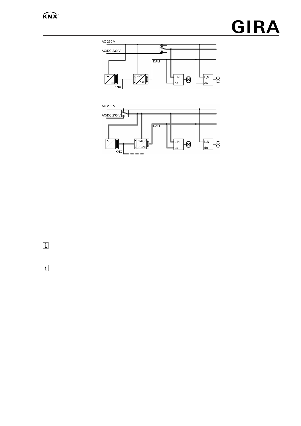
Emergency lighting systems with a central safety supply are required in buildings larger than
2000 m². Depending on the scope of functions of the system, only the emergency luminaires
are supplied by the central safety supply (figure 4), or the KNX system and DALI gateway are
also supplied (figure 5). In the latter case, in emergency operation, the DALI gateway can trans-
mit the appropriate fault messages to a central system and other DALI gateways in the system.
4 / 7
32587022 10867792 15.06.2020
DALI gateway Plus
Figure3: Emergency luminaires supplied through a central safety supply
Figure4: Emergency luminaires, KNX system and DALI gateway supplied through a central
safety supply
4.2 Commissioning
Load physical address and application program
■ Switch on mains voltage.
■ Switch on the bus voltage.
■ Press the programming button.
The programming LED lights up.
■ Load physical address and application program using the ETS.
■ Commission DALI system using commissioning software.
For more detailed information on commissioning of the DALI system, see the technical
product information for this device.
■ Load application program with the ETS.
No programming is possible if no mains voltage is connected.
5 Appendix
5.1 Technical data
Supply
Rated voltage AC 110 ... 240 V ~
Mains frequency 50 / 60 Hz
Rated voltage DC 110 ... 240 V
Power loss max. 3 W
Ambient conditions
Ambient temperature -5 ... +45 °C
Storage/transport temperature -25 ... +70 °C
DALI
Rated voltage DALI DC 16 V (typ.)
Output current DALI typ. 128 mA, max. 250 mA for short periods
5 / 7
32587022 10867792 15.06.2020

DALI gateway Plus
Number of DALI subscribers max. 64
DALI transmission rate 1.2 kBit/s
DALI protocol EN 62386
Cable type Sheathed cable 230 V, e,g. NYM
DALI cable length
with Ø 1.5 mm² max. 300 m
with Ø 1.0 mm² max. 238 m
with Ø 0.75 mm² max. 174 m
with Ø 0.5 mm² max. 116 m
Housing
Fitting width 72 mm / 4 module
Connection of power supply and DALI
Connection mode Screw terminal
single stranded 0.5 ... 4 mm²
Finely stranded without conductor sleeve 0.5 ... 4 mm²
Finely stranded with conductor sleeve 0.5 ... 2.5 mm²
KNX
KNX medium TP 256
Commissioning mode S-mode
Rated voltage KNX DC 21 ... 32 V SELV
Current consumption KNX 4.5 ... 5.0 mA
Connection type for bus device connection terminal
5.2 Troubleshooting
Indication shows "Er", connected DALI devices have no function, no operation possible
Cause: Mains voltage on DALI cable.
Installation error. Disconnect device and connected DALI devices from mains voltage and
disconnect bus voltage. Correct installation.
Indication shows "bc" in manual mode, control of individual luminaires not possible.
Cause: The device has not been programmed or is programmed to "Broadcast".
Check the device status. If necessary, program the device and put DALI system into oper-
ation.
Individual DALI devices have no function
Cause 1: Load is defective, e.g. lamp.
Exchange load.
Cause 2: DALI device is defective.
Exchange defective device.
Switch on voltage.
Press c and ALL OFF buttons together for at least 10 seconds.
The device detects the exchanges DALI device and loads in the necessary data. The dis-
play (4) shows LE.
Simultaneous exchange of multiple DALI devices is only possible with commissioning
software and project data.
6 / 7
32587022 10867792 15.06.2020

DALI gateway Plus
None of the DALI groups can be operated.
Cause 1: All DALI groups disabled via bus or manual operation.
Cancel disabling.
Cause 2: Continuous manual mode switched on.
Deactivating permanent manual control.
Cause 3: Application software has been stopped, programming LED is flashing.
Perform reset: Disconnect device from bus, switch on again after approx. 5 seconds.
Cause 4: Application software missing or faulty.
Check programming and correct.
5.3 Warranty
The warranty is provided in accordance with statutory requirements via the specialist trade.
Please submit or send faulty devices postage paid together with an error description to your re-
sponsible salesperson (specialist trade/installation company/electrical specialist trade). They will
forward the devices to the Gira Service Center.
Gira
Giersiepen GmbH & Co. KG
Elektro-Installations-
Systeme
Industriegebiet Mermbach
Dahlienstraße
42477 Radevormwald
Postfach 12 20
42461 Radevormwald
Deutschland
Tel +49(0)21 95 - 602-0
Fax +49(0)21 95 - 602-191
www.gira.de
7 / 7
32587022 10867792 15.06.2020
This manual suits for next models
1
Table of contents
Other Gira Gateway manuals


Popular Gateway manuals by other brands


Ruckus Wireless
Ruckus Wireless Virtual SmartZone High Scale reference guide

RBH Access Technologies
RBH Access Technologies Axiom III PC-100 Technical bulletin

AT&T
AT&T AT&T Wireless Home Phone Base user guide

MitraStar
MitraStar DSL-100HNU-T1 v3 user guide

Patton
Patton SmartNode 4740 Series user manual

Portech
Portech MT-350 Mobile Trunk Operation manual


