PROCEDURE DI INSTALLAZIONE
PROCEDURES OF INSTALLATION
S003.C ST •2¥2
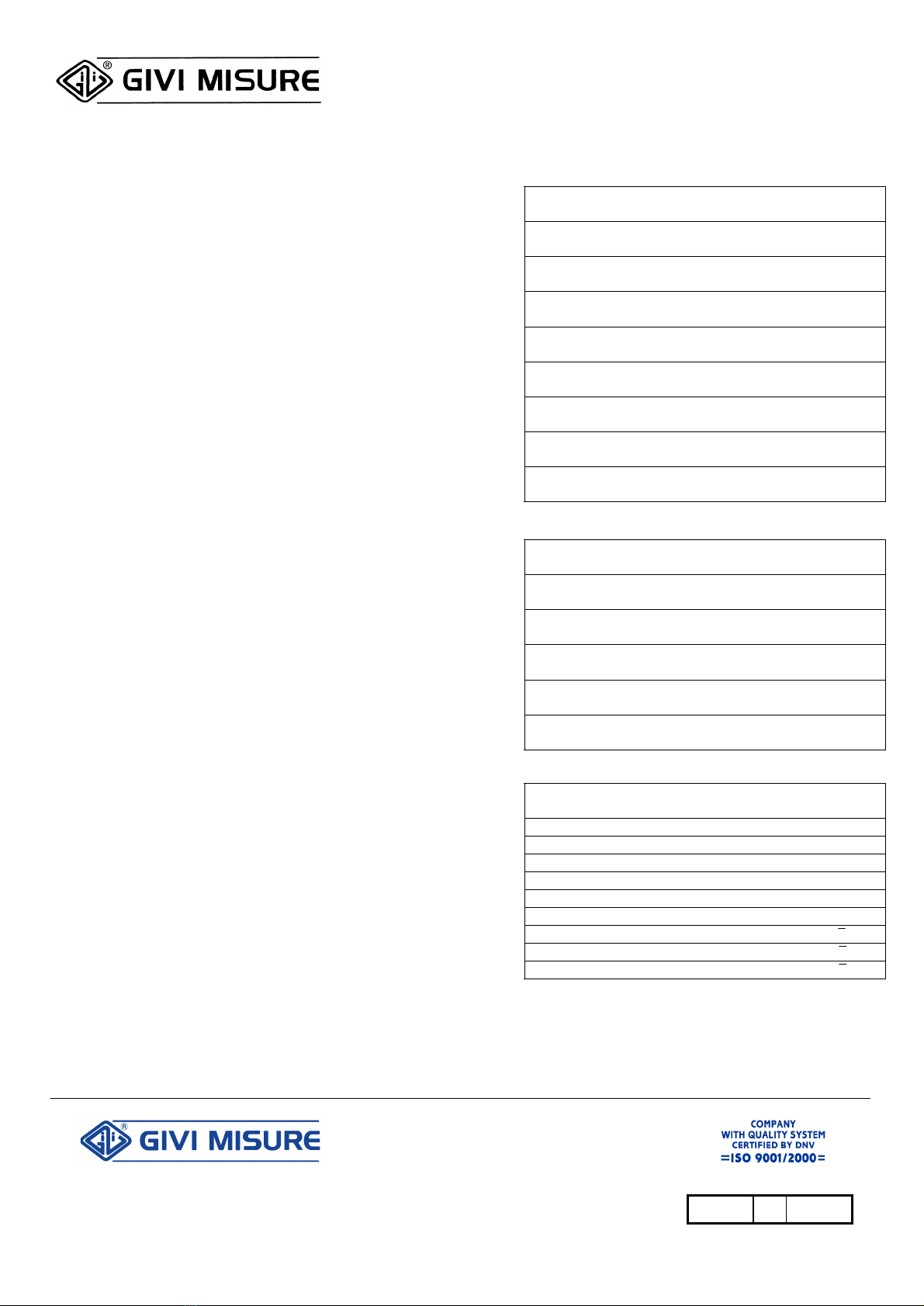
CARATTERISTICHE MECCANICHE / MECHANICAL FEATURES
PASSO RETICOLO µm 400 40 20
GRATING PITCH µm
GRADO DI ACCURATEZZA µm/m ±10 ±5 ±3/5
ACCURACY GRADE µm/m
ESPANSIONE TERMICA 10,6x10⁻⁶ °C-1
THERMAL EXPANSION T rif.=20° C ±0,1 °C
MAX VELOCITA’ m/min 120 80 60
MAX SPEED m/min
MAX ACCELERAZIONE 40 m/s2
MAX ACCELERATION
MAX RESISTENZA ALL’AVANZ. <= 4 N (0.4 Kgf)
MAX RESISTANCE TO FEED
PROTEZIONE A NORME IP 53 EN 60529
PROTECTION
TEMPERATURA ESERCIZIO 0 ÷50°C
OPERATING TEMPERATURE Umidità relativa 20 ÷80%
TEMPERATURA MAGAZZINO -20°C ÷70°C
STORAGE TEMPERATURE
CARATTERISTICHE ELETTRICHE / ELECTRICAL FEATURES
SENSORI -EMETTITORI Fototransistor –Led
SENSOR -EMITTERS Phototransistor –Led
ALIMENTAZIONE 5V dc oppure –or
POWER SUPPLY 12V dc ±5%
ASSORBIMENTO Tipico –Tipical
CURRENT CONSUMPTION 65 mA (5VQ/5VL)
USCITA SEGNALI Due onde quadre + segn. di 0
SIGNAL OUTPUT Two square waves + zero ref.
SFASAMENTO 90° ± 5° elettrici –electrical
PHASE DISPLACEMENT
SEGNALI NEGATI Da –by Line-Driver
NEGATIVE SIGNAL
COLLEGAMENTI / CONNECTIONS
COLORE DEI FILI ONDE QUA. LINE-DRIVER
COLOUR OF WIRES SQ. OUT.
Verde / Green B A
Bianco / White A B
Rosso / Red V+ V+
Blu / Blue GND GND
Schermo / Shield massa massa
Marrone / Brown Z Z
Arancio / Orange -
Azzurro / Light-blue -
Giallo / Yellow -
Procedere all’installazione delle righe dopo aver esaminato quanto di seguito riportato. Ogni prodotto viene
assicurato esente da difetti di fabbricazione ed è garantito integralmente per i dodici mesi successivi
all’acquisto. L’inosservanza delle istruzioni e tolleranze di montaggio, determina il decadimento dei termini di
garanzia ed esonera la Casa Costruttrice dal rispondere dei malfunzionamenti causati da installazioni non
conformi.
Nel corso delle lavorazioni, rimuovere gli accumuli di trucioli che si oppongono al libero scorrimento delle parti
mobili. L’aggiunta di un carter (soprattutto per gli Assi particolarmente esposti) può costituire un valido riparo
dalla caduta accidentale di attrezzi o lavorati, oltre che un’ulteriore protezione alle infiltrazioni di liquidi.
CONSIDERAZIONI PRELIMINARI
• Non rimuovere i riscontri di riferimento che mantengono il trasduttore in posizione corretta, (pur
consentendone la traslazione longitudinale) e ne facilitano il fissaggio in osservanza delle tolleranze di
allineamento.
• Scegliere per l’ancoraggio del portariga il lato più accessibile, riparato e prossimo alle guide di
scorrimento della macchina da equipaggiare. La guarnizione in gomma (labbra) per la protezione del
reticolo interno, deve essere sempre rivolta dalla parte opposta della zona operativa. L’aggiunta di un
carter costituisce un valido riparo.
• E’ preferibile che a muoversi sia il portariga.
• Eventuali squadrette o sbracci di supporto vanno opportunamente dimensionati e resi rigidi in maniera
tale da escludere qualsiasi loro flessione.
IN FASE DI MONTAGGIO
• Fissare lateralmente il portariga con viti TCEI M4 x 25 (UNI 5931). Le asole ne permettono un primo
allineamento approssimativo. Fissare i tasselli ad espansione (opzionali) con viti TCEI M4 x 15.
• Verificare a comparatore il corretto allineamento (vds. tolleranze).
• Prevedere l’ancoraggio del trasduttore mediante i fori M5, (che possono anche essere utilizzati come
fori passanti per viti M4) e realizzare un supporto adeguato. Assicurarsi che il trasduttore non urti le
estremità del portariga a fine corsa.
• Bloccare il trasduttore, eliminare i riscontri in plastica, controllare le tolleranze e correggere ogni
disallineamento (tre grani di registro ne facilitano la correzione).
• Sistemare i cavi di alimentazione, (ne é superflua l’inguainatura) e compiere manualmente la corsa
totale, per accertarsi che nulla si opponga al libero scorrimento.
USO E MANUTENZIONE
Le righe ISA non necessitano di alcuna particolare manutenzione ed il loro corretto utilizzo costituisce di per sé
fattore di stabilità qualitativa. In caso di anomalie di funzionamento consultare la Casa Costruttrice per la
riparazione o sostituzione di parti difettose. Verificare le tolleranze di montaggio al termine di ogni intervento
che possa aver modificato il corretto allineamento del sistema.
• • • • • • • • • • • • • • • • • • • • • • • • • • • • • • • • • • • • • • • • • • • • • • • • • • • •
efore proceeding with the installation of the self-aligned scale, please read carefully the following instructions.
The product is fully guaranteed against manufacturing faults for a period of twelve months after date of
purchase. The Manufacturer is released from all claims against damages due to the non-observance of these
instructions or mounting tolerances which cause the annulment of the warranty terms.
During mounting, remove any accumulation of swarf which prevents the free sliding of the movable parts. A
sheet metal cover is recommended to prevent any damage from falling tools or material and also from
infiltration of oil or spray.
PRELIMINARY REMARKS
• Do not remove the two alignment brackets which keep the reading head in correct position (allowing it to
slide along the scale) and make the mounting correct according to the alignment tolerances.
• For accuracy, the scale should be mounted to be accessible and protected and as close to the table or
spindle side as practically possible. Mount the scale with the lipseals facing down or away from the
cutting instruments or coolant sprays. The use of a carter can represent a valid and good protection.
• To avoid and prevent contact of cable with any protrusions, the reading head should remain stationary and
the scale body should be moved.
• For greatest accuracy, spacer blocks should be used to space the scale away from the table and must be
as rigid as possible.
MOUNTING OF THE SCALE
• Fix the two ends of scales by screws series M4 x 25 (UNI 5931). The slots facilitate the first aligning
adjustment. Fix the expansion blocks (optional) by screws series M4 x 15 (UNI 5931).
• Using a dial indicator, check the correct alignment (look the drawing).
• For the mounting of the transducer, use the fixing holes M5 (to be used also as holes for screws series
M4). The transducer must be fixed by an adequate support. Its position must be such to avoid impact with
the end caps when using the full traverse of machine axis.
• Lock the transducer, remove the plastic brackets and check the tolerances. Any misalignments must be
corrected (three dowels make the correction easier).
• Make sure that scale and cable (no shielding is required) can move the full traverse without interferences.
USE AND MAINTENANCE
ISA scales don’t need any particular maintenance and the correct use guarantees
quality and good operation. Any discrepancies should be reported to the
Manufacturer for repairing or replacement of defective parts. After maintenance,
verify the mounting tolerances and adjust any eventual misalignments.
A
B
Z
GIVI MISURE S.r.l. -Via Assunta, 57 -20054 Nova Milanese (MI) -Italy
Tel.
+39 0362.36.61.26 r.a. -Fax. +39 0362.36.68.76 -www.givimisure.it -[email protected]


