GVS 206 S INSTALLATION OF SCALE GVS 206 S
MT01_A64_A_GVS_206S_GIVI_ENGITA rev. A
MT0CV_GIVI_ENGITA(P) 19/03/10
. 6/16
,
:
-
, .
- -
, .
- , ,
(
,
).
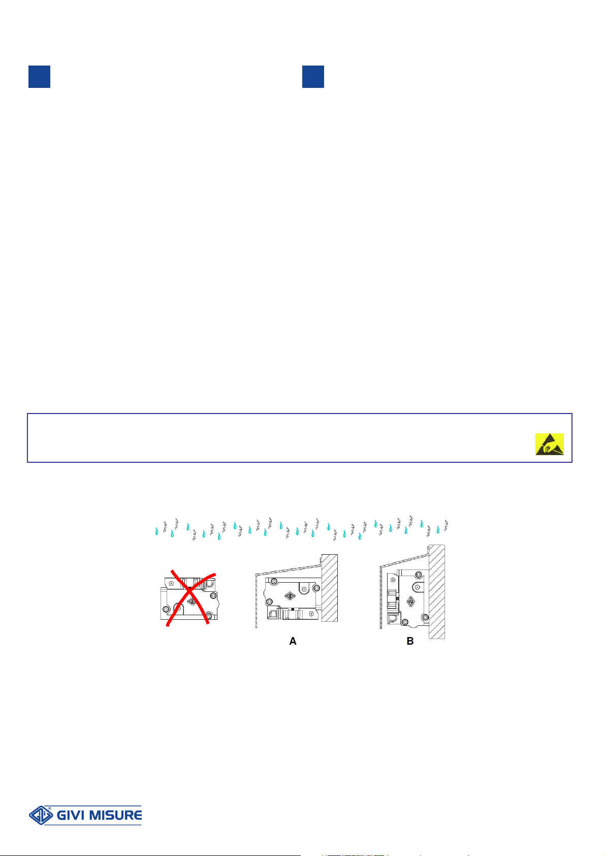
How to prevent condensate, when pressurization is not active: -
Clean frequently the machine guides close to the scale,
avoiding the use of compressed air.
-Protect the scale against coolants as much as possible, avoiding
the stagnation of liquids in the machine’s collecting tank.
-Protect, if possible, the scale from the direct contact with vapours
developed during the working cycle (with upper covers closed
on the side or lower screens to prevent the vapour from laying
on the sealing lips).
:
- .
.
- .
, .
- .
.
- , .
.
- .
.
- .
30 ,
. , ,
,
.
- ,
,
.
.
Possible causes of an ineffective pressurization and remedies: -
Inadequate filtering and air quality. Respect the instructions
provided.
-Insufficient air pressure. Respect the pressure values
suggested by the Manufacturer.
-Filters blocked by liquids or dust. Use self-draining filters or
regularly empty the glasses and replace the filter cartridges.
-Broken, obstructed or blocked air pipes. Verify their integrity.
-Damaged sealing lips. Replace them and verify the respect of
the scale’s alignment tolerances.
-Deactivation of pressurization during machining. Wait at least
30 minutes from the last machining, before disconnecting
pressurization. Make sure that, without pressurization, the scale
is not immersed in stagnating liquids.
-Presence of liquid jets that hit the scale directly or indirectly,
with a higher pressure if compared to the pressurization one.
Use covers to adequately protect the scale from such jets.
5
5
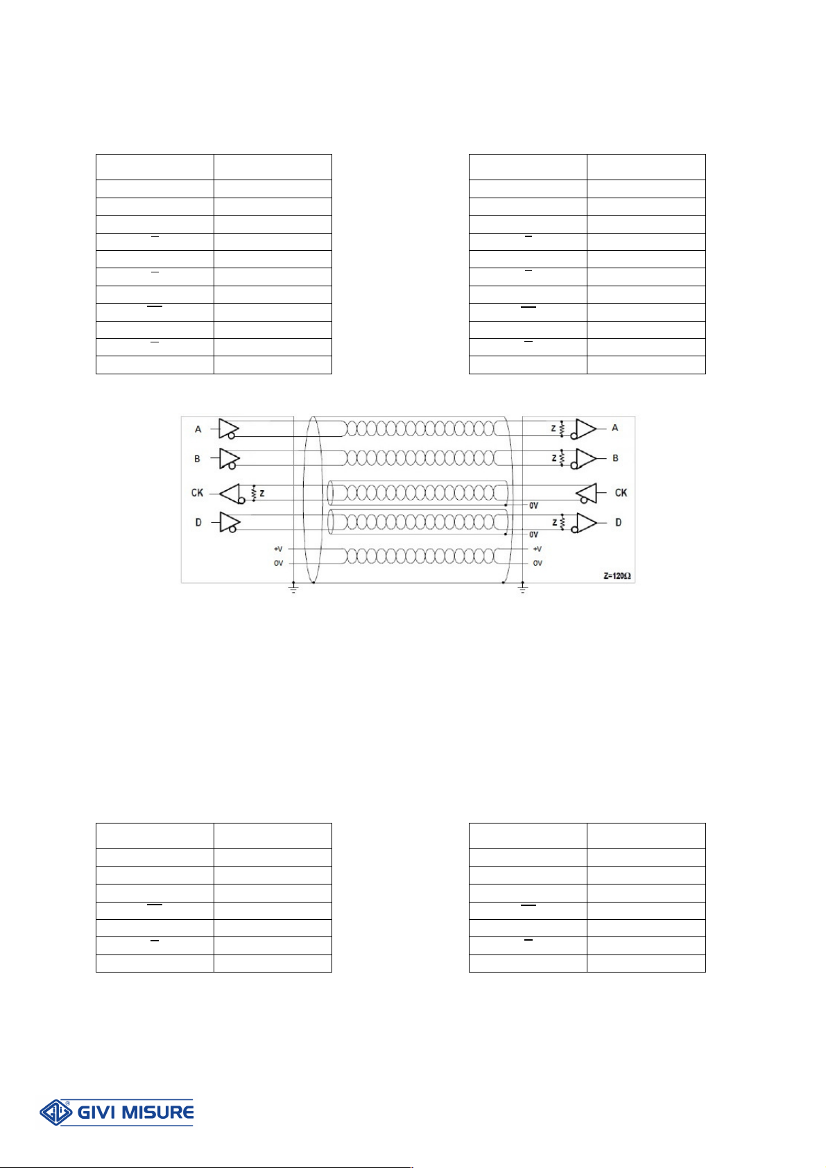
ELECTRICAL CONNECTIONS
+ Digital Output + Serial Output
GVS 206 S 10-
, Æ= 7,1 ,
.
.
(SSI - BiSS).
:
- : 0,35
2
- :0,10
2
GVS 206 S absolute scale is supplied with a 10-wire shielded
cable,
∅
= 7.1 mm, PUR external sheath, with low friction
coefficient, oil-resistant and suitable for continuous movements.
Inside the cable, a further shield for the twisted pair of the digital
signals (SSI - BiSS) is present.
Conductors section:
- supply: 0.35 mm
2
- signals: 0.10 mm
2
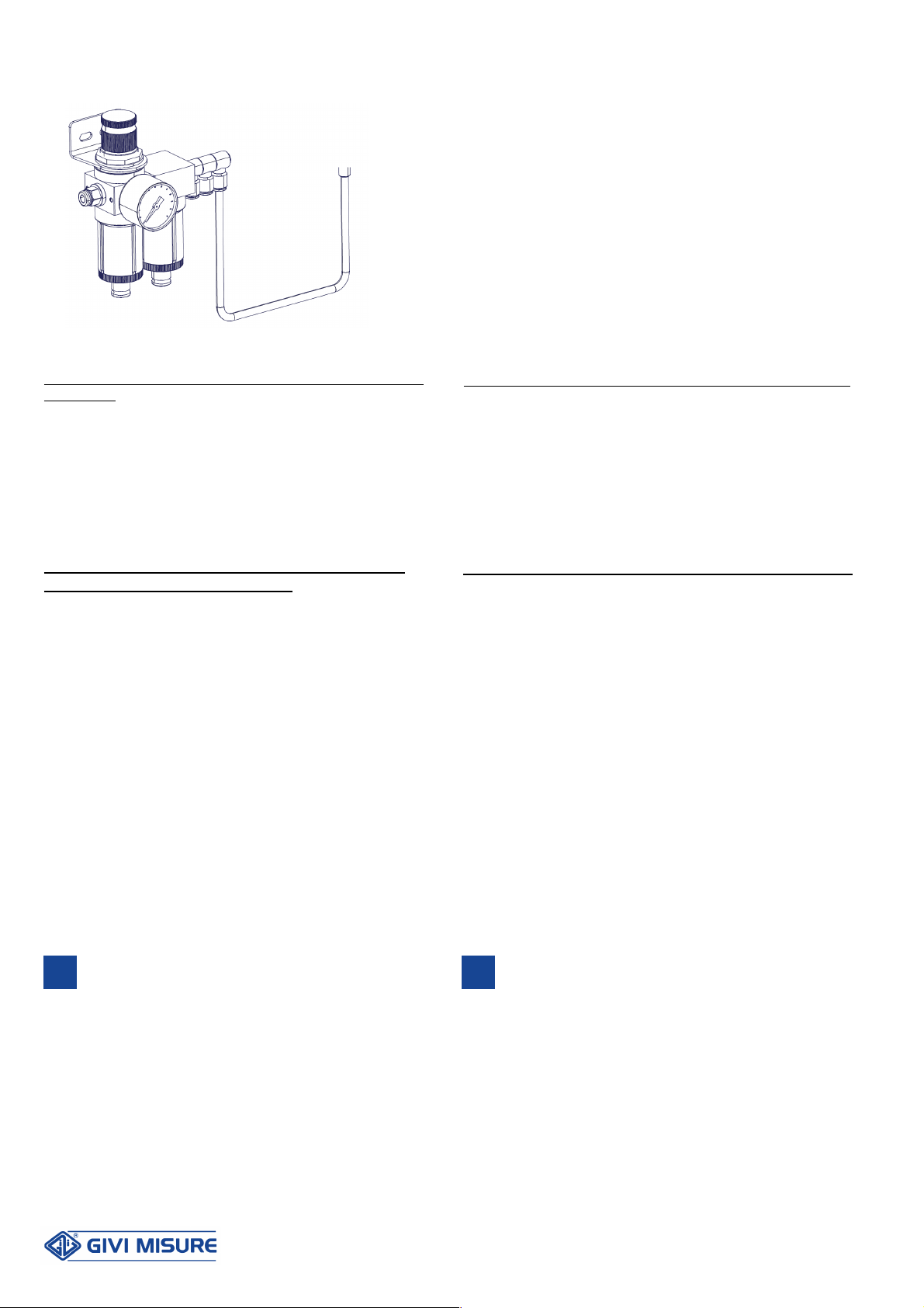
GIVI MISURE ,
.
GIVI MISURE can supply compressed air units that respect the required air quality
classes, allowing the connection of up to three optical scales.