Gizmo GZ2 User manual

GZ2 2018
Instruction Manual

1
Bag A
Parts
Part
Number
Part Name
Quantity
7000
Center Weight
1
1104
Lower Wishbone
4
3030
Rollbar Mount
4
3041
Shock Mount
4
5040
Wishbone Insert
8
5050
C-Clip for Wishbone
8
P06
Downstop Collar
4
3280
Ball Joint Balls
8
3281
Balls for Rollbar Mounts
4
3061
Aluminum Bulkhead
4
1055
Aluminum Rail Mount
4
P04
Arm Hasp
4
1052
Carbon Side Rail
2
1012C or A
Carbon Chassis
1
Screws and Shims
Part
Number
Part Name
Quantity
B2.5x6
Hex Screw B2.5x6
8
B2.5x8
Hex Screw B2.5x8
12
B3x6
Hex Screw B3x6
8
C3x5
Hex Screw B3x5
4
C3x6
Hex Screw C3x6
16
M3x8
Screw 3x8
4
SH05
Shim 0.5mm
4
P3x3
Set Screw P3x3
4
P3x4
Set Screw P3x4
4
P3x6
Set Screw P3x6
4
P3x8
Set Screw P3x8
4

2
A.1 Installation of P06 into the Chassis
A.1.1
Install the qty4 P06 into the chassis individually. Light filing of the edges of the designated holes in the
chassis may be required for easier installation; where the small semi-circle intersects the larger.
Place the P06 with the larger end on a flat surface. Then take the chassis in hand so that the P06 will be
installed from the top of the chassis through to the bottom. The large end of P06 will shoulder on the
upper side of the chassis. Align the designated hole of the chassis with the P06, and push the chassis
onto the P06 piece.
The P06 will snap into place. Repeat for the remaining P06. CA glue can be used to further secure the
piece into the chassis if desired.

3
A.1.2
Install a P3x4 set screw into each of the four P06.
A.1.3
With a hobby-knife, trim off any of the P06 surpassing the bottom side of the chassis.
A.2 Install Arm Joints
Install qty8 3280 Ball Joint Balls using qty 8 C3x6 screws in the indicated diagram below. For a starting
setup, install a 1mm shim below each 3280 for a starting lower roll-center setting.

4
Snap qty 8 5040 Wishbone Inserts onto the already installed 3280’s on the chassis.
A.3 Arms
A.3.1 Wishbone Construction
Instal the 3041 Shock Mount onto the arm using a M3x8 screws to mount it from the bottom.

5
NOTE: Install one M3x3 set screw in the hole of the shock mount that is not being used. This will fix the
shock mount in position and prevent it from rotating.
Install the 3x8 set screw into the shock mount.
Install the P04 and the 3030 Roll Bar Mount to the 1100 Lower Wishbone with qty2 B2.5x6, respectively.
Install the P3x6 into the 3030, and then install the 3281 Ball onto the P3x6.

6
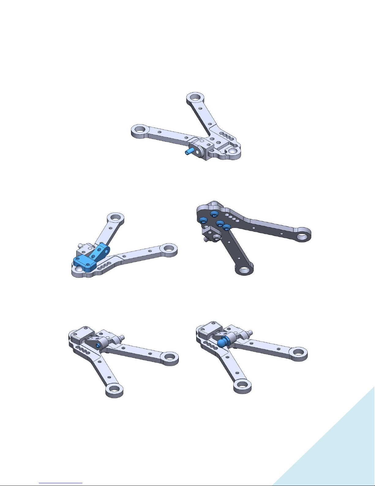
A.3.2 Arm Configuration
Repeat step A.3.1 for each of the four arms.
In the front, mount the square side of the shock mount to the outside on the arm. Use the most inward
position on the arm and the outward mounting hole on the mount for the set screw to mount the shock.
In the rear, use the round part of the shock mount to the outside. Use the second widest position on
the arm holes and the outer hole for the set screw for the shock.
NOTE: Finally, install one M3x3 set screw in the hole of the shock mount that is not being used. This will
fix the shock mount in position and prevent it from rotating.
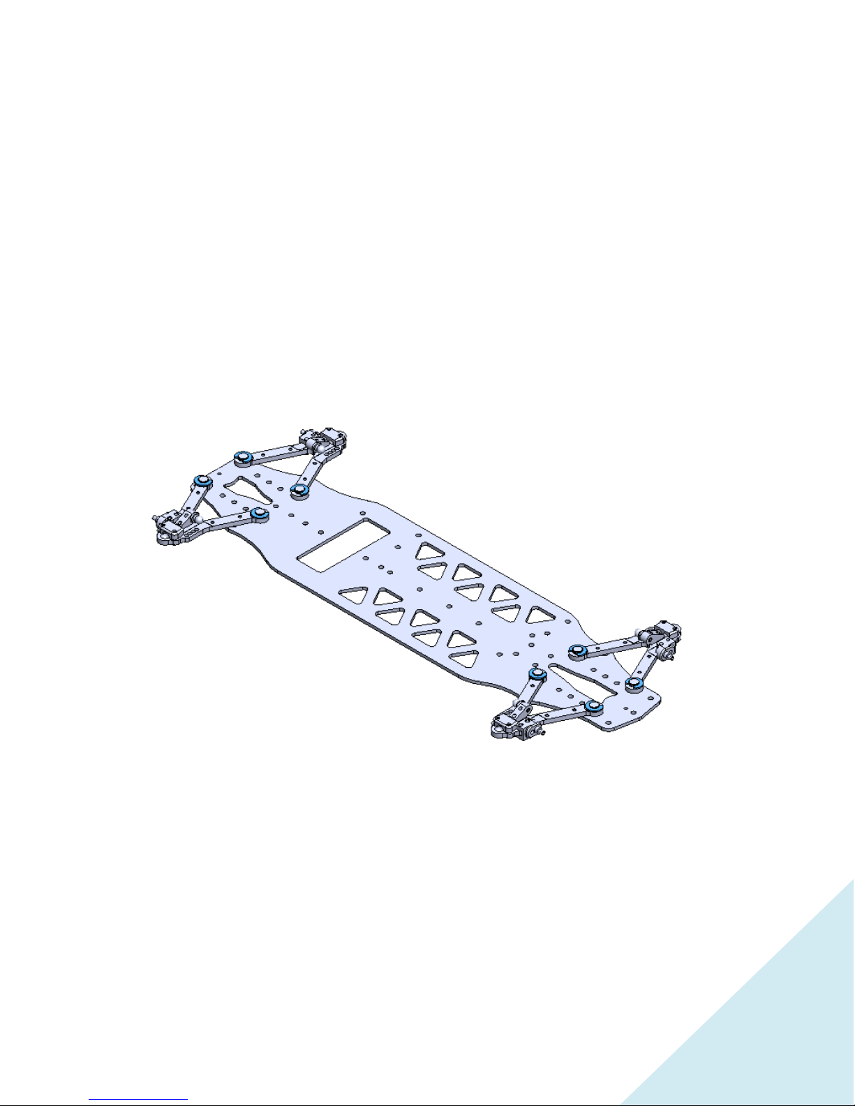
A.3.3 Arm Installation
Then, install each of the four lower arms and secure them with qty2 5050 C-Clip For Wishbones per each
lower arm, as seen above.

7
A.4 Bulkheads
Install the 4 bulkheads to the chassis by using qty2 C3x6 for each.

8
The 7000 Center Weight has four possible mounting screws. The flex of the lower chassis varies
depending on which screws are installed. Install with qty2 C3x6 screws.

9
Bag B
Part
Number
Part Name
Quantity
ST01
Front Axles
2
PIN01
Pin 1.5x7.8mm
6
ST13
Front Universal
Bones
2
ST16
U-Joint Cross
6
UB2
Bushings Kit with
ST11
1
ST17
Universal Ring
2
ST02
Rear Axle
2
ST14
Rear Universal Bones
2
B.1.2 Front Dual Joint Driveshaft
Construct the front axles and the driveshaft bone halves first, to
then join them with ST17.
Use a flat-head with a width of 2.6 mm in the slot of the ST17 to
pry it open and gain clearance to install the two halves of the
driveshaft.
ST01
PIN01
ST16
ST17
PIN01
ST16
ST13
UB2

10
B.1.2 Rear Driveshaft
ST02
ST16
PIN01
ST14
UB2
Twist the flathead here in the ST02 to gain the
clearance to assemble the driveshaft.

11
Bag C
Parts
Part Number
Part Name
Quantity
6020
6x10x3 Bearing
8
3190
Upright Hubs
4
3180
Wheel Axle
4
GZ11701
Arm for Upright Front
2
GZ11702
Rear Toe in Arm
2
ST03
Upright Ball
8
P16
Lock Ring
4
GZ11701
Pivot Ball
4
Screws and Shims
Part Number
Part Name
Quantity
B3x6
Hex Screw B3x6
8
B3x8
Hex Screw B3x8
2
SH10
Shim M3x1.0mm
8
C.1.1 Front Uprights
GZ11701
3190
6020
6020
3180
GZ11703
B3x6
B3x6
B3x8 (steering stop in middle of arm)
ST03
ST03

12
Assemble the first front upright as depicted by the diagram.
Notes:
-Upper outer roll center can be adjusted with different shim sizes below the ST03.
Recommended starting setup is 1mm.
-Roll Center and track-width can also be varied using various shim sizes between the 3190 and
ST03. Recommended starting setup is 1.0 mm.
-Bump steer can also be adjusted by varying the shim size on the steering connection of the arm.
Replicate the other front upright sub-assembly for the opposite side. Thus, flip the GZ11701 and build as
depicted above.

13
C.1.2 Rear Uprights
Assemble the first rear upright as indicated by the diagram.
ST03
B3x6
B3x6
GZ11702
3180
6020
6020
ST03
3190
GZ11703

14
Replicate the other rear upright sub-assembly for the opposite side. Thus, flip the GZ11702 and build as
in the orientation above.
C.1.3 Installation of Uprights and Driveshafts
Install the front and rear drive shafts into the front and rear uprights, respectively. Then install the
uprights into the lower wishbones and tighten down each of P04 to clamp onto the ST03’s. Later, we will
explain the necessary tightness needed on the PO4 for free movement.

15
NOTE: Once the drive shafts are inserted into their respective uprights, install the small plastic retaining
ring onto the driveshaft until it is flat with the hex.

16
Bag D
Parts
Part
Number
Part Name
Quantity
3050
Motor Mount
1
6005
Bearing 5x8x2.5
4
3301
Shaft Pulley
2
5081
18T Pulley
2
9000
Rear Belt
1
9010
Front Belt
1
4050
Pin 2x10mm
2
Screws and Shims
Part
Number
Part Name
Quantity
C3x6
Hex Screw CS
4
SHPS
Shim
5x7x0.1mm
4
B3x6
Hex Screw B3x6
2
5081
5081
9000
9010
3301
3301
6005
6005
6005
6005
B3x6
B3x6
4050
4050
3050

17
The SHPS Shims can be used to shim your spur gears depending on their thickness.
Install the Motor Mount subassembly using qty4 C3x6 screws as indicated above.
C3x6

18
Bag E
Part
Part
Number
Part Name
Quantity
GZ11705
Outdrives V2
4
5071
Spool
1
5010
Diff Left
1
5020
Diff Right
1
4050
Pin 2x10mm
4
4055
Pin 2x8mm
2
8010
O-Ring 24x1mm
1
304990
Diff Gasket
1
304930
Diff Gear Set
1
964031
Diff Washer
3.5x10x0.2mm
4
964050
Diff Washer 5x15x0.3mm
2
6010
Bearing 8x12x3.5
4
3210
Diff Eccentric
4
304980
Diff Cross
1
8020
O-Ring 5x2mm
2
Screws and Shims
Part
Number
Part Name
Quantity
C2.5x8
Hex Screw C2.5x8
4

19
E.1 Spool
Light sanding of the spool on the two outer diameters where the 6010 bearings sit will aid in smooth
assembly.
Must install the 6010 bearings before the GZ11705 Outdrives.
E.2 Rear Differential
Light sanding on the outer diameters where the 6010 bearings sit of the left and right differential
housings will aid in smooth assembly.
Must install the 6010 bearings before the GZ11705 Outdrives. You also need to install 8020 and 964050,
before you install 4050.
5071
GZ11705
6010
3210
4055
4055
6010
GZ11705
3210
Table of contents
Other Gizmo Motorized Toy Car manuals
Popular Motorized Toy Car manuals by other brands

Famosa
Famosa Disney MICKEY MOUSE CLUBH USE manual

Maverick
Maverick Strada TC installation manual

Construct A Truck USA
Construct A Truck USA the Dingo Assembly instructions

Eaelec
Eaelec Z-Scale GMC CCKW 2 1/2 ton Cargo Trucks Assembly instructions

Carrera RC
Carrera RC Track2Wheel Assembly and operating instructions

Carson
Carson IS-200 manual