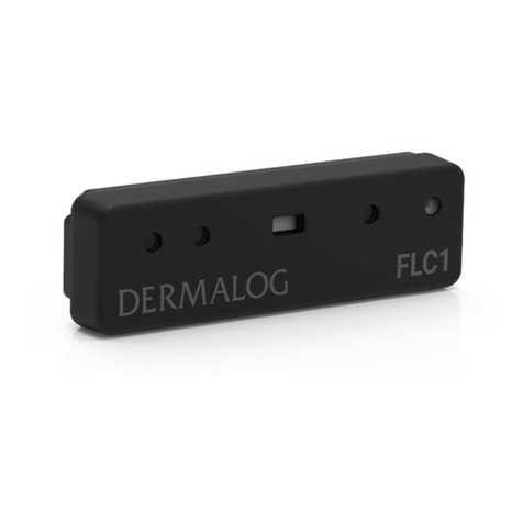
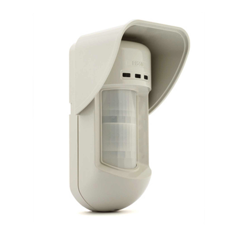
Smarteh LPC-2.SM5 User manual

USER MANUAL
Longo programmable controller
LPC-2.SM5
Multisensor
Version 4
SMARTEH d.o.o. / Poljubinj 114 / 5220 Tolmin / Slovenia / Tel.: +3 6(0) 3 44 00 / e-mail: i[email protected] / www.smarteh.si

Longo programmable controller LPC-2.SM5
Written by SMARTE d.o.o.
Copyright © 2017, SMARTE d.o.o.
User Manual
Document Version: 4
January, 2017
i

Longo programmable controller LPC-2.SM5
STANDARDS AND PROVISIONS: Standards, recommendations,
regulations and provisions of the country in which the devices will
operate, must be considered while planning and setting up electrical
devices. Work on 100 .. 240 V AC network is allowed for authorized
personnel only.
DANGER WARNINGS: Devices or modules must be protected from
moisture, dirt and damage during transport, storing and operation.
WARRANTY CONDITIONS: For all modules LONGO LPC-2 – if no
modifications are performed upon and are correctly connected by
authorized personnel – in consideration of maximum allowed
connecting power, warranty of 24 months is valid from the date of
sale to the end buyer, but not more than 36 months after delivery
from Smarteh. In case of claims within warranty time, which are based
on material malfunctions the producer offers free replacement. The
method of return of malfunctioned module, together with description,
can be arranged with our authorized representative. Warranty does
not include damage due to transport or because of unconsidered
corresponding regulations of the country, where the module is
installed.
This device must be connected properly by the provided connection
scheme in this manual. Misconnections may result in device damage,
fire or personal injury.
azardous voltage in the device can cause electric shock and may
result in personal injury or death.
NEVER SERVICE T IS PRODUCT YOURSELF!
This device must not be installed in the systems critical for life (e.g.
medical devices, aircrafts, etc.).
If the device is used in a manner not specified by the manufacturer,
the degree of protection provided by the equipment may be impaired.
Waste electrical and electronic equipment (WEEE) must be collected
separately!
LONGO LPC-2 complies to the following standards:
•EMC: EN 61000-6-3:2007 + A1:2011, EN 61000-6-1:2007, EN 61000-3-
2:2006 + A1:2009 + A2: 2009, EN 61000-3-3:2013
•LVD: IEC 61010-1:2010 (3rd Ed.), IEC 61010-2-201:2013 (1st Ed.)
Smarteh d.o.o. operates a policy of continuous development.
Therefore we reserve the right to make changes and improvements to
any of the products described in this manual without any prior notice.
MANUFACTURER:
SMARTE d.o.o.
Poljubinj 114
5220 Tolmin
Slovenia
ii

Longo programmable controller LPC-2.SM5
Longo programmable controller LPC-2.SM5
1 ABBREVIATIONS................................................................................1
2 DESCRIPTION...................................................................................2
3 FEATURES.......................................................................................3
4 OPERATION.....................................................................................4
4.1 Operational modes.....................................................................4
4.2 Parameters..............................................................................4
4.3 IR learn, receive and transmit.......................................................6
5 INSTALLATION..................................................................................7
5.1 Connection scheme....................................................................7
5.2 Mounting instructions.................................................................9
5.3 Module labeling.......................................................................11
6 TEC NICAL SPECIFICATIONS................................................................12
7 SPARE PARTS..................................................................................13
8 C ANGES......................................................................................14
9 NOTES..........................................................................................15
iii

Longo programmable controller LPC-2.SM5
ABBREVIATIONS
Sorted by order of appearance in document:
LED Light emitting diode
SEL Selector
CO2 Carbon dioxide
PIR Passive infrared sensor
IR Infrared
1

Longo programmable controller LPC-2.SM5
2 DESCRIPTION
The LPC-2.SM5 is a multi sensor which consists of the following sensors: CO2 sensor for CO2 level
measurements, lux sensor for light intensity measurements, PIR sensor for occupancy sensing and IR
receive/transmit for IR communication.
Measuring CO2 level and light intensity provides the information needed for achieving good work
conditions. Information about occupancy of the room can be used for energy saving algorithms. IR
transmit feature can be used for remote controller substitution, for example air conditioning can be
controlled from Smarteh main module via LPC-2.SM5 in parallel with remote controller. On the other
hand, IR receive feature can be used for receiving commands to the main module from Smarteh
remote controller, smartphone or other remote controller. LPC-2.SM5 can recognize RC-5 IR protocol
which is used in Smarteh remote controller or 15 different learned IR commands which can be
learned in IR learning mode. Only learned commands can be transmitted.
LPC-2.SM5 is controlled and powered from the main module (e.g., LPC-2.MC8, LPC-2.MC9) via
Smarteh bus.
2

Longo programmable controller LPC-2.SM5
3 FEATURES
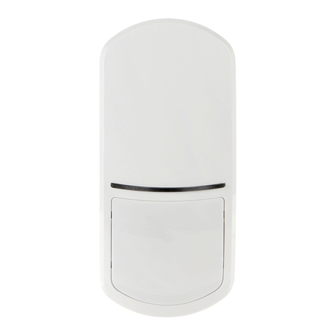
Figure 1: LPC-2.SM5 multisensor
Table : Features
CO2 sensor for CO2 measurement
PIR sensor for occupancy detection
Lux sensor for light intensity measurement
IR receive/transmit
Mounting with integrated magnets or screws1
2 diagnose LED
1 Screws are not supplied with sensor.
3

Longo programmable controller LPC-2.SM5
4 OPERATION
LPC-2.SM5 can be in one of two operational modes - normal or error. When LPC-2.SM5 is in normal
mode, module parameters can be read or written via Smarteh IDE software.
4. Operational modes
Normal
Communication with the main module is working. Only green “PWR” LED2 is turned on.
Error
In case of communication fault, red “ERR” LED1 will turn on.
4.2 Parameters
If parameter is set to logical “1”, is considered to be active, enabled or set. If parameter has logical
value “0” is considered to be inactive, disabled or cleared.
Parameter can be a command or feedback. When parameter is marked as feedback it means that
LPC-2.SM5 is sending information to the main module. On the other hand, command represents
request from the main module to the LPC-2.SM5.
Command:
IR command number selection for transmit [oIrCmdSendNum]: This parameter is used to
select the IR learned command which will be used for transmit.
Type: WORD
Raw to engineering data: 1 .. 15 IR transmit command 1 .. IR transmit command 15→
IR command transmit control bit [oIrCmdSend]: When this bit goes to "1", selected IR
command in oIrCmdSendNum is transmitted.
Type: BOOL
Raw to engineering data: “0” No transmit→
“1” Transmit selected IR command →
IR protocol selector [oIrProtocolSel]: Selector for IR receive protocol.
Type: WORD
Raw to engineering data: 0 Learned IR commands→
1 RC-5 IR protocol→
Feedback:
Actual CO2 value [iCo2]: Actual measured CO2 value limited to 200 .. 2000 range. If CO2
value of the CO2 sensor goes above 2000, than iCo2 is 2000. If it goes below 200, than iCo2
is 200.
Type: WORD
Raw to engineering data: 200 .. 2000 200 .. 2000 ppm→
9999 CO2 sensor not readable→
CO2 sensor run status bit [iCo2Status]: This bit is "1" whenever CO2 value of the CO2
sensor goes below 200 ppm or above 2000 ppm.
Type: BOOL
Raw to engineering data: “0” OK→
“1” CO2 value of the CO2 sensor→ out of iCo2 range
4

Longo programmable controller LPC-2.SM5
Actual light intensity value [iLight]: Actual measured light intensity value.
Type: WORD
Raw to engineering data: 0 .. 1490 0 .. 1490 lux→
PIR sensor detection status [iPirDetect]: Moving person or object presence indication.
Type: BOOL
Raw to engineering data: “0” →No moving person or object presence indication
“1” →Moving person or object presence indication
Toggle communication bit [iComm]: At each valid Rx packet from main module, this bit is
toggled.
Type: BOOL
IR command number received value [iIrCmdRecNum]: This parameter depends on the
oIrProtocolSel parameter. Latency between touched button on the remote controller and
reception on the main module is max. 1 s.
Type: WORD
If oIrProtocolSel
is "0":
When LPC-2.SM5 receives an IR command, value of iIrCmdRecNum corresponds to the
number of the IR learned command. Value is set back to 0 after next communication
cycle with main module or after approximately two seconds regardless
communication.
Raw to engineering data: 1 .. 15 IR receive learned command 1 .. IR receive →
learned command 15
is "1":
When LPC-2.SM5 receives an IR command, value of iIrCmdRecNum corresponds to the
number described below in binary code which includes toogle bit, address code and
data code of the RC-5 protocol. When button is released, value gets to 0 after next
communication cycle with main module or after approximately two seconds
regardless communication.
Raw to engineering data:
5

Longo programmable controller LPC-2.SM5
4.3 IR learn, receive and transmit
LPC-2.SM5 module can be learned to recognize 15 different IR commands. Module enters IR learning
mode as soon as the left pair of DIP switches (S1) are not in position for "No learning - receive only" –
see table 4.
IR learn is demonstrated on the example on how to learn LPC-2.SM5 the IR command "power ON"
from third-party IR remote controller for air conditioning and store it under command 15 in the LPC-
2.SM5 internal memory. IR receive and transmit is demonstrated on the example how to verify
stored IR commands.
IR learn
Set the S1 DIP switches to the setting than corresponds to the number under which IR command will
be stored. In this example, switches must be set to setting "learning mode for command 15". Once
this is done, LPC-2.SM5 is ready to receive the IR command from the remote controller and store it
to internal memory under command 15.
Press the button on the IR remote controller which you want it to be stored under command that is
set with DIP switches on LPC-2.SM5. In this example, press "power ON" button on the IR remote
controller. Once the button has been pressed, the LPC-2.SM5 stores the IR command to internal
memory, in this example under command 15. LPC-2.SM5 will not store any other command under
command 15, unless S1 DIP switches has been changed to other setting and back to the setting
"learning mode for command 15".
IR receive
Which protocol should be used for IR receive, user can select with IrProtocolSel parameter. To check
if the IR command has been learned and stored correctly IrProtocolSel parameter must be "0".
Set the DIP switches to the setting "No learning - receive only" and than press button "power ON" on
the IR remote controller. If the received IR command corresponds to any of the IR commands stored
in the LPC-2.SM5 internal memory, the command number under which the received IR command has
been stored will be shown in the feedback parameter iIrCmdRecNum. In this example, number 15
should be shown.
If IrProtocolSel is set to "0" and DIP switches to the setting "No learning - receive only" than LPC-
2.SM5 will receive learned IR commands only.
If IrProtocolSel is set to "1" and DIP switches to the setting "No learning - receive only" than LPC-
2.SM5 will receive RC-5 IR protocol only.
Be advised that during IR transmit, IR receive is blocked.
IR transmit
In order to check if the IR command that was stored can also be transmitted correctly, the LPC-
2.SM5 should be used as a substitution of the IR remote controller. On the main module, number 15
should be written to the LPC-2.SM5 command oIrCmdSendNum. This command selects IR command
which is stored under number 15 for transmit. IR transmit is executed once oIrCmdSend is set to
logical “1”. In this example, air conditioning should be turned ON.
Procedure for IR learn can be repeated for 15 different IR commands. DIP switch setting corresponds
to learning mode for one of 15 commands and IR receive only mode – see table 4.
The IR commands may also be learned during manufacturing process - consult with Smarteh.
6

Longo programmable controller LPC-2.SM5
5 INSTALLATION
5. Connection scheme
Figure 2: Connection scheme
7

Longo programmable controller LPC-2.SM5
Table 2: K
K1.1 GND Ground
K1.2 7 .. 30 V DC Power supply input
K1.3 Standard RS-485 A Data receive/send line A
K1.4 Standard RS-485 B Data receive/send line B
Table 3: LEDs
LED1: red Communication ON: RS-485 communication fault
OFF: RS-485 communication OK
LED2: green Power supply ON: power supply OK
OFF: power supply missing or power off
Table 4: S
SEL for IR Switch Switch 2 Switch 3 Switch 4
No learning - IR
receive only OFF OFF OFF OFF
Learning mode for
command 1 OFF OFF OFF ON
.. .. .. .. ..
.. .. .. .. ..
Learning mode for
command 14 ON ON ON OFF
Learning mode for
command 15 ON ON ON ON
Table 5: S2
RS-485
ADDRESS Switch Switch 2
0 OFF OFF
1 OFF ON
2 ON OFF
3 ON ON
8

Longo programmable controller LPC-2.SM5
5.2 Mounting instructions
Figure 3: Housing dimensions
Dimensions in milimeters.
All connections, module attachments and assembling must be done
while module is not connected to the main power supply.
Mounting instructions:
1. Set the correct RS-485 address for LPC-2.SM5 (refer to the table 5).
2. Install the LPC-2.SM5 module on the position which provides maximum effect for its features
with the magnets or screws2. Magnets can be pushed to the other side of abutment surface if
needed.
3. Connect interconnection cable to the main module.
LPC-2.SM5 module must be installed properly, isolating any potential connection with electrical
sources other than power supply from main module. Improperly installed module may cause failure
of the module itself, other devices on the same wiring, main module or may lead to fire or personal
injury.
LPC-2.SM5 is connected to the main module with interconnection cable (e.g. SSK, ICM-7). When
more modules are connected to the main module, splitter (e.g. SPL-2) is also required (figure 2).
NOTE: Signal wires must be installed separately from power and high voltage wires in accordance
with general industry electrical installation standard.
2 Screws are not supplied with sensor.
9

Longo programmable controller LPC-2.SM5
Figure 4: LPC-2.SM5 orientation
Figure 5: PIR sensor detection area
10

Longo programmable controller LPC-2.SM5
5.3 Module labeling
Figure 6: Labels
Label 1 (sample): Label 2 (sample):
Label 1 descriptions:
1. LPC-2.SM5 is the full product name.
2. P/N: 225SM516001001 is the part number.
•225 – general code for product family,
•SM5 – short product name,
•600 – sequence code,
•16 – year of code opening,
•001 – derivation code,
•00 – version code (reserved for future W and/or SW firmware upgrades).
3. D/C: 0 / 6 is the date code.
•0 – week and
•6 – year of production.
Label 2 descriptions:
1. S/N: SM5-S9- 600000003 is the serial number.
•SM5 – short product name,
•S9 – user code (test procedure, e.g. Smarteh person xxx),
•600000003 – year and current stack code,
•16 – year,
•00000003 – current stack number; previous module would have the stack number
00000002 and the next one 00000004.
11
S/N: SM5-S9-1600000003
LPC-2.SM5
P/N:225SM516001001
D/C: 01/16

Longo programmable controller LPC-2.SM5
6 TECHNICAL SPECIFICATIONS
Table 6: Technical specifications
Power supply from main module
Interconnection connector type RJ-12 6/6
Power consumption 0.5 W
CO2 measurement range 200 .. 2000 ppm
Light intensity measurement range 0 .. 1490 lux3
PIR sensor detection range max. 12 m
PIR sensor detection area
vertical: 92° (± 46°)
horizontal: 102° (± 51°)
detection zones: 92
PIR sensor conditions concerning
detection
the temperature difference between the moving
person or object and the surroundings should be
superior to 4 °C (7.2 °F).
movement speed: 1.0 m/s
target concept is human body (size: 700 x 250 mm)
IR frequency carrier 38 k z
IR max. pulse length in protocol used for
learning 16 ms
IR min. pulse length in protocol used for
learning 250 us
IR max. number of pulses for learning
single IR command 540
Dimensions (W x x D) 109 x 40 x 20 mm
Weight 65 g
Maximum altitude 2000 m
Mounting position any
Ambient temperature 0 to 50 °C
Ambient humidity max. 95 %, no condensation
Transport and storage temperature -20 to 60 °C
Protection class IP 20
3 Due to various spectral sensitivity of the various lux sensors on the market, the actual light intensity may vary.
12

Longo programmable controller LPC-2.SM5
7 SPARE PARTS
For ordering spare parts following Part Numbers should be used:
LPC-2.SM5 Multisensor
LPC-2.SM5 P/N: 225SM516001001
Interconnection cable
ICM-x P/N: 203ICMxxxxxxxx
Splitter
SPL-2 (1/8) P/N: 206SPL04002001
13

Longo programmable controller LPC-2.SM5
8 CHANGES
The following table describes all the changes to the document.
Date V. Description
15.01.17 4 Technical update.
16.11.16 3 Added IR data.
28.10.16 2 Parameter added in section 4.2.
30.09.16 1 The initial version, issued as LPC-2.SM5 User Manual.
14

Longo programmable controller LPC-2.SM5
9 NOTES
15
Table of contents
Other Smarteh Security Sensor manuals
