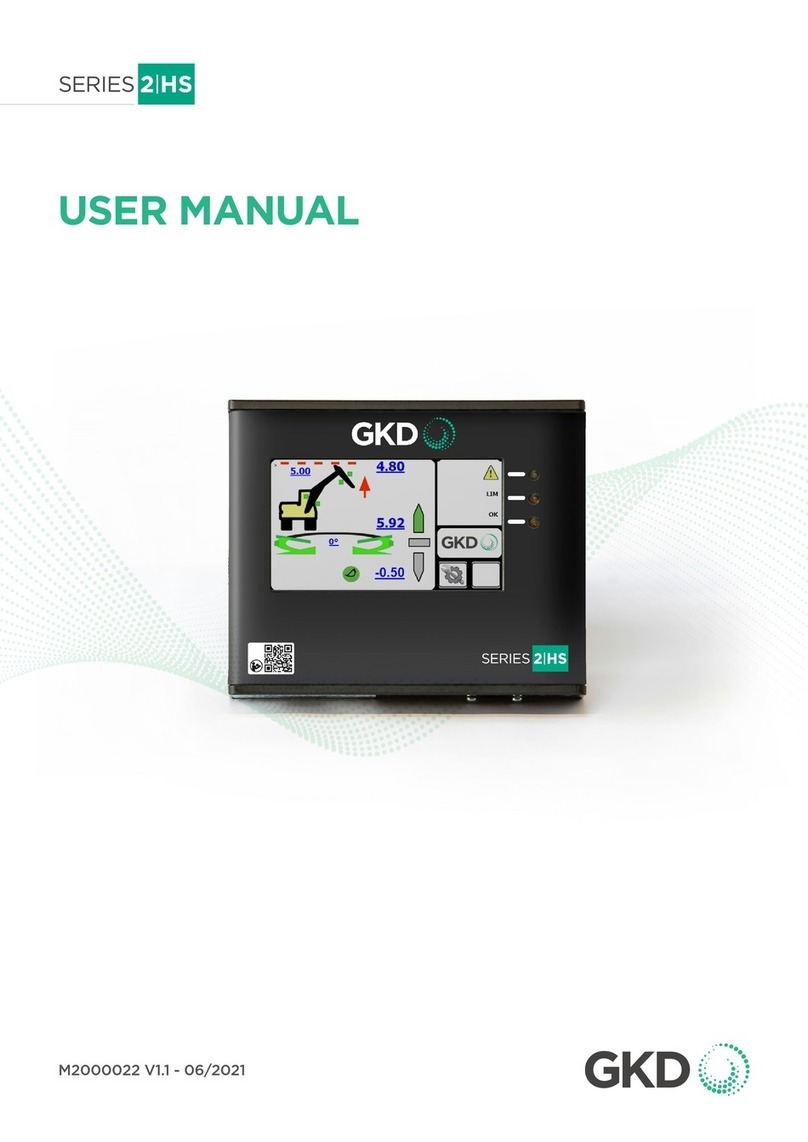
GKD 1H Series User manual

HEIGHT LIMITER
M1000005 V1.5 - 11/2021
COPYRIGHT NOTICE
Intended audience: This document contains sensitive
information. It may not be shared with other parties without
the express written permission of GKD Technologies Ltd.
INSTALLATION MANUAL

M1000005 V1.5 - 11/2021
www.gkdtechnologies.com 2
CONTENTS
Page
1 OVERVIEW 4
2 MAIN SYSTEM COMPONENTS 4
2.1 Display 4
2.2 Angle Sensor 4
3 SERIES 1-H INDICATORS AND CONTROLS 5
4 SYSTEM LAYOUT 6
5 DISPLAY INSTALLATION 7
5.1 Electrical Connections 7
5.2 Relay Outputs 7
5.3 CAN Bus Connection 7
6 ANGLE SENSOR INSTALLATION 8
6.1 GRAVITY V angle sensor option 8
6.2 Terminating Resistor 9
7 MOTION CUT SOLENOID VALVE INSTALLATION 10
7.1 Operating Principle – motion cut valve 10

www.gkdtechnologies.com M1000005 V1.5 - 11/2021
3
8 CALIBRATION 11
8.1 Horizontal Position Setting 11
9 SETTING A HEIGHT LIMIT 12
10 FAULT FINDING 13
10.1 Fault LED 13
10.2 Angle sensor, no LED 13
10.3 Angle sensor, red LED 13
10.4 No motion cut or external alarm 13
10.5 Motion cut not working 13

M1000005 V1.5 - 11/2021
www.gkdtechnologies.com 4
1 OVERVIEW
The Series 1-H is a height limiting system intended for use on excavators, loaders, teletrucks
or similar type machines.
The system monitors the angle of the primary boom or arm and compares this angle against
a previously stored limit, set by the machine operator. When the boom is lifted to the point
where the boom angle approaches the stored “limit” angle, an internal relay is switched
within the display and the state of the relay output from the display switches. If this output
is connected to an external sounder, the sounder will alarm at the height limit. If this output
is connected to a solenoid valve controlling the boom lift function the boom lift function
will be cut, preventing movement beyond the height limit. The boom lower function is still
active, allowing boom movement back to a safe position.
Because the Series 1-H system references the boom position against gravity rather than
against the machine base, machine base gradient is automatically compensated for in
operation.
2 MAIN SYSTEM COMPONENTS
2.1 Display
The display is mounted in the machine cab at the operator station, in a position easily
accessible by the machine operator. The display has a flying lead, which supplies power to
the system and includes the
relay outputs used to activate an external sounder and / or a motion cut valve. The display
also has a 12mm CAN bus connection, which is connected to the angle sensor mounted on
the machine boom.
2.2 Angle Sensor
The angle sensor used in this system is a gravity referenced angle sensor, called a GRAVITY V.
In all installations, the angle sensor should be mounted on the first Boom of the machine.
For more information, please see page 8.

www.gkdtechnologies.com M1000005 V1.5 - 11/2021
5
3 SERIES 1-H INDICATORS AND CONTROLS
Fault
On
Set Limits
Set/Test
O On
Indicator LEDs in ACTIVE mode:
(see detailed notes in sections below)
Indicates fault with the Series 1-H system
or configuration
Indicates System has reached 95% of
maximum height limit.
Indicates System has reached 75% of
maximum height limit.
Indicates System is below 75% of the
maximum height limit
Indicates System Power is ON
Set/Test Button:
= SET when Key Switch at Set Limit
= TEST when Key Switch at On
Key Switch:
O = System in Inactive Mode
On = System in Height Limit Active Mode
Set Limits = System in Setup Mode

M1000005 V1.5 - 11/2021
www.gkdtechnologies.com 6
External
Sounder
(optional)
4 SYSTEM LAYOUT
RED: = +V IN
BLUE = Relay Common
BLACK = 0V (Chassis)
YELLOW = Relay N/O
GREEN = Relay N/C
Connect to
machine ignition
via a 5A Fuse
Gravity V Angle Sensor
Motion Cut
Solenoid

www.gkdtechnologies.com M1000005 V1.5 - 11/2021
7
5 DISPLAY INSTALLATION
The display should be installed in the machine cab at the operator station, in a position
where it can easily be seen and accessed by the operator. Normally this will be on the
operator’s right side, near the front of the cab.
The display is mounted using a RAM bracket, which will enable the display to be positioned
facing the operator. Mount the RAM bracket to a solid surface that is capable of supporting
the weight of the display.
Do not modify the frame of the machine by drilling or welding as this will compromise the
ROPS / FOPS integrity of the structure.
Ensure that machine controls, operator view of indicator lamps and gauges, and window /
door operation are not obstructed.
5.1 Electrical Connections
The display has a flying lead through which all electrical connections are made. A suitable
power supply should be identified, this should be ignition switched and capable of supplying
5A to the system.
The Series 1-H system should be protected by a 5A fuse on the ignition power supply.
Connect both the RED and BLUE wires to the +V power supply, with the fuse protecting both.
Connect the BLACK wire to a good 0V connection, preferably directly to the vehicle chassis.
5.2 Relay Outputs
The Series 1-H outputs are through the GREEN and YELLOW wires. Note that these will
be +V outputs, if either are not used they should be insulated and protected from the
possibility of short circuit against a 0V chassis component or connection.
• The GREEN wire will be live when the height limit is reached, and is therefore suited to
driving a sounder or lamp indicating that the limit has been reached.
• The YELLOW wire will be live when working, and will switch o when the height limit is
reached. It is suited to driving a solenoid valve controlling the boom lift function, and will
motion cut the hydraulic function at height limit.
5.3 CAN Bus Connection
The 12mm connector on the base of the display is the CAN bus connection to the angle
sensor, and should be connected to the angle sensor using the supplied cable.

M1000005 V1.5 - 11/2021
www.gkdtechnologies.com 8
6 ANGLE SENSOR INSTALLATION
6.1 GRAVITY V angle sensor option
The GRAVITY V angle sensor is installed onto the boom to be monitored.
Identify a position for the sensor on the side of the boom, where it is not likely to be
damaged by machine components or to catch moving cables or hydraulic hoses as machine
components articulate.
It is preferable that the sensor should be installed as close to the boom base pin as is
practical, to minimize acceleration and deceleration forces imposed on the sensor as the
boom moves up or down.
The sensor should be orientated so that the long edge is parallel with the boom being
monitored.
Sensor mounted parallel
to line drawn through end
points of monoboom
Sensor mounted parallel to the extending
boom. The sensor can be installed on either
side of the equipment, but this will depend
on what access is available.
Sensor
Sensor

www.gkdtechnologies.com M1000005 V1.5 - 11/2021
9
Once a suitable position has been identified, remove a small area of paint from the install
site at each end of the angle sensor mounting shoe, and weld the mounting shoe to the arm
using the V shaped cutout at each end of the mounting shoe.
Treat the area of the weld with anti rust compound and paint to prevent rust forming.
Install the angle sensor onto the mounting plate using the four nuts provided in the kit, and
connect the angle sensor to the display using the 12mm CAN cable provided.
Ensure that the CAN bus cable between the angle sensor and the display is routed back
into the cab in such a way that it will not be damaged by moving machine components or
external forces such as trees or bushes when working in overgrown areas. Provide sucient
free cable at boom or machine articulation points to allow full movement of the booms or
equipment without straining the cables.
6.2 Terminating Resistor
A terminating resistor is provided, this should be fitted to the free 12mm connector on the
other end of the angle sensor. The terminating resistor is required to be fitted at the end of
any CAN bus line to maintain an ecient CAN bus loop.
Weld Weld
Terminating
Resistor

M1000005 V1.5 - 11/2021
www.gkdtechnologies.com 10
7 MOTION CUT SOLENOID VALVE INSTALLATION
If motion cut on height limit is required, a three port solenoid valve should be installed in the
low pressure Pilot hydraulic line between the machine control lever and the high pressure
valve block.
Identify the pilot line controlling the boom lift hydraulic function.
With the boom fully lowered and the engine o, remove the pilot line hydraulic fitting from
the valve block, and route it through the three port solenoid valve as per the diagram below.
Solenoid Energized (Motion Allowed)
Solenoid NOT Energized (Motion Cut)
7.1 Operating Principle – motion cut valve
When working below the set height limit, boom up motion is allowed and the solenoid valve
will be powered. Hydraulic oil can flow freely between the machine control lever and the
high pressure valve block. The tank dump line from the solenoid valve is blocked in this valve
state.
When the height limit is reached, the power supply from the Series 1-H display to the
solenoid valve is cut and the valve closes. The pilot line from the machine control lever is
now blocked, and the pilot line to the high pressure valve block is connected to the tank
dump port within the solenoid valve to allow any residual pressure in the pilot line to be
dumped to tank, thus preventing further upward motion and causing immediate motion
cut. When the boom is dropped back below the height limit, power to the solenoid valve is
restored and normal operation is resumed automatically.
From Control Lever
Pressure Dump to Tank
To Main Valve Block
From Control Lever
Pressure Dump to Tank
To Main Valve Block

www.gkdtechnologies.com M1000005 V1.5 - 11/2021
11
8 CALIBRATION
Once installation has been completed, set the Series 1-H display key switch to “On” mode
and switch on the ignition, causing the Series 1-H system to power up.
At power up, all 5 LEDs will come on and the internal sounder bleeps as a self-test.
The LEDs will then go o in turn.
When powered up with no Horizontal reference or Height Limit set, the red “Fault” and “!”
LEDs flash alternately to show the system is in an undefined fault state. This is normal on
initial power up.
8.1 Horizontal Position Setting
The Horizontal Position is usually set once, when the Series 1-H system is first installed.
The Horizontal Position should be set again if the Series 1-H control unit or the boom angle
sensor are modified, moved or replaced.
Setting the horizontal position is important because the Series 1-H system does not know
which side of the boom the angle sensor is fitted, and the direction of “Up” is reversed if the
sensor is fitted to the opposite side of the boom. Setting the Horizontal position provides
a “low boom” reference to the Series 1-H, and as long as the height limit is set ABOVE the
Horizontal position, the Series 1-H sensor knows which way is “Up”.
Park the machine on level ground and set the boom as near to Horizontal as practical (or,
set the boom to it’s lowest practical position).
Set the Key switch to the Height Limit Inactive position (a special case for initial Horizontal
setting).
Press and hold the Set / Test button for 10 seconds, initially the Yellow LED flashes. Continue
to hold the Set button On and after 10 seconds the Yellow LED stays permanently On to
indicate that the Series 1-H is ready to accept the Horizontal setting.
While still holding the Set button ON, turn the key switch to Set Limit & then release the
button.
The yellow LED goes O and the Green LED comes On for 3 seconds. After 3 seconds the
red !! LED comes on to demonstrate that the Horizontal setting has been accepted.
The Horizontal Position has now been set. Set the key switch to Active mode. The red !! LED
flashes fast as no Height Limit is set.
(The Horizontal setting can be reset at any time by following the procedure above. Any
Height Limit setting is cleared if the Horizontal setting is changed.)
Once the Horizontal position has been set, set a height limit to activate the system.

M1000005 V1.5 - 11/2021
www.gkdtechnologies.com 12
9 SETTING A HEIGHT LIMIT
To set a height limit, turn the key switch to the “SET” position and raise the boom of the
machine to the desired maximum height position.
Note: the configuration of the machine equipment will depend on how it is positioned when
setting a height limit. See below for how to achieve this.
• Mono-boom or machines with a hydraulic adjustable boom. Set the equipment in the
worst case, i.e. with the dipper and/or fore boom at full reach, then position at the
required height.
• Teletruks or machines with extending booms. Extend the boom to its maximum extended
length, then position at the required height.
Press the “SET / TEST” button. The current boom angle will be stored as the maximum
allowed boom angle.
Turn the key switch back to the “ACTIVE” position and lower the boom.
If desired, the key can be removed from the Series 1-H in the “Active” position to prevent
tampering with the stored height limit.
Normal operation is now possible whilst the boom angle is below the sored height limit.
As the boom is lifted towards the stored height limit, The AMBER LED on the Series 1-H
display will light up as the boom moves through 75% of the available height range, and at
95% of the available height range a RED LED will light up on the display, the display internal
alarm will sound, and the internal relay within the display will switch state.
Where an external sounder or lamp is installed and powered from the GREEN wire from the
Series 1-H, power will be provided to the connected device.
Where a hydraulic solenoid valve has been connected to the YELLOW wire from the Series
1-H display, power is cut o and motion is cut on the boom raise circuit.
For convenience, the installer username and password are printed onto a label on the unit,
which should be removed following installation.

www.gkdtechnologies.com M1000005 V1.5 - 11/2021
13
10 FAULT FINDING
10.1 Fault LED
If the “Fault” LED is lit, a connection error is present between the Series 1-H display and
the angle sensor. Check the CAN bus cable between the display and the angle sensor for
damage or incorrect connection. NOTE: On first switch on, before the Horizontal boom
position has been learned, it is normal for the fault light to flash.
10.2 Angle sensor, no LED
The angle sensor LED should be flashing GREEN whilst the system is powered.
No LED showing on the angle sensor may be caused by angle sensor failure, but is more
likely to indicate that no power is being supplied to the sensor through the CAN bus cable.
10.3 Angle sensor, red LED
Should the angle sensor LED be RED, an angle sensor internal fault has occurred.
10.4 No motion cut or external alarm
Check to make sure that the display internal relay connection (BLUE wire) is connected to
a +V ignition switched source, as the power to the green and yellow output wires is derived
from the blue power input wire.
10.5 Motion cut not working
Ensure that the Horizontal boom position has been learned by the system (see page 14) and
that a valid height limit ABOVE the horizontal position has been set, and that the key switch
is in the ACTIVE position. If still not working, check the YELLOW wire output to the solenoid
valve for power, and that the solenoid has a good chassis earth to the 0V connection.
DISCLAIMER
Incorrect installation of any part and or incomplete calibration will aect the correct
operation of the Series 1-H.

M1000005 V1.5 - 11/2021
www.gkdtechnologies.com 14
INSTALLER NOTES

www.gkdtechnologies.com M1000005 V1.5 - 11/2021
15

©GKD Technologies 11-2021
GKD Technologies reserve the
right to change these instructions in
line with the policy of continuous improvement.
17 Cobham Road, Ferndown Industrial Estate, Wimborne, Dorset, UK. BH21 7PE
+44 (0)1202 861 961 sales@gkdtec.com www.gkdtechnologies.com
DISCLAIMER
Incorrect installation of any part and or incomplete calibration
will aect the correct operation of the Series 1-H.
If in doubt contact GKD Technologies.
Other manuals for 1H Series
1
Table of contents
Other GKD Controllers manuals
Popular Controllers manuals by other brands

thomann
thomann the t.racks DSP 4x4 Amp 4.250 user manual

SE Controls
SE Controls OS2 Technical information and operating instructions

Norac
Norac UC5 Topcon X30 installation manual

weintek
weintek MT-500 Series installation instructions

ATON
ATON AH66T installation manual

Giacomini
Giacomini KLIMAdomotic KPM45 Air quick start guide