SE Controls OS2 Manual

OS2 230v AC Controller
Technical Information and Operating Instructions

1
OS2 230v AC Controller
Installation and User Manual
Table of Contents
Section
Reference
Page
1.0
Introduction
2
2.0
Packaging & preparation
3
3.0
Mounting
3
4.0
Installation notes
4
5.0
OS2 AC Controller Connections
5
6.0
Pushbuttons
13
7.0
Indicators
13
8.0
Volt Free Status Connections
13
9.0
Fuse Chart
13
10.0
Disposal
13
11.0
Health and Safety
14
12.0
Contact Details
14

2
1.0 Introduction
The OS2 AC Controller is a 230V AC control unit designed for use with 3-wire 230V AC actuators and
magnets in anatural ventilation system.
Brief device details:
Power
Class 1
Input supply 230V AC 50/60 Hz from a 6A fused un switched spur
Current Rating 6A
Output 230V AC Single Channel
Other Real time clock battery (support life 10 Years)
Environment
IP Rating: IP20
Humidity Range 10 to 90% Non-Condensing
Storage -20 to + 75°C
Operating temp -10 to +50°C
Miscellaneous
Part Number FCS 0021 0001
Dimensions 220x 209x 124mm
Weight 1.2kg (approx)

3
Important Notices
This equipment has no mains on/off switch and is intended for permanent connection.
Do NOT allow:
•
Abuse and mishandling of the device.
•
Connection using a plug to an external mains supply.
•
Adjustments and alterations to the device or it's enclosure including labelling/marking.
•
Installation by persons not qualified electrically.
•
Damage to equipment due to failure to test electrical integrity of external wiring.
•
Failure to install the device in accordance with manufacturer’s instructions.
•
Failure to follow current electrical regulations governing the installation of fixed
equipment.
•
Use or connection of this controller for any other purpose than it is intended by the
manufacturer.
SE Controls accepts no liability for failure to comply with the above statements or the installation and
operation guidance in the following sections of this guide and reserves the right to invalidate the
warranty of the controller.
2.0 Packaging & Preparation
The controller comes in a cardboard box clearly labelled with the S E Controls logo and part number.
After unpacking the controller, use a 3mm hex key to release each quarter turn catch and remove the lid of the
control unit. The following items will now be visible:
•the OS2 AC Controller unit
•a pack of grey Ø20mm cable glands
•the three controller fixing points
•the bonding earth wiring
3.0 Mounting
The controller can either be mounted locally to the device to be operated or as part of a centralised group in a
plant room.
The controller can be mounted on any flat secure surface able to support its weight (typically in a ceiling space,
under a raised floor or on a wall).
Drill appropriate sized pilot/fixing holes and use plastic plugs/cavity fixings where appropriate to fit the base to
the mounting surface. As a minimum, use 40mm No. 8 pan head or countersunk screws to secure firmly into
place.

4
Please note that the controller enclosure is rated at IP20 and so should not be mounted:
•In damp or wet locations
•Where there is likely to be significant amounts of dust.
•In areas classified as having a potentially explosive atmosphere.
At this point it is recommended that the required number of cable entry glands is checked and any additional
knock-outs required to achieve this are removed from the end of the controller. The required number of
Ø20mm end mounted cable glands can then be fitted.
4.0 Installation Notes
It is advisable to strip the outer sheath of signal cables back to the entry point into the enclosure bearing in
mind to leave enough to provide mechanical protection for cable movement over time. Inner cores can be
dressed under the edges of the power and control board providing a neater and more ordered solution. When
stripping inner cores, only strip enough for a good electromechanical contact with terminal blocks.

5
5.0 OS2 AC Controller
Connections
5.1 Introduction
The following is a sketch which highlights the important features of the OS2 AC controller unit which are
covered later inthis document.
All controller cable terminals have a capacity of 2.5mm
2
stranded and 4mm
2
solid core cables.
The installer must not adjust or remove original manufacturers cabling or use terminal outputs or
inputs forpurposes other than their design purposes without the written authorization from S E
Controls.

6
5.2
Mains power connection
Connect the 230V AC supply to the controller using a flexible cable (2 core + earth) of suitable cross
section to the L, Eand N terminals as shown. This cable should be capable of carrying the actuator load
current up to a maximum of 6A @230V AC
5.3 Actuator Connections
Two terminal blocks are supplied for the connection of actuators to the controller. If connecting to more than
two actuators, then external junction boxes will be required.
Connection to the actuators is made using 3 core + earth cable of suitable cross-section to carry the
maximum actuatorcurrent.
In operation, the actuator power is timed off automatically after a period defined for the mode of
operation. For Caretaker,Rain and Thermostat demands this period is 180 seconds (Factory adjustable).
For day to day and 0-10V demands the default period is 18 seconds (Factory adjustable).
The default actuator output mode is for motor open/motor close actuators. Other devices (such as
magnetic catches) canbe selected at the factory by S E Controls.

7
5.4 Control Connections
Each controller can operate either as a stand alone unit or as part of a BMS managed control system. To allow
for this level of control complexity, 7+1 control inputs are provided in the basic controller.
The following list identifies the 7 controls in their priority order;
Caretaker Demand
Slave Demand & Follower Demand
Rain Sensor Demand
Day to Day & Thermostat & 0-10V analogue
In addition to this further manipulation of the inputs is provided by the Auto/Manual selection input.
All control connection devices must be volt-free and capable of switching 24v DC at a nominal current of 10mA.
Cable distance is not of any real concern. However, it is recommended that the maximum control cable distance
be limited to around 500M.
5.5
Caretaker Demand
Connecting CD to 0V will cause the controller to close all attached actuators. The controller will not
respond to any otherinputs until CD is disconnected.
The actuator power is automatically timed off after a period of 180 seconds (factory adjustable). This is
a sufficient length of time to ensure most actuators achieve their fully closed position.

8
5.6 Slave Inputs
The slave inputs are designed to operate at 24VDC voltage levels. Connecting SBL and SBR to the 1BL and 1BR
outputs of an OS2 type 21 controller (see typical arrangement below) will cause the local controller to act as a
slave of the type 21 unit. A 2 core cable is required to make this connection.
In operation, the controller mimics the input demands as output demands but converts them from a
reversing 24VDCsignal to the switching L1 and L2 AC signals required for 230VAC actuators.
5.7
Follower Inputs
The follower inputs are designed to operate at 230VAC voltage levels. Connecting E/N/L1/L2 between
master and slave controllers (see typical arrangement below) will cause the local controller to act as a
slave of the master unit. A 3 core + earth cable is required to make this connection

9
5.8
Rain Sensor
Connecting RNS to 0V will close all attached actuators. By default, the thermostat, Day to Day and 0-10V
inputs are allignored under this condition. The lockout of the Day to Day input and 0-10V inputs can be
modified at the factory by S EControls.
By default, breaking the connection between RNS and 0V will not alter the position of the actuators
(factory adjustable).
In operation, the actuator power is automatically timed off after a period of 180 seconds (factory
adjustable). This is asufficient length of time to ensure most actuators achieve their fully closed position
as required.
To prevent 'machine gun' operation of the actuators, rain sensor movements are also subject to the 180
second (factoryadjustable) lockout period, during which period other rain sensor input changes are
ignored.
5.9
Day to Day Switch
Connecting DO (open) or DC (close) to 0V will open or close all attached actuators. It is recommended that
a retractive 3position switch having 2 normally open contacts is used.

10
In operation, power is applied to the actuator only during the period when one of the contacts is closed. This
mode of operation is factory adjustable by S E Controls.
In the open direction, the actuator power is automatically timed off when a total period of 18 seconds (factory
adjustable) is exceeded.
In the close direction, the actuator power is automatically timed off when the controller believes the
actuator is closed. In practice due to start-up/ stopping delays in the actuators mechanics, this may not
coincide with the physical fully closedposition. If this is the case, closing the DC connection again will
apply power in the close direction to the actuator but willtime off after a period of 180 seconds (factory
adjustable) to guarantee the fully closed position is reached.
5.10Thermostat
For the thermostat input to operate correctly, ensure that the jumper on CN4 is set at 'T'.
Connecting T/A to 0V will open all attached actuators. Breaking the connection between T/A and 0V will
close all attachedactuators.
In operation, the actuator power is automatically timed off after a period of 180 seconds (factory
adjustable). This is asufficient length of time to ensure most actuators achieve their fully open or closed
position as required.
To prevent 'machine gun' operation of the actuators, all thermostat-controlled movements are subject to a
180 second(factory adjustable) lockout period, during which period other thermostat input changes are
ignored.

11
5.11 0-10V analogue input
For the thermostat input to operate correctly, ensure that the jumper on CN4 is set at 'A'.
Applying a voltage in the range 0-10V to the T/A input relative to 0V will cause the controller to move the
actuator to a position which assumes 1V==10% opening.
In operation, the controller calculates the required position using the equation (input voltage)/10*18,
where the 18seconds element can be adjusted at the factory be S E Controls.
The exception to this is if the input voltage is set to 0V. In this case, the controller will apply power in the
close direction tothe actuator but will time off after a period of 180 seconds (factory adjustable) to
guarantee the fully closed position is reached.
By default, the 0-10V input is assumed to be an automatic control but can be adjusted at the factory by
SE controls to bea manual control.
5.12 Auto/Manual input
Connecting AUT to 0V will place the controller in automatic mode. Breaking the connection will place the
controller into manual mode.

12
In manual mode, all input controls will operate (thermostat, Day to Day and 0-10V). In automatic mode
only automatic controls will operate (thermostat and 0-10V). Auto/manual changeover does not effect the
operation of the Caretaker andRain sensor inputs.
To prevent confusion by a user of the Day to Day controls, each time this input is used, a timer with a 1
hour period (factory adjustable) is started. While this timer is running, the auto controls are locked out.
If it is necessary for an automatic control to be used whilst the timer is running, the connecting and
then breaking the connection between AUTand 0V resets the timer allowing automatic controls to
operate once again.
5.13 Network Connection
Connections NA, NB and SCR are used for forming network connections between controllers.
The use of networking requires the installation of suitable network interface plug in boards and reference to
their individual user manuals which are outside the scope of this document.

13
6.0 Pushbuttons
Button
Detail
SVC
Used during the commissioning of the controller into a LONWorks system. Requires
additional hardware to be added to the controller and hence should be considered to
be for factory use only.
LEARN
Reserved for factory use only.
7.0 Indicators
LED
Colour
Detail
LD1 WINK
Red
Used during the commissioning of the controller into a LONWorks system.
Requires
additional hardware to be added to the controller and hence should be
considered to be forfactory use only.
LD2 HLTY
Green
Healthy Lamp - Lit when the controller has not identified any internal faults.
LD3 POW
Green
Lit when Mains supply is connected.
LD4 WDG
Yellow
Watchdog - Flashes to indicate software running in controller ok.
LD5 OPN
Red
Lit when output energized to open
LD6 CLS
Green
Lit when output energized to close
8.0 Volt Free Status connections
CN3 Terminal
Description
COM
Healthy Relay Common
NC
Healthy Relay Normally Closed(open when healthy)
NO
Healthy Relay Normally Open(closed when healthy)
24V
Power supply rail for driving an external indicator or relay
LP
Switch to ground output for driving an external indicator or relay.
9.0 Fusing
Fuse
Function
If open circuit
FH1
ELV Auxiliary supply 200mA
FH2
AC Supply 10A
Note: If a fuse does blow, please check wiring/ external devices for damage and incorrect termination/earth
faults.
10.0 Disposal
For advice on disposal consult the local environmental officer, a recycling or waste management
specialist or SEControls.

14
11.0 Health and Safety
COSHH
; There are no substances or products present or used in the manufacture of this controller that
constitute ahealth risk
12.0 Contact Details
Technical Support.
SE Controls Lancaster House,
Wellington Crescent,
Fradley Park,
Lichfield,
Staffs. WS13 8RZ
Tel 01543 443060
www.secontrols.com
Other manuals for OS2
1
Table of contents
Other SE Controls Controllers manuals
SE Controls
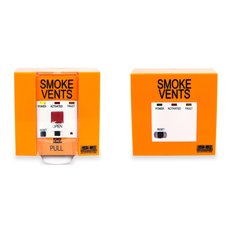
SE Controls OS2 User manual
SE Controls
SE Controls TWIN SECO N 24 25 Manual
SE Controls
SE Controls SECO AKS20000003 Manual

SE Controls
SE Controls SECO Ni AKS20000001 User manual
SE Controls
SE Controls SECO Ni 24 40 Manual
SE Controls
SE Controls SELA U 24 75 Manual
SE Controls
SE Controls Seco Ni 40 Manual
SE Controls
SE Controls SECO Ni Manual
