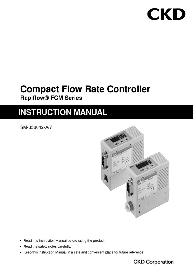
CKD IO-Link FCM Series User manual

New Products
IO-Link Compatible Compact
Flow Rate Controller RAPIFLOW
®
FCM Series
CC-1465A
IO-Link makes it possible!
Predictive maintenance from
a ow rate controller

[Applicable uids/
ow rates]
AIR N2
0.015 to 100 L/min
Weight: Approx. 200 g
Introducing the IO-Link model
IO-Link
Master
Ethernet
Cloud
Plant
Production site
PLC
I/O
Continuous
monitoring alarm
notification
Housing
identification
parameter
change
Features of IO-Link
Digital signal
Constant monitoring via digital data is possible.
Parameter remote control
Parameters can be set and changed via the
network, enabling remote equipment operation.
Housing identification
Models, serial numbers, etc., can be conrmed
on the network.
Data storage The settings can be copied from the master
(scanner), making parameter reconguration
after maintenance obsolete.
Error notification
Device failure and disconnection can be
conrmed.
Connection to fieldbus
It can also be converted to Ethernet networks
and connected, enabling devices to be IoT-ready.
Resin body
Equipped with high-speed
response micro-machined
sensor chip
Rectifying mechanism reduces
pressure loss and improves
reproducibility
[Applicable uids/ow rates]
AIR N2
0.015 to 50 L/min
Ar
0.015 to 50 L/min
O213A CH4
C3H8
0.015 to 10 L/min
H2He
0.06 to 20 L/min
Weight: Approx. 480 g
Stainless steel body
Supports the IoT generation!
Flow rate controller equipped with
predictive maintenance functions
IO-Link is a digital communication standard for sensors/actuators at factory sites. (IEC 61131-9)
Unlike analog communication, it enables the transmission of parameters and event data.

[System abnormality warning
functions]
In addition to self-detection functions
for detecting the deterioration of
sensors and proportional solenoid
valves, abnormalities with peripheral
systems can also be detected.
Outputs an alarm signal via IO-Link.
Compatible with various gases. It can be used in various applications.
Lineup of even lower differential pressure models.
Suitable for controlling burner ame or other ammable gases with low supply pressure.
Applicable uids
Air Nitrogen Argon Oxygen Methane
Propane City gas
Hydrogen
Helium etc.
●Various settings are possible with key operations
and conguration is possible remotely.
• Input method switching
• Preset memory value input
• Flow rate control / forced OFF state switching
●4 preset memory items (conventional type)
➡Increased to 8 items.
● 4 switch output types can be congured and output
simultaneously.
● Directly output accumulated ow value.
System error detection (predictive maintenance)
Compatible with various uids
IO-Link Enhances Conventional Features
Regulator
FCM Filter
IO-Link
Master Filter
clogging
Pressure
drop
Remote
control
Key
operation

Dry
air
0.1 1 10 100
Flow rate (L/min)
N
2
O
2
H2
Flammable gas
Ar
Applicable uids
Liquid crystal
Floating transport system of glass
Semiconductor
Automobiles, other
Flow rate control of argon gas for welding
Glass processing
Burner flame control
Liquid crystal
Flow rate management of ionizer purge gas
Available with a broad flow rate range.
Flow rate control of air is possible.
Wire bonding
Ideal for tension control of wire bonding
that requires high precision.
Ideal for float (non-contact) transportation
of large FPD glass.
Semiconductor
Purge gas flow rate control
Available with a broad flow rate range.
Flow rate control of purge gas can be done.
Foodstuffs Filling and packaging
Ideal for inert gas filling of food packaging, etc.
Control of N2gas in laser oscillator and semiconductor
manufacturing equipment
Available with a broad flow rate range.
Flow rate control of argon gas for welding is possible.
Suitable for controlling burner flame by
allowing low pressure gas supply.
Applications
Used in various elds
RAPIFLOW is available for a wide variety of applications in industries such as machinery,
automobiles, precision components, and cutting-edge elds such as semiconductors and
biotechnology, medical care, foodstuffs, and more.

Applicable uids/ow rate control range
Communication specications
Descriptions Details
Communication protocol IO-Link
Communication protocol version
V1.1
Transmission bit rate COM3 (230.4 kbps)
Port type A
Process data length (input)
10 byte
Descriptions Details
Process data length (output)
4 byte
Min. cycle time 2 ms
Data storage 1k byte
SIO mode support No
RAPIFLOW ® FCM Series Variation
Model No. Applicable
uids
Flow rate control range (L/min) Body material Port size
0.01 0.1 1 10 100
Air
FCM-9500 AI
AIR
Air
N2
Nitrogen
0.015 to 0.5
Resin
SUS
Resin
ø6 push-in
ø8 push-in
SUS
Rc1/4
9/16-18 UNF
FCM-0001 AI 0.03 to 1
FCM-0002 AI 0.06 to 2
FCM-0005 AI 0.15 to 5
FCM-0010 AI 0.3 to 10
FCM-0020 AI 0.6 to 20
FCM-0050 AI 1.5 to 50
FCM-0100 AI (Resin type only) 3 to 100
Gas
FCM-9500 AR
Ar
Argon
0.015 to 0.5 SUS
Rc1/4
9/16-18 UNF
FCM-0001 AR 0.03 to 1
FCM-0002 AR 0.06 to 2
FCM-0005 AR 0.15 to 5
FCM-0010 AR 0.3 to 10
FCM-0020 AR 0.6 to 20
FCM-0050 AR 1.5 to 50
Gas
FCM-9500 O2/LN/C1/C3 O2
Oxygen
13A
City gas
CH4
Methane
C3H8
Propane
0.015 to 0.5 SUS
Rc1/4
9/16-18 UNF
FCM-0001 O2/LN/C1/C3 0.03 to 1
FCM-0002 O2/LN/C1/C3 0.06 to 2
FCM-0005 O2/LN/C1/C3 0.15 to 5
FCM-0010 O2/LN/C1/C3 0.3 to 10
Gas
FCM-0002 H2/HE H2
Hydrogen
He
Helium
0.06 to 2 SUS Rc1/4
9/16-18 UNF
1/4" double
barbed tting
1/4" JXR
male tting
FCM-0005 H2/HE 0.15 to 5
FCM-0010 H2/HE 0.3 to 10
FCM-0020 H2/HE 0.6 to 20

Compact ow rate controller RAPIFLOW
FCM Series
IO-Link
● For air, nitrogen, argon, oxygen, city gas, methane, propane (ow
rate range: 0.5 to 100 L/min)
●
For hydrogen, helium (ow rate range: 0 to 20 L/min)
■FCM Series for air, nitrogen, argon, oxygen, city gas, methane, propane
Specications
Model No.
Descriptions FCM-[*1][*2]-[*3]C
Valve drive method Proportional solenoid valve - When not energized: Closed
Full scale ow rate
AI (Air, nitrogen)
AR (Argon)
O2 (Oxygen) LN (City gas) C1 (Methane) C3 (Propane)
Flow rate range
*1 *1
Standard
9500 500 mL/min ●●●●●●
0001 1 L/min ●●●●●●
0002 2 L/min ●●●●●●
0005 5 L/min ●●●●●●
0010 10 L/min ●●●●●●
0020 20 L/min ● ●
0050 50 L/min ● ●
0100 100 L/min (Resin type only) ●
Low differential pressure type
(Stainless steel only)
L9500 500 mL/min ● ●●●●
L0001 1 L/min ● ●●●●
L0002 2 L/min ● ●●●●
L0005 5 L/min ● ●●●●
L0010 10 L/min ● ●●●●
Applicable uids
*2 *2
AI Compressed air, nitrogen ●
AR Argon ●
O2 Oxygen (Oil-prohibited) ●
LN City gas (13A) *3 ●
C1 Methane (CH4 100%) ●
C3 Propane (C3H8 100%) ●
Port size, body
material *3
H6
ø6 push-in, resin (excluding 50, 100 L/min)
●
H8 ø8 push-in, resin ●
8A RC1/4, stainless steel ●●●●●●
UF 9/16-18UNF, stainless steel ●●●●●●
Control
Control range 3 to 100% F.S.
Response
time
*1 9500 to 0020 Within 0.5 sec. to setting ±5% F.S. (TYP.)
0050 to 0100 Within 1 sec. to setting ±5% F.S. (TYP.)
Accuracy Within ±3% F.S.
Repeatability Within ±1% F.S.
Temperature characteristics Within ±0.2% F.S./ °C (base temperature 25 °C)
Pressure characteristics Within ±1% F.S. per 98 kPa (standard differential pressure reference)
Pressure
Standard differential pressure *4
Refer to the separate table
Working pressure differential
*5 Refer to the separate table
Max. working pressure *5 Refer to the separate table
Proof
pressure *2 H6/H8 490 kPa
8A/UF 980 kPa
Operating ambient temperature,
operating ambient humidity 0 to 50 °C, 90% RH or less (non-condensing)
I/O Input signal C IO-Link
Flow rate
display
Display method 7-segment LED 3-digit, indicator accuracy: control accuracy ±1 digit
Display range, display resolution
Refer to the separate table
Integrating functions Refer to the separate table
Power
supply
Power supply voltage 24 VDC ± 10% (stabilized power supply with ripple rate 1% or less)
Current consumption *6 200 mA or less (Port type A)
Mounting orientation Unrestricted in vertical/horizontal direction
Wetted section
materials *3 H6/H8 Polyamide resin, uoro rubber, stainless steel, alumina, semiconductor silicon, soldering
8A/UF Stainless steel, uoro rubber, alumina, semiconductor silicon, soldering
Weight *3 H6/H8 Approx. 200 g
8A/UF Approx. 480 g
Degree of protection IEC standards IP40 or equivalent
Protection circuit *7 Power supply reverse connection protection
EMC Directive EN55011, EN61000-6-2, EN61000-4-2/3/4/6/8
1

*1: The value converted to volumetric ow rate at standard condition (20 °C 1 barometric pressure (101 kPa) relative humidity 65%). Full scale stands for max.
scale ow rate in the ow rate range.
*2: Use dry gas which does not contain corrosive elements such as chlorine, sulfur or acids, and which is clean and does not contain dust or oil mist.
When using compressed air, use clean air compliant with JIS B8392-1: 2012 (ISO 8573-1: 2010) [1: 1: 1 to 1: 6: 2]. Compressed air from the compressor
contains drainage-water, oil oxide, foreign substances, etc. To maintain the function of this product, install a lter, air dryer (min. pressure dew point 10˚C or
less), and oil mist lter (max. oil concentration 0.1 mg/m3) on the primary side (upstream side) of this product.
[Recommended circuit]
[Recommended device]
Air lter: F Series
Oil mist lter: M Series
*3: The value for city gas 13A is a value for methane (CH4) 88% gas generated from LNG.
*4: Standard differential pressure is the differential pressure when this product is calibrated. (Secondary side released to atmosphere)
*5: Working pressure differential is the differential pressure required for normal operation of this product. Note that the values depend on the ow rate range and
applicable product(s) uids.
The min. value of the working pressure differential is the differential pressure required for the full scale ow rate to ow when secondary
side is released to atmosphere.
The max. working pressure (max. value of working pressure differential) is the max. value of primary side pressure. If more
pressure is applied, control may become unstable, or the max. ow rate may not be controllable.
*6: Ensure that the current supply capacity per IO-Link master port is sufcient.
*7: This product's protection circuit is effective only for specic misconnections. It does not provide protection for all misconnections.
*8: The low pressure line (1 to 2.5kPa) of city gas is outside the working pressure differential range.
*9: The accumulated ow is a reference value. It is reset when the power is turned OFF
*10: The valve inside this product cannot be used as a stop valve requiring zero leakage. Slight leakage is allowed for in the specications.
FCM Series
Specications
Display, integrating functions
(Low differential pressure model)
(Standard model)
Standard differential pressure, working pressure differential *4, 5
Pressure
Flow rate range *1
9500 0001 0002 0005 0010 0020 0050 0100
Applicable uids *2
AI
Standard differential pressure (kPa)
50 100 100 100 100 150 200 300
Working pressure differential (kPa)
20 to 150 50 to 200 50 to 250 50 to 250 50 to 250 100 to 300 150 to 300 250 to 350
Max. working pressure (kPa)
150 200 250 250 250 300 300 350
AR
Standard differential pressure (kPa)
50 100 100 100 100 150 200
Working pressure differential (kPa)
20 to 150 50 to 200 50 to 250 50 to 250 50 to 250 100 to 300 150 to 300
Max. working pressure (kPa)
150 200 250 250 250 300 300
O2
Standard differential pressure (kPa)
50 100 100 100 100
Working pressure differential (kPa)
20 to 150 50 to 200 50 to 250 50 to 250 50 to 250
Max. working pressure (kPa)
150 200 250 250 250
LN/C1
Standard differential pressure (kPa)
50 50 50 50 50
Working pressure differential (kPa)
20 to 150 20 to 150 20 to 150 20 to 150 30 to 150
Max. working pressure (kPa)
150 150 150 150 150
C3
Standard differential pressure (kPa)
50 50 50 50 50
Working pressure differential (kPa)
20 to 150 20 to 150 20 to 150 20 to 150 30 to 150
Max. working pressure (kPa)
150 150 150 150 150
Flow rate range *1
L9500 L0001 L0002 L0005 L0010
Applicable uids *2
AI/O2
LN/C1
C3 *8
Standard differential pressure (kPa)
20 20 20 20 20
Working pressure differential (kPa)
5 to 50 5 to 50 5 to 50 5 to 50 10 to 50
Max. working pressure (kPa)
50 50 50 50 50
Flow rate range *1
9500
L9500
0001
L0001
0002
L0002
0005
L0005
0010
L0010 0020 0050 0100
Flow rate
display
Display range
0 to 500 mL/min
0.00 to 1.00 L/min 0.00 to 2.00 L/min 0.00 to 5.00 L/min
0.0 to 10.0 L/min 0.0 to 20.0 L/min 0.0 to 50.0 L/min
0 to 100 L/min
Display resolution 1 mL/min 0.01 L/min 0.01 L/min 0.01 L/min 0.1 L/min 0.1 L/min 0.1 L/min 1 L/min
Integrating
functions *9
Display range 999999 mL 9999.99 L 9999.99 L 9999.99 L 99999.9 L 99999.9 L 99999.9 L 999999 L
Display resolution 1 mL 0.01 L 0.01 L 0.01 L 0.1 L 0.1 L 0.1 L 1 L
Pulse output rate 5 mL 0.01 L 0.02 L 0.05 L 0.1 L 0.2 L 0.5 L 1 L
Oil mist lter
(Micro alescer)
RegulatorAir dryer
Filter
FCM SeriesPneumatic
source
2
FCM Series
■FCM Series for hydrogen, helium
Specications
Model No.
Descriptions FCM-[*1][*2]-[*3]C
Valve drive method Proportional solenoid valve - When not energized: Closed
Full scale ow rate H2 (Hydrogen) HE (Helium)
Flow rate range
*1 *1
0002 2 L/min ● ●
0005 5 L/min ● ●
0010 10 L/min ● ●
0020 20 L/min ● ●
Applicable uids
*2 *2 H2 Hydrogen ●
HE Helium ●
Port size *3
8A RC1/4 (stainless steel) ● ●
UF 9/16-18UNF (stainless steel) ● ●
4S 1/4" double barbed tting (stainless steel) ● ●
4RM 1/4" JXR male tting (stainless steel) ● ●
Control
Control range 3 to 100% F.S.
Response time
Within 0.5 sec. to setting ±5% F.S. (TYP.)
Accuracy Within ±3% F.S.
Repeatability Within ±1% F.S.
Temperature characteristics Within ±0.2% F.S./°C (base temperature 25°C)
Pressure characteristics Within ±1% F.S. per 98 kPa (standard differential pressure reference)
Pressure
Standard differential pressure *3
Refer to the separate table
Working pressure differential *4
Refer to the separate table
Max. working pressure *4 Refer to the separate table
Proof pressure 980 kPa
Operating ambient temperature,
operating ambient humidity 0 to 50°C, 90% RH or less (non-condensing)
External leakage 1×10⁻⁶ Pa·m3/s (helium leakage rate) or less
I/O Input signal C IO-Link
Flow rate
display
Display method 7-segment LED 3-digit, indicator accuracy: control accuracy ±1 digit
Display range, display
resolution Refer to the separate table
Integrating functions Refer to the separate table
Power
supply
Power supply voltage 24 VDC ± 10% (stabilized power supply with ripple rate 1% or less)
Current consumption *5 220 mA or less (Port type A)
Mounting orientation Unrestricted in vertical/horizontal direction
Wetted section materials Stainless steel, uoro rubber, alumina, semiconductor silicon, soldering
Weight *3 8A/UF Approx. 480 g
4S/4RM Approx. 560 g
Degree of protection IEC standards IP40 or equivalent
Protection circuit *6 Power supply reverse connection protection
EMC Directive EN55011, EN61000-6-2, EN61000-4-2/3/4/6/8
3

Flow rate range *1
0002 0005 0010 0020
Applicable uids *2
H2
Standard differential pressure (kPa)
20 50 50 50
Working pressure differential (kPa)
10 to 50 30 to 80 30 to 80 30 to 80
Max. working pressure (kPa)
50 80 80 80
HE
Standard differential pressure (kPa)
50 100 100 100
Working pressure differential (kPa)
20 to 100 50 to 150 50 to 150 50 to 150
Max. working pressure(kPa)
100 150 150 150
Flow rate range *1
0002 0005 0010 0020
Flow rate
display
Display range 0.00 to 2.00 L/min 0.00 to 5.00 L/min 0.0 to 10.0 L/min 0.0 to 20.0 L/min
Display resolution 0.01 L/min 0.01 L/min 0.1 L/min 0.1 L/min
Integrating
functions *7
Display range 9999.99 L 9999.99 L 99999.9 L 99999.9 L
Display resolution 0.01 L 0.01 L 0.1 L 0.1 L
Pulse output rate 0.02 L 0.05 L 0.1 L 0.2 L
*1: Flow rate converted to volumetric ow rate at 20°C, 1 barometric pressure (101 kPa). Full scale stands for max. scale ow rate in the ow rate range.
*2: Use dry gas which does not contain corrosive elements such as chlorine, sulfur or acids, and which is clean and does not contain dust or oil mist.
*3: Standard differential pressure is the differential pressure when this product is calibrated. (Secondary side released to atmosphere)
*4: Working pressure differential is the differential pressure required for normal operation of this product. Note that the values depend on the ow rate range and
applicable uids. The min. value of the working pressure differential is the differential pressure required for the full scale ow rate to ow when secondary side
is released to atmosphere. The max. working pressure (max. value of working pressure differential) is the max. value of primary side pressure. If more pressure
is applied, control may become unstable, or the max. ow rate may not be controllable.
*5: Ensure that the current supply capacity per IO-Link master port is sufcient.
*6: This product's protection circuit is effective only for specic misconnections. It does not provide protection for all misconnections.
*7: The accumulated ow is a reference value. It is reset when the power is turned OFF.
*8: The valve inside this product cannot be used as a stop valve requiring zero leakage. Slight leakage is allowed for in the specications.
Display, integrating functions
Standard differential pressure, Working pressure differential
Pressure
FCM Series
Specications
4

■Air, nitrogen, argon, oxygen, city gas, methane, propane
Flow rate range
H6AI
Discrete option model No.
[Example of model No.]
FCM-0001AI-H8CRSBK
●
AFlow rate range : 0 to 1 L/min
●
B Applicable uids : Compressed air, nitrogen
●
C
Port size, body material
:
Push-in (ø8), resin body
●
DInput signal : IO-Link
●
EDisplay direction : Reverse direction
●
FCable :
Straight (female), straight (male) 3 m
●
GBracket : Bracket
●
H Traceability : With inspection certication
MS3FCM
C TBSR
9500FCM
Model No.
How to order
Code Content
MS3
Straight (female), straight (male) 3 m
ML3
L type (female) / straight (male) 3 m
MM3 One side straight (female) 3 m
LB1 Bracket
FCM Series
A
Traceability
H
Bracket
G
Code Content
AFlow rate range
Applicable uids AI AR O2 LN C1 C3
9500
Standard differential pressure model
0 to 0.5 L/min
●●●●●●
0001 0 to 1 L/min ●●●●●●
0002 0 to 2 L/min ●●●●●●
0005 0 to 5 L/min ●●●●●●
0010
0 to 10 L/min
●●●●●●
0020
0 to 20 L/min
● ●
0050
0 to 50 L/min
● ●
0100
0 to 100 L/min
(resin body only)
●
L9500
Low differential pressure model
(Stainless steel only)
0 to 0.5 L/min
● ● ● ● ●
L0001 0 to 1 L/min ● ● ● ● ●
L0002 0 to 2 L/min ● ● ● ● ●
L0005 0 to 5 L/min ● ● ● ● ●
L0010
0 to 10 L/min
● ● ● ● ●
BApplicable uids
AI Compressed air, nitrogen gas
AR Argon
O2 Oxygen (oil-prohibited specications)
LN City gas (13A)
C1 Methane (CH4)
C3 Propane (C3H8)
C
Port size, body material
Port size, body material AI AR O2 LN C1 C3
H6
Push-in (ø6), resin body (Excluding
ow rate ranges of 50 or 100 L/min)
●
H8
Push-in (ø8), resin body
●
8A
Rc1/4, stainless steel body
●●●●●●
UF *1
9/16-18UNF, stainless steel body
●●●●●●
DInput signal
CIO-Link
EDisplay direction
Blank Forward direction
RReverse direction
FCable *2
Blank None
SStraight (female), straight (male) 3 m
LL type (female) / straight (male) 3 m
MOne side straight (female) 3 m
GBracket *2
Blank None
BBracket
HTraceability *2
Blank None
TTraceability certication with series variation diagram
and inspection certication
KWith inspection certication
*1: Refer to dimensions on page 7 for the shape of 9/16-18UNF threads.
*2:
If (HE), (TO), (CHI) is selected then it will be attached to the delivered product.
Applicable uids
B
C
D
E
Cable
F
Input signal
Port size, body
material
Display
direction
5

■For hydrogen, helium
8AH2
Discrete option model No.
[Example of model No.]
FCM-0002H2-8ACRSBK
●
AFlow rate range : 0 to 2 L/min
●
B Applicable uids : Hydrogen
●
CPort size : Rc1/4
●
DInput signal : IO-Link
●
EDisplay direction : Reverse direction
●
FCable : Straight (female), straight (male) 3 m
●
GBracket : Bracket
●
H Traceability : With inspection certication
MS3FCM
C TBSR
0002FCM
Model No.
How to order
Code Content
MS3
Straight (female), straight (male) 3 m
ML3
L type (female) / straight (male) 3 m
MM3 One side straight (female) 3 m
LB1 Bracket
Traceability
H
Bracket
G
Flow rate range
A
B
D
Port size
C
E
Code Content
AFlow rate range
Applicable uids H2 HE
0002 0 to 2 L/min ● ●
0005 0 to 5 L/min ● ●
0010 0 to 10 L/min ● ●
0020 0 to 20 L/min ● ●
B Applicable uids
H2 Hydrogen
HE Helium
CPort size
Port size H2 HE
8A Rc1/4 ● ●
UF 9/16-18UNF ● ●
4S 1/4" double
barbed tting ● ●
4RM 1/4" JXR
male tting ● ●
D Input signal
CIO-Link
EDisplay direction
Blank Forward direction
RReverse direction
FCable *2
Blank None
SStraight (female), straight (male) 3 m
LL type (female) / straight (male) 3 m
MOne side straight (female) 3 m
GBracket *2
Blank None
BBracket
HTraceability *2
Blank None
TTraceability certication with series variation diagram
and inspection certication
KWith inspection certication
*1: Refer to dimensions on page 7 for the shape of 9/16-18UNF threads.
*2: If (HE), (TO), (CHI) is selected then it will be attached to the delivered
product.
FCM Series
How to order
Applicable uids
Input signal
Display direction
Cable
F
6

FCM Series
Dimensions
Model No.: FCM-□-H6C/H8C□
Port size: Push-in (ø6) or (ø8)
Model No.: FCM-□-8AC/UFC□
Port size: Rc1/4 or 9/16-18UNF
Model No. Fitting
Dimension
(A)
FCM-□-H6C□ø6 push-in 84
FCM-□-H8C□ø8 push-in 85
M12, 4-pin connector
2-ø6 push-in tting or
2-ø8 push-in tting
2-Rc1/4 or
2-9/16-18UNF
Port size
Port size
2-M3 depth 5
2-M3 depth 5
Note: The cable draw direction is xed in the orientation shown in the gure.
For FCM-□-□CR□, display direction is reversed.
FCM-ML3 (Optional)
FCM-MS3, MM3
(Optional)
FCM-MS3, MM3
(Optional)
45.9
45.9
12
12
16
16
(31)
(31)
24.5
24.5
1
1
(41)
(41)
30
30
15
15
70
70
70
70
(A)
11
11
30
30
Seal surface
45°
12°
9/16-18UNF
Effective thread depth 11.5
Mesh lter
9/16-18UNF
11.5
15.25
ø15.6
2.5
Note: The cable draw direction is xed in the orientation shown in the gure.
For FCM-□-□CR□, display direction is reversed.
FCM-ML3 (Optional)
7

Dimensions
Model No.: FCM-□-4SC
Port size: 1/4" double barbed tting
FCM Series
Dimensions
Model No.: FCM-□-4RMC
Port size: 1/4" JXR male tting
M12, 4-pin connector
2-1/4" double
barbed tting
2-1/4" JXR
male tting
Port size
Port size
2-M3 depth 5
2-M3 depth 5
Note: The cable draw direction is xed in the orientation shown in the gure.
For FCM-□-□CR□, display direction is reversed.
FCM-ML3 (Optional)
FCM-ML3 (Optional)
FCM-MS3, MM3
(Optional)
FCM-MS3, MM3
(Optional)
45.9
45.9
12
12
16
16
(31)
(31)
24.5
24.5
1
1
(41)
(41)
30
30
15
15
70
70
70
70
(121.4)
(117.8)
11
11
30
30
8

Dedicated bracket (oor mounted)
Discrete model No.: FCM-LB1
FCM Series
Cable optional dimensions
●Cable option (M12 straight (female), M12 straight (male))
Discrete model No.: FCM-MS3
●Cable option (M12 L type (female), M12 straight (male))
Discrete model No.: FCM-ML3
●Cable option (M12 one side straight (female))
Discrete model No.: FCM-MM3
* Insulate wires so that they do not contact other wires.
Material : Steel
Weight : 28 g
Cable color Applications
Brown L + (24 DC)
White N.C. *
Blue L-(GND)
Black C(IO-Link)
13
ø6ø4ø6
30
1
5
4-R3
4-ø3.5
4-3.5
8-R1.75
4-6
65
3000
3000
3000
30
50
40
15
9

FCM Series
Wiring method
Wiring method
Wiring method
Terminal No. Option cable
color Name
①Brown L+ (24 VDC)
②White N.C.
③Blue L- (GND)
④Black C (IO-Link)
CAUTION: Take care to prevent incorrect wiring.
Main
circuit
①L+ (24 VDC) Brown
③(Blue)
②(White)
①(Brown)
④(Black)
②N.C. White
③L-(GND) Blue
④C(IO-Link) Black
FCM (Device) IO-Link master
10

FCM Series
Functions
Compact ow rate controller - About FCM series functions
Function Content
Instantaneous ow rate
display
Displays the instantaneous ow rate.
Instantaneous ow rate values are output to Process Data IN.
Set ow rate output Process Data IN outputs the current ow rate setting.
• Integrating functions
• Accumulated ow auto
cutoff function (F5)
Integrates the ow rate. As well as accumulated ow display, it has the following functions.
• Process Data OUT can be used to control the start/stop/reset of integrating functions
• Integrated ow rate values are output to Process Data IN
• Closes the solenoid valve when the value reaches the set accumulated ow
• Accumulated pulse output (switch output 3)
• Switch ON using the accumulated ow rate (switch output 4)
How to reset the integrated value
• Process Data OUT, key input
Normal Mode Input
Function (F1) Process Data OUT can be used to set an arbitrary ow rate.
Direct memory function
(F1) Target value can be entered by key.
Preset input function (F1) 8 items can be specied arbitrarily for the ow rate (IO-Link parameter, key input), which can be controlled with the 3bits from
Process Data OUT.
Error display function
Capable of displaying error state. Other than the error display, the following functions are available.
• Process Data IN error signal output during an error
• Process Data IN error code output during an error
• Stops control automatically when an error occurs
Normal operation output Outputs a signal to Process Data IN when operating normally (without an error).
Switch output function
(F4)
The following switch functions can be congured individually.
• Tolerance mode: Turns the switch ON when the value is within tolerance against the control target value (freely congurable)
• Switch output 2 (designated range mode): Turns the switch ON when the value is within the designated ow rate range
• Switch output 3 (integrated pulse): Outputs the integrated pulse when performing integration
• Switch output 4 (ON at set integration or higher): Turns the switch ON when the value reaches the set accumulated ow
NO (normally open) and NC (normally closed) output modes can be congured for each switch output.
Zero point adjustment
(F7) Adjusts the zero point of ow rate output.
Auto-power OFF (F3) Turns the ow rate display OFF if a key is not operated for approx. 1 minute (control does not stop with auto-power OFF function).
Enables energy-saving operation.
Error auto shut-off (F6) Stops control when an error occurs, fully closes valves, and turns error output ON.
Key lock Disables setting changes by key operation to avoid incorrect operation.
Reset setting Returns the settings to default.
Control error threshold
setting The control error judgment threshold can be set with the IO-Link parameter. (Default: ±20%F.S.)
Communication error
operation and settings (F8)
The operation of the product when a communication error occurs can be set from HOLD (holds the set value before the error occurs) /
CLEAR (valve fully closed) / VALVE OPEN (valve fully open).
Output when starting Displays the total start time from the start of use. This time is not reset even if the power turns OFF. (Also not reset when using
the reset setting.)
Data storage function
Uploading set values to the master and downloading set values from the master are possible. (Can be copied by the same model No.)
* Input signal zero/span adjustment function (F2) cannot be used with IO-Link types.
<Switch output 2: Designated range mode>
H (Upper limit side)
L (Lower limit side)
Output Output
H (+ tolerance side)
Input signal set value
L (- tolerance side)
OFF
ON
OFF
ON
<Switch output 1: Tolerance mode>
OFF
Approx. 50 msec
ON
<Switch output 3: Accumulated pulse>
OFF
ON
<Switch output 4: ON above set integrated value>
Set integrated value
Refer to the display, integrating functions on P2
and P4 for details about pulse output rates.
11

●
Displays instantaneous ow rate display and function setting
details during RUN mode (instantaneous ow rate display).
* The setting mode No. and setting details are displayed
when displaying details of function settings.
●
The values are displayed when setting each piece of data.
●Error code No. is displayed at the time of error display.
3-digit number LED display (green)
FCM Series
Operation mode
Names and functions of display/operation section
● "F" is displayed when conrming the
function setting.
●"-" is lit when switch output is ON.
* Does not blink at integrated pulse output.
●"E" is lit when error output is ON.
Output display (Red)
*
When function settings have upper/lower limits or when high-order
digit or low-order digit of accumulated ow display is indicated,
or will be displayed.
[Disabled display]
[Error output]
[Setting details display]
[At instantaneous
ow rate display]
Setting mode No.Setting mode No.
Flow rate 110% F.S. or more: Hi
Setting details
Code No.
Setting details
●Used to select the digit of the values.
●Used to reset from forced OFF when performing
forced OFF (control stop).
Shift key (OFF key)
●Used to count down values.
●Used to set the key lock.
+ Key (DOWN key)
● Used to conrm the value.
●Used to release the key lock.
●Used to reset accumulation.
(Accumulated ow displayed)
+ Key (ENT key)
● Used to conrm the setting mode.
● Used to conrm the setting item.
●Used to change to the integration display.
●Blinks during IO-Link
communication.
●Lights when a communication
error occurs.
Key
Power lamp (red dot)
●Used for resetting settings
(initialization).
Key
●Used to count up values.
●Used to change the setting mode.
●Used to change the settings item.
UP key (MODE key)
+
12

FCM Series
Category Display processing Error display
Control processing
(Solenoid valve
operation)
Countermeasure
Error
The power voltage is not
within the rating.
Detection level: 19.5 V or less
Depending on F6
setting. (*2)
• Set the power voltage within the rated
range, then turn the power ON again.
Error
The input signal exceeded the
rating range.
Detection level: 110% F.S. or
more
Depending on F6
setting. (*2)
• Set the input signal to within the rated
range.
Error An error occurred during
EEPROM reading or writing
Flow rate control
stop.
• Turn power ON again.
• Replace the device.
Error An error occurred during
memory reading or writing
Flow rate control
stop.
• Turn power ON again.
• Replace the device.
Error
The ow rate did not reach the
setting value for 5 secs. or
more consecutively.
20% F.S.(*1) or less of the set
value was not attained
Depending on F6
setting. (*2)
• Check the primary pressure and supply
pressure within the rating working
pressure differential, then turn the
power ON again.
•
Check that there are no leaks from
pipes, ttings, or other devices. Correctly
connect, then turn the power ON again.
Error Sensor output failure has
occurred
Flow rate control
stop.
Valve closed.
•
Stop the supply of uid to the device, set
the ow rate setting to zero, and then
turn ON the device power supply again.
• Replace the device.
Error
(*3)
The valve was not forced to
the OFF state during zero
adjustment
Flow rate control
will not stop.
• Force the valve to OFF before
operation.
Error
(*3)
The ow rate exceeds the
zero adjustment range.
(Flow ≥ ±10% F.S.)
Flow rate control
will not stop.
• Check that the primary pressure and
supply pressure are within the rated
working pressure differential, then turn
the power ON again.
Warning
(*3)
The proportional valve used
the limiting value continuously
for over 10 seconds.
7-segment display not used.
Error code is [E10]
Flow rate control
will not stop.
• Check that the primary pressure and
supply pressure are within the rated
working pressure differential, then turn
the power ON again.
• Check that there are no blockages
from pipes, tting, or other devices
then turn the power ON again.
Warning
(*3)
High IO-Link driver
temperature
7-segment display not used.
Error code is [E11]
Flow rate control
will not stop. • Check the usage environment.
*1: IO-Link parameters enable the threshold to be changed.
*2: [F6: Error auto cutoff setting] congured contents determine the operation.
*3: This error only occurs with IO-Link types.
Error code table
Generally, the error resets automatically; however, if it does not do so, hit the emergency stop or
turn OFF the power supply, check and correct the cause of the error as per the following table,
clear the emergency stop and then turn ON the power supply again.
13

FCM Series
Communication specications
* Refer to the SM-A19060 instruction manual for parameter conguration.
* The IO-Link setting le (IODD) can be downloaded from the CKD website (https://www.ckd.co.jp).
Descriptions Details
Communication protocol IO-Link
Communication protocol version 1.1 V
Transmission bit rate COM3 (230.4 kbps)
Port type A
Process data length (input) 10 byte
Process data length (output) 4 byte
Device ID Product ID Remarks
0x216001 FCM-9500-C 500 mL/min Range
0x216002 FCM-0001-C 1 L/min Range
0x216003 FCM-0002-C 2 L/min Range
0x216004 FCM-0005-C 5 L/min Range
0x216005 FCM-0010-C 10 L/min Range
0x216006 FCM-0020-C 20 L/min Range
0x216007 FCM-0050-C 50 L/min Range
0x216008 FCM-0100-C 100 L/min Range
Model No.
Instantaneous ow rate Accumulated ow
Display range Display value ProcessData
output value
Accumulated
display range Display value
FCM-(L)9500*-*C 0 to 500.0 mL/min 0 to 500 0 to 5000 0 to 999999 mL
0 to 999999
FCM-(L)0001*-*C 0.00 to 1.000 L/min 0 to 1.00 0 to 1000
0 to 9999.99 LFCM-(L)0002*-*C 0.00 to 2.000 L/min 0 to 2.00 0 to 2000
FCM-(L)0005*-*C 0.00 to 5.000 L/min 0 to 5.00 0 to 5000
FCM-(L)0010*-*C 0.0 to 10.00 L/min 0 to 10.0 0 to 1000
0 to 99999.9 LFCM-0020*-*C 0.0 to 20.00 L/min 0 to 20.0 0 to 2000
FCM-0050*-*C 0.0 to 50.00 L/min 0 to 50.0 0 to 5000
FCM-0100*-*C 0 to 100.0 L/min 0 to 100 0 to 1000 0 to 999999 L
Descriptions Details
Min. cycle time 2 ms
Data storage 1 kbyte
SIO mode support No
Device ID Refer to table below
Vendor ID 855 (decimal)/357 (hexadecimal)
■ Communication specications
General
■Parameter
Device ID
Table 1 Flow rate range per model
14

FCM Series
Process data IN
PD PD0 PD1
Bit 79 78 77 76 75 74 73 72 71 70 69 68 67 66 65 64
MSB LSB
Data name Integrating ow unit upper byte
Data range 2 byte
Format UInteger16
PD PD2 PD3
Bit 63 62 61 60 59 58 57 56 55 54 53 52 51 50 49 48
MSB LSB
Data name Integrating ow unit lower byte
Data range 2 byte
Format UInteger16
PD PD4 PD5
Bit 47 46 45 44 43 42 41 40 39 38 37 36 35 34 33 32
MSB LSB
Data name Set ow rate *1
Data range 2 byte
Format UInteger16
PD PD6 PD7
Bit 31 30 29 28 27 26 25 24 23 22 21 20 19 18 17 16
MSB LSB
Data name Instantaneous ow rate *2
Data range 2 byte
Format Integer16
PD PD8 PD9
Bit 15 14 13 12 11 10 9 8 7 6 5 4 3 2 1 0
Data name Error
WARNING
Normal
operation
-Switch output *3 MSB LSB Input setting
*4
Accumulated
auto cutoff
occurring
Start/stop
4 3 2 1 Error code
Data range True/False 0 to 15 0 to 2 True/False
Format Boolean UInteger4 UInteger2 Boolean
*1: Displays the congured ow rate for the current input setting.
"9999" means "valve fully open". (Refer to the Process data OUT item.)
*2: For instantaneous ow rates a negative value is used to check the shift from the zero point and does not indicate a reverse ow.
Switch output Switch function
1 Tolerance mode
2 Designated range mode
3 Integrated pulse
4 ON at set integration or higher
Input setting Input mode
0 Normal mode (ow rate value)
1 Preset mode (3 bit)
2 Direct memory mode (key operation)
*3 *4
15
This manual suits for next models
29
Table of contents
Other CKD Controllers manuals

CKD
CKD KBX-30E-U Series User manual

CKD
CKD KBX-T5 User manual

CKD
CKD FP Series User manual

CKD
CKD AX1R Series User manual

CKD
CKD FGRC Series User manual

CKD
CKD ESSD Series User manual

CKD
CKD ABSODEX AX1022 User manual

CKD
CKD Rapiflow FCM Series User manual

CKD
CKD ECG Series User manual

CKD
CKD GCKW Series User manual
Popular Controllers manuals by other brands

RESEARCH CONCEPTS
RESEARCH CONCEPTS RC4000 user manual

Emerson
Emerson Fisher easy-Drive 200R instruction manual

Musica
Musica MUSICAVC-70ZS installation instructions

Telecom Behnke
Telecom Behnke BEHNKE-STATION Technical manual

YASKAWA
YASKAWA Motoman DX200 instructions

Velleman
Velleman HQ-Power VDPDMXC146 manual