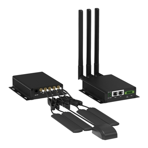
GL-INET Amarok GL-X1200 User manual

1
AMAROK
GL-X1200 is a 3G/4G wireless router with high-performance and stability, to meet with the requirements
of wireless network connection for industrial users. Based on OpenWRT OS, it also offered an integrated
platform of functions extension for developers, Makers, IoT integration and development.
GL-X1200 User Manual

2
Copyright © 2019 Shenzhen Guanglianzhitong Tech Co., Ltd. All rights reserved.
Document Copyrights
No duplication or distribution of this document or any portion thereof shall take place without the express
written permission of Shenzhen Guanglianzhitong Tech Co., Ltd. No part of this manual may be reproduced,
distributed, or transmitted in any form or by any means, electronic or mechanical, for any purpose without
the express written permission of Shenzhen Guanglianzhitong Tech Co., Ltd.
Software Copyrights
The products described in this manual may include copyrighted Shenzhen Guanglianzhitong Tech Co., Ltd.
software. Laws in China and other countries preserve certain exclusive rights of copyrighted software,
including, but not limited to, the exclusive right to copy or reproduce in any form the copyrighted software.
Accordingly, any copyrighted Shenzhen Guanglianzhitong Tech Co., Ltd. software contained in the products
described in this manual may not be copied, reproduced, modified, reverse-engineered, or distributed in any
manner without the express written permission of Shenzhen Guanglianzhitong Tech Co., Ltd.
Trademarks
is trademark of Shenzhen Guanglianzhitong Tech. Co., Ltd., registered in China and other
countries, all other product or service names appearing in this manual are the property of their respective
owners.
Disclaimer
Some features of the product and its accessories described herein rely on the software installed, capacities
and settings of local network, and may not be activated or may be limited by local network operators or
network service providers. Therefore, the descriptions in this manual may not exactly match the purchased
product or its accessories. Shenzhen Guanglianzhitong Tech. Co., Ltd. reserves the right to change or modify
any information or specifications contained in this manual without prior notice and any liability.
Limitation of Liability
All information provided in this manual is provided on "as is" basis without warranties, guarantees or
representations of any kind. Shenzhen Guanglianzhitong Tech. Co., Ltd. hereby expressly disclaims, to the
maximum extent permitted by applicable law, in no case shall Shenzhen Guanglianzhitong Tech. Co., Ltd. be
liable for any special, incidental, indirect, or consequential damages; or lost profits, business, revenue, data,
goodwill or anticipated savings. To the maximum extent permitted by applicable law, in any case, the
maximum compensation of Shenzhen Guanglianzhitong Tech. Co., Ltd for the loss caused by using the
products described in this manual, is the price paid of products (Except for damages in accordance with
applicable law in cases involving personal injury).
Import and export regulations

3
Customers shall comply with all applicable export or import laws and regulations. Customers must obtain all
necessary governmental permits and licenses to export, re-export or import the product (Including but not
limited to software and technical data in products) mentioned in this manual.
Contact
Shenzhen Guanglianzhitong Tech. Co., Ltd
Room 305-306, Skyworth Digital, Songbai road, Shiyan Street, Baoan District, Shenzhen, China
Email:sales@gl-inet.com
Tel: +86-755-86606126
Website: www.gl-inet.com

4
Catalogue
Chapter 1 General Product Introduction ...................................................................................................... 7
1.1 Brief Product Introduction........................................................................................................................ 7
1.2 Technical Specifications............................................................................................................................ 9
1.3 Appearance and dimension.................................................................................................................... 11
1.4 Package list.............................................................................................................................................. 12
1.5 Optional Configuration........................................................................................................................... 15
Chapter 2 Hardware installation...................................................................................................................... 16
2.1 LED light indicator................................................................................................................................... 16
2.2 Reset button ........................................................................................................................................... 17
2.3 USB port .................................................................................................................................................. 17
2.4 Micro-SD card slot................................................................................................................................... 17
2.5 SIM card slot ........................................................................................................................................... 18
2.6 Install antennas....................................................................................................................................... 19
2.7 Install the device..................................................................................................................................... 19
2.7.1 Place on desk ................................................................................................................................... 19
2.7.2 Wall Mounting................................................................................................................................. 20
2.7.3 DIN-Rail Mounting........................................................................................................................... 21
2.7.4 Cabinet Installation.......................................................................................................................... 22
2.8 Ground wire installation......................................................................................................................... 23
2.9 Console port connection......................................................................................................................... 23
2.10 Ethernet cable connection.................................................................................................................... 24
2.11 Power Supply connection..................................................................................................................... 24
2.11.1 Powered by DC adapter................................................................................................................. 24
2.11.2 Powered by PoE Ethernet cable.................................................................................................... 25
2.11.3 POE output..................................................................................................................................... 25
Chapter 3 Login Web UI.................................................................................................................................... 26
3.1 Login........................................................................................................................................................ 26
3.2 Language Setting ..................................................................................................................................... 26
3.3 Set Admin Password................................................................................................................................ 27
3.4 Admin Panel ............................................................................................................................................ 27
Chapter 4 Device Configuration ....................................................................................................................... 28
4.1.1 Brief introduction ............................................................................................................................ 29
4.1.2 Status................................................................................................................................................ 30
4.1.3 Cable................................................................................................................................................. 30

5
4.1.4 Repeater........................................................................................................................................... 31
4.1.5 Tethering.......................................................................................................................................... 35
4.1.6 3G/4G Modem................................................................................................................................. 36
4.2 Wireless................................................................................................................................................... 42
4.2.1 2.4G & 5G WiFi................................................................................................................................. 43
4.2.2 2.4G & 5G Guest WiFi ...................................................................................................................... 44
4.3 Client ....................................................................................................................................................... 46
4.4.1 Online Upgrade................................................................................................................................ 48
4.4.2 Local Upgrade .................................................................................................................................. 49
4.4.3 Automatic Upgrade.......................................................................................................................... 50
4.5 Firewall.................................................................................................................................................... 51
4.5.1 Port Forwarding............................................................................................................................... 51
4.5.2 Turn on Ports.................................................................................................................................... 52
4.5.3 DMZ.................................................................................................................................................. 54
4.6 VPN(No Chinese Version).................................................................................................................. 55
4.6.1 OpenVPN Client ............................................................................................................................... 55
4.6.2 OpenVPN Server .............................................................................................................................. 55
4.6.3 Wireguard Client.............................................................................................................................. 56
4.6.4 Wireguard Server............................................................................................................................. 57
4.6.5 VPN Policies ..................................................................................................................................... 57
4.7 Application Program................................................................................................................................... 58
4.7.2 File sharing....................................................................................................................................... 60
4.7.3 Remote Access................................................................................................................................. 60
4.7.4 Captive Portal................................................................................................................................... 62
4.8 More Settings.......................................................................................................................................... 62
4.8.1 Admin Password .............................................................................................................................. 62
4.8.2 LAN IP............................................................................................................................................... 63
4.8.3 Time Zone......................................................................................................................................... 69
4.8.4 GPS ................................................................................................................................................... 70
4.8.5 MAC address Clone.......................................................................................................................... 73
4.8.6 Self-defined DNS server................................................................................................................... 74
4.8.7 Network mode................................................................................................................................. 75
4.8.8 Reset to factory setting................................................................................................................... 76
4.8.9 Advanced functions ......................................................................................................................... 77
5.1.2 Login by PuTTY................................................................................................................................. 82

6
5.2 Commands introduction......................................................................................................................... 85
5.2.2 ping command ................................................................................................................................. 86
5.2.3 nslookup commmand...................................................................................................................... 87
5.2.4 traceroute command....................................................................................................................... 88
5.2.5 iwinfo command.............................................................................................................................. 89
5.2.9 iptables command ........................................................................................................................... 95

7
Chapter 1 General Product Introduction
1.1 Brief Product Introduction
GL-X1200 is an industrial grade wireless router which offers a solution for 4G network connection with cable
or wirelessly. It is equipped with high-performance QCA9563, @775MHz SoC, with dual 4G/3G/2G modules
as well as dual SIM card slots. It has 4 gigabit LAN ports and 1 gigabit WAN port, dual band, 2x2 MIMO,
IEEE802.11b/g/n and IEEE802.11ac compliable offering up to 1166Mbps Wi-Fi speed(11n 300M+11ac 866M).
It supports 60 devices online at the same time.
It has four full-band external 4G antennas, and two high-gain external Wi-Fi antennas, one built-in GPS/BDS
module and one external antenna accordingly, and one built-in watchdog chipset to ensure a stable operation
of the device.
GL-X1200 is widely applied in fields like Smart Traffic, Smart Manufacturing, Smart business, offering highly
reliable data transmission.
4G Features:
Support dual 4G LTE modules
Support CAT4 (download 150Mbps, upload 50Mbps) or CAT6 (download 300Mbps, upload 50Mbps)
WIFI Features:
Dual band 2.4G & 5G
11n 2x2 + 11ac 2x2,300Mbps(2.4G)+866Mbps(5G)
High-gain dual-band external antennas
Software and Hardware Features:
Built-in dual 4G LTE CAT4 or CAT6 modules
eSIM is supportable
Built-in 128MB NAND-Flash for user’s storage
1*USB2.0, support external USB modem
1*Micro SD/TF card, maximum 128GB storage
Built-in GPS/BDS module
Built-in Watchdog chipset

8
Built-in RTC module
Support RS232 or RS485 serial port (RJ45 port type).
Powered by 12V or 48V DC power supply, or with POE power input (802.3at).
Support 802.3af POE-Out (using 48V DC power in).
Automatically shifting between wireless 4G connection and Ethernet cable connection to keep devices always
online.
Other Features:
Iron enclosure supports stable operation under a temperature from -20 to 55 °C.
Powered by Qualcomm chipset, which has high performance and reliability, low failure rate.
Flexible installation, on desk, wall mounting or DIN-rail mounting (equipped with 35mm rail buckle to match a
35mm rail).

9
1.2 Technical Specifications
Items
Description
Model No.
GL-X1200
CPU
Qualcomm QCA9563,@755MHz
WiFi Chipset
Qualcomm QCA9563 (2.4G) + Qualcomm QCA9886 (5G)
Flash
16MB Nor-FLASH
128MB NAND-FLASH
RAM
128MB DDR
3G/4G module
Support 2x 4G LTE CAT4 or CAT6)
2x micro SIM(3FF) card slot, e-SIM is optional
4G antenna
External full-band antenna (700M ~ 2.7GHz)
WiFi
2.4G+5G dual-band concurrent
802.11b/g/n 2x2 MIMO + 802.11a/n/ac2x2 MU-MIMO
WiFi wireless transmit
2.4GHz 300Mbps
5GHz 866Mbps
WIFI antenna
External dual-band high gain antennas
Wi-Fi Power Output
2.4GHz: 19dBm (11n MCS7 HT40) Max
5GHz: 19dBm (11ac MCS9 HT80) Max
(Output power of the antenna interface, excluding antenna gain )
Wi-Fi Receive Sensitivity
-94dBm((Maximum)
Global Positioning System
Built-in GPS/(BDS) module, external antenna
Watchdog
Internal Watchdog chip
RTC
Internal RTC Module
Ethernet Port
5x 10/100/1000Mbps Ethernet port (1x WAN + 4x LAN)
Console
RS232 or RS485 serial console port (RJ45 connector)
USB port
1x USB2.0 Type-A

10
MicroSD
1x MicroSD (TF) Slot, support maximum 128GB
LED Indicator
Power, PoE output, System, WAN, LAN, 2.4G Wi-Fi, 5G Wi-Fi, 4G Modem #1
signal strength、4G Modem #2 signal strength
(Each 4G module has 3 LED indicate the signal strength)
Reset Button
Press the button more than 8 seconds to reset the device to factory settings.
Power Input
12V/3A or 48V/1A DC input or PoE input (802.3at)
Power Output
Support PoE output (802.3af) when 48V/1A input
Enclosure
Metallic housing case with ground-screws.
Dimension
240*145*40mm (L*W*H, exclude Antenna size)
Weight
1360g (net weight)
Power Consumption
Maximum 11W (Exclude power consumption of external device connected by
USB port)
Temperature
Operation Temperature: -20~55°C ;
(Support extended operating temperature: Powered by PSU -20~60°C;
Powered by POE -40~70°
Limited operation time and may cause performance degradation)
Storage Temperature: -40~70°C

11
1.3 Appearance and dimension
Dimension:240*145*40mm(L*W*H,External Antenna not included)
Front view:
Back view:

12
1.4 Package list
Items
Qty
X1200
1
Dual-band WIFI antenna
2
4G antenna
4 or 2
(If selectCAT6module, it needs 4x External 4G antenna;
If select CAT4 module, it needs 2x External 4G antennas)
GPS antenna
1
Power adapter
1
Ethernet cable
1
35mm DIN rail
1
Rack ear
2
User guide
1
•Dual-band WIFI antenna (inner hole)
•4G antenna (inner needle)

13
•GPS antenna
•Power adapter
This picture is for 48V/1A power adapter, 12V/3A power adapter is optional.
•Ethernet cable
•35mm DIN rail buckle

15
1.5 Optional Configuration
•X1200-D2
4G module: 2 units
Note: 2 * 4G modules are equipped before shipment.
2 *SIM card slots match 2 * 4G modules respectively
•X1200-D1
4G module: 1 unit
Note: 1 * 4G module is equipped before shipment, user could add one more 4G module in necessary.
2 * SIM card slots match 2* 4G modules respectively.
•X1200-S
4G module: 1unit
Note: 1 * 4G module is equipped before shipment.
2 * SIM card slots match one 4G module, and user can choose SIM card either-or via web UI.
Note: Bottom sticker will show device model.

16
Chapter 2 Hardware installation
2.1 LED light indicator
Item
Mark
Color
Description
Power
PWR
Green
Off: Powered off
On: Powered on
PoE output
PoE OUT
Green
Off: No PoE output
On: LAN4 port provides PoE output
System
SYS
Red
Off: System is running normally.
Blinking: Operation System fault (E.g. both WAN port and 4G
are not connected)
Ethernet port
WAN
LAN1~LAN4
Green
Off: No connection.
On: Proper connection.
Blinking: Port has data traffic.
2.4G WIFI
2.4G
Green
Off: WIFI is off.
On: WIFI is on.
Blinking: WIFI has data traffic.
5G WIFI
5G
Green
Off: WIFI is off
On: WIFI is on.
Blinking: WIFI has data traffic
4G signal status
SIM1
SIM2
Green * 3
Off: No signal
1 Green Light on: Poor signal
2 Green Light on: Medium signal
3 Green Light on: Good signal

17
2.2 Reset button
•Press and hold the reset button 8 seconds with a needle after powered on.
•The device will be restarted, and reset to factory settings.
2.3 USB port
•USB2.0 Type-A port.
•Output voltage/current: 5V/500mA.
2.4 Micro-SD card slot
•Push-Push Micro SD(TF)card slot
•With foolproof setting.
•Size of Micro SD card: 15*11mm.
•Max 128GB Micro SD card supportable.

18
2.5 SIM card slot
Insert or remove SIM card
•Press the button which next to the SIM card slot with a needle to pop up the SIM card tray.
•Insert or remove the SIM card.
•Standard size of SIM card should be 25*15mm.
•With foolproof setting.
•Press in the SIM card tray.
•Finished.
Note:
•Keep the SIM card away from electromagnetic field to avoid info. damaging of SIM card.
•Do not bend or scratch SIM card.
•Make sure to power off device when insert or remove SIM card.

19
2.6 Install antennas
Install 4G antennas.
•SMA type (inner needle), full-band antenna, support 700MHz to 2.7GHz.
•Install external 4G antenna on the 4G antenna interface and tighten it.
•MAIN1 and AUX1 antennas (marked red in above picture) match 4G module 1. MAIN2 and AUX2 antennas
(marked deepred in above picture) match 4G module 2.
Install WiFi antennas.
•SMA type (inner hole), dual-band antenna, supports 2.4GHz and 5GHz
•Install external WIFI antenna on the WIFI antenna interface (marked blue in above picture) and tighten it.
Install GPS/BDS antenna optional.
•SMA type (inner needle).
•Install GPS/ BDS antenna on the GPS/BDS antenna interface (marked green in above picture) and tighten it.
2.7 Install the device
It supports placing on desk, wall-mounted and 35mm DIN-rail installation
2.7.1 Place on desk
•Place device on clean and flat desktop

20
•Adjust the position of device and ensure that the left and right sides have a more than 20mm space to
radiate heat.
2.7.2 Wall Mounting
Steps as below:
•Install two fixing screws on the load plane (wall or cabinet).
•The distance of two wall mounting holes is 140mm, and the head diameter of fixed screw isφ5-φ7.3mm. It
is recommended to use M3~M3.5 self-tapping countersunk screw.
•Hang the wall hole (on the back of device) in the two fixing screws.
Note:
•Select firm and smooth load plane which could support the weight of the device and its related
accessories.
•Ensure good stability and ground connection of wall-mounted carrier.
•Do not place the device in humid environment to prevent water vapor or moisture.
Table of contents
Other GL-INET Network Router manuals

GL-INET
GL-INET GL-MiFi Manual

GL-INET
GL-INET Convexa-B User manual

GL-INET
GL-INET GL-B1300 User manual

GL-INET
GL-INET GL-AX1800 User manual

GL-INET
GL-INET Opal User manual

GL-INET
GL-INET GL-MiFi User manual

GL-INET
GL-INET GL-MT300N-V2 Series User manual

GL-INET
GL-INET GL-USB150 User manual

GL-INET
GL-INET GL-AXT1800 User manual

GL-INET
GL-INET GL-X300B User manual
Popular Network Router manuals by other brands

ANTAIRA
ANTAIRA LMP-0602-24-V2 Series Quick installation guide

Efficient Networks
Efficient Networks SpeedStream 5400 Series Product features

NetComm
NetComm Gateway NB6-QSG Connection guide

Tenda
Tenda Nova MW6 Quick installation guide

Theta Digital
Theta Digital Casablanca III HD owner's manual

Foundry Networks
Foundry Networks AR1208 user guide