Glasco UV GUV-7 Manual

March 2009
ULTRAVIOLET WATER DISINFECTION SYSTEM
OPERATION & MAINTENANCE MANUAL
GUV SERIES UV System
GUV-7, GUV-10, GUV-15, GUV-20
Use the attached chart to record lamp changes to the system:
Lamp Change Date
Lamp Change Date
INSTALL DATE:

March 2009
You should have received the following:
REPLACEMENT PARTS LIST
MODEL
Lamp #
Quartz #
Ballast #
Orings
Compression
Fittings
GUV-7
#1 L-501414
#1 Q-532017
#1 P-78PIBP
#1 M-75214O
#1 M-001RCN
GUV-10
#1 L-524414
#1 Q-532017
#1 E-40HOIB
#1 M-75214O
#1 M-001RCN
GUV-15
#1 L-050433
#1 Q-521035
#1 E-361GUB
#1 M-75214O
#1 M-001RCN
GUV-20
#1 L-024433
#1 Q-521035
#1 E-33120B
#1 M-75214O
#1 M-001RCN
1. Your Disinfection Unit – Pre-Installation
Your Ultraviolet (UV) water disinfection system has been tested at Glasco’s manufacturing facility. The unit has been
hydrostatically pressure-tested to 100 psi. In some cases, a small amount of water may remain in the vessel. In order to
insure that the unit works at optimum performance, please follow the instructions outlined in this manual.

August 2009
1.1. Warning
UV light is harmful to your eyes and skin. Do not look directly into the light. Always unplug (disconnect power) your
unit before installing or removing a lamp. Your unit may have a green LED light that indicates that the lamp is
operating and the unit has an audible alarm that will sound in the event of lamp failure. If the LED goes out, contact
your dealer for service. If your unit has an audible alarm and it goes off, contact your dealer.
Since the unit is run by electricity, please remember to disconnect all power before servicing the equipment. Failure to
do so may result in serious injury or death.
When handling lamps and quartz, use gloves to prevent them from becoming dirty. If they do, wipe them with alcohol.
1.2. Your Water Supply
Glasco recommends that trained professionals test and maintain your water supply. In addition to testing the water to
see if UV is appropriate, we recommend pre-filtering systems (softeners, carbon or reverse osmosis) to help remove
tastes, odors, minerals and cysts.
1.3. UV Effectiveness
Your disinfection unit needs to be maintained. Change your lamp on a yearly basis and insure that the quartz sleeve is
cleaned on a regular basis.
Failure to do periodic maintenance will impact your unit’s effectiveness.
1.4. Flow Rate
Your unit has been designed to accommodate a certain flow rate. In order to work effectively, you may need to install a
flow control device. This device attaches to the inlet and controls the water that enters the system. Note: your system
may have come with a flow controller.
Failure to use a flow control (available at most plumbing supply stores) may reduce the effectiveness of your
disinfection unit.
1.5. Inspection
Insure that lamps and quartz have not been broken. We recommend that you use gloves when handling lamps and
quartz sleeves to prevent them from becoming dirty. Dirt and skin oils will impact the UV output.
A warranty sheet has been included. Please fill out the warranty and send back to manufacturer or dealer. This
warrantees the chamber for 7 years and electrical components for 1-year.
1.6. Electrical Requirements
The electronics have been designed to work with standard power supplies. Since the unit is susceptible to power
fluctuations, we recommend that the system be kept off any lines where there are surges. This includes pumps or
motors. If there are fluctuations, please use a surge suppressor. Systems will come with plugs, which require no “hard
wiring”. Please look at the outside of the electrical “box” for Voltage, Cycle and AMP draw.
1.7. Location of Unit
UV disinfection works best when it is installed closest to point of use. When installing, remember that you will need to
be able to remove lamps and quartz as part of a maintenance schedule. Allow yourself enough room to accomplish
these tasks. Unit can be mounted vertically or horizontally. Inlet and outlet can face up or down.

August 2009
Step
Action
Diagram
1
Use # 10 screws (not included)
to mount clips (M-2500MC) to
wall.
Note: On GUV-15/20 four mounting
clips are included. Two clips are to
be mounted two inches apart, and
the remaining clips are to be
mounted directly below them 2”
apart.
2
Open the worm gear clamps
(M-0203WC) completely and
then thread through mounting
clips
(M-2500MC).
Note: On GUV-15/20 thread worm
gear clamp (M-0203WC) through
both mounting clips that are
installed parallel to each other.
3
Tighten worm gear clamps
(M-0203WC) over UV unit until
snug.

August 2009
4
UV unit may be mounted
vertically or horizontally. UV
units inlet port may be rotated
180 degrees. If your system has
been modified with a port do not
install with the port facing
down.
2. Your Disinfection Unit – Installation
If you are attempting to install the unit by yourself and you have questions, please call your water quality or plumbing
professional. Improper installation can cause potential water damage to your property and can also reduce the effectiveness of
the UV disinfection system.
2.1. Recommended Supplies
Before getting started, you will need the following:
•Screws to bolt the unit into place
•Teflon tape to insure quality sealing
•Shutoff values for both the inlet and outlet
•Unions before and after the unit
•Flow control (from dealer or plumbing supply house) Note: many units come with this as a standard
accessory. It looks like a brass disk with a rubber insert. This will be press fit into the inlet and outlet.
2.2. Plumbing
Your unit may be installed under the sink or where the water enters the building. In either case, we recommend that
shutoff valves be installed before the inlet and after the outlet. This allows for easier yearly servicing and allows you to
shut off the water supply if you have a problem with the unit.
A damaged quartz sleeve can cause a potential leaking problem. An unchecked leak can lead to severe flooding.
2.3. Quartz for Close-ended Units (creating a watertight unit)
A sealed unit has one opening for the lamp and quartz to go into. The quartz has a dome on one end like a test tube.
Once the unit has been secured and the piping connections have been made, it is time to install the quartz sleeve.
The unit will have come with a compression nut that is in place and holds an O-ring. Remove the nut and the O-ring.
Insert the dome end of the quartz into the unit. Guide the quartz through the unit until it rests at the end in a spring.
Once in the spring, you can screw in the compression nut (make sure that the O-ring is properly positioned in the nut).
Create a tight seal, but not too tight as you may crack the quartz sleeve.
Now that it is in place, you can test the unit to see if it is watertight. Slowly pressurize the unit by allowing water to run
through the unit for five minutes. As this is happening, check to see if the seal is dry. If it is not, you will need to redo
the seal. If it is dry, you are prepared to install the lamp.
2.4 Installing the Lamp
Carefully slide the lamp into the quartz (dropping the lamp can break the quartz). Once it is in place, connect the lamp
to the socket. When you have done that, tighten the cap to the nut and then plug in the unit.

August 2009
3. Maintenance
As noted in this manual, your lamp needs to be replaced on a yearly basis the quartz cleaned on a more frequent basis.
The quartz may have “build up” on it. If it does, clean it with soap and water. If the quartz is stained, use a product like
CLR or LimeAway (both available at the grocery store).
When you remove the quartz, please follow the same instructions as above.
Track you maintenance record on the front page of this manual.
4. Operation Status and Alarms - Basic
The unit will have come with an audible and or visual lamp status alarm. In the event of a lamp out, the audible alarm will
sound. If the unit has a visual alarm (Green light aka LED indicates lamp is on), the LED will go off when the lamp goes off.
If this is the case, have your water professional check to see if the lamp needs to be replaced. When alarming, the water
may not be safe to drink.
If the lamp is working, suspect that the alarm board has been damaged and is in need of repair.
If you have to access the BCC (Ballast control center) loosen the strain relief on the power cord and pull the base of the box
towards the lamp harness.
GUV-10, GUV-15, GUV-20 BCC
Lamp Harness
Loosen strain relief prior to
pulling out BCC base board

August 2009
5. Recommendations
•Use a licensed plumber or qualified water professional to do the installation.
•Check the unit on a regular basis to see if the lamp is on (the green LED indicator will tell you if the lamp is working).
•When first installing the unit, you will need to make insure that all plumbing after the unit has been sanitized. This will
make sure that all microorganisms have been destroyed. Plumbers often fill the UV chamber with disinfectant and
flush out the pipes. They do this by opening all spigots and allowing the disinfectant to run its course through the
pipes. Professionals should do this because many disinfectants can be harmful or fatal if swallowed.
•Install carbon filters, softeners and reverse osmosis systems BEFORE the UV system. These types of filters can breed
microorganisms.
•Use a flow control device that is rated for your unit’s GPM flow rate.
6. Options
Your system may have come with optional equipment. If it did, instructions for these options are attached.
Automatic Shut-off Valve aka Normally Closed Solenoid
Your system may have come with an optional automatic solenoid valve.
This device will stop the water flow if the UV lamp goes out or if the UV intensity falls. It is considered a “normally
closed” valve. This means that when there is no power to it, it closes. This will occur during a power outage or lamp
failure.
The solenoid will work off of a signal from the ballast, which indicates lamp out. If lamp fails, then the solenoid will shut
off the water supply.
The solenoid will also work off of a signal from the UV monitor, when the UV intensity has fallen to an unsafe level. In
the event of water stoppage, you will need to correct the problems.
Reasons for stoppage include: Power failure, Lamp is out, Ballast is out, UV lamp is failing, Solenoid is damaged
There is a manual override on some of the valves. Call your water professional in case of an emergency. The manual
valve is a white toggle switch. In order to open the valve, it must have power. This is generally provided by the UV
system, but in emergencies, power can be brought directly to the valve.
The main power box control will have leads for attaching the solenoid. These leads will need to be connected to the
leads on the actual solenoid valve. The solenoid will have come with connectors.
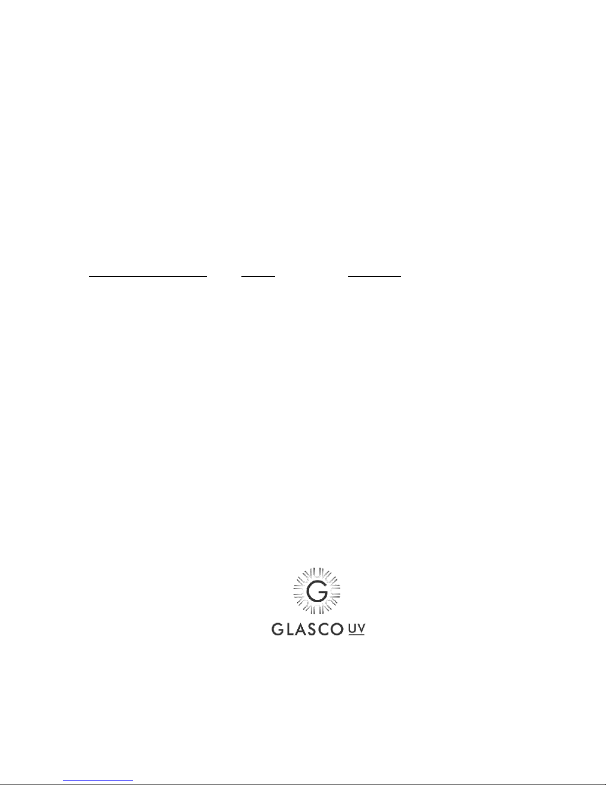
The solenoid valve will have an arrow on it indicating flow direction. Please install it the solenoid so that the path of the water
goes with the arrow.
Manual Quartz Cleaning System
Your system may have come with an optional manual quartz cleaning system. This device will allow you to
clean the quartz sleeve without having to disassemble the disinfection chamber.
! WARNING ! The plunger may be forced out when water pressure builds up. When installing the unit, make
sure that you stand clear of the plunger when pressurizing the system.
In order for the system to work at optimum performance, you must clean the quartz on a periodic basis. To
clean quartz, pull the plunger toward you and then push it in again. Do this a few times a month.
You may need to change the o-rings on the wiper on a periodic basis. Please open the system once a year to
inspect the quartz and the wiper rings.

August 2009
5 MICRON PRE FILTER
WATER STORAGE
PRESSURE TANK OR
(CITY WATERSUPPLY)
HOT WATER
TANK
HOT WATER SUPPLY
COLD WATER SUPPLY
BALL VALVE
UNION
BALL VALVE
UNION
GFCI PROTECTED CIRCUIT
ULTRAVIOLET PURIFIER
UL:TRAVIOLET POWER SUPPLY
ALLOW SPACE TO
REPLACE LAMP & QUARTZ
UNIT CAN BE MOUNTED HORIZONTALLY, VERTICALLY,
UP SIDE DOWN, INLET AND OUTLET ARE INTERCHANGABLE

August 2009
WARRANTY REGISTRATION
MODEL NUMBER/TYPE: ________________________
DEALER NAME: ___________________________
PURCHASE DATE:_________________________
NAME:______________________________________________________________
ADDRESS:___________________________________________________________
CITY: STATE: ______POSTAL CODE: ___
COUNTRY:_______________
PHONE:_______________ EMAIL:__________________________
Please fill out the above information and forward it to your dealer or to Glasco UV LLC. This will provide you with a
7-year warranty on the stainless steel chamber and a 1-year warranty on the electrical components. UV lamps are
warranted for 30 days. After the initial 30 days of operation, replacement or refund will be pro-rated based on the
expected lamp life of 9,000 hours.
In addition, this will allow your dealer to remind you when it is time to replace your lamp and quartz.
This warranty applies to equipment that has been installed and maintained according to the instructions in this
manual. Glasco UV LLC is not responsible for damage due to improper use, operation or installation.
This warranty needs to be received by Glasco UV LLC within 25 days of initial operation. The warranty applies to
replacing defective equipment.
Glasco shall have no liability hereunder, either direct or contingent, for any consequential damages. Glasco
recommends that you use pre-filters, flow-control devices and inspect the lamp to insure that it is functioning.
31 Industrial Avenue, Ste #3
Mahwah, NJ 07430
(201) 934-3348 Fax (201) 934.3388
This manual suits for next models
3
Table of contents
Other Glasco UV Water Filtration System manuals
Popular Water Filtration System manuals by other brands

SKF
SKF Lincoln 84013 Installation instruction

Oase
Oase BioSmart 1600 operating instructions

UV Dynamics
UV Dynamics UVD400 Installation and maintenance manual

Excalibur Water Systems
Excalibur Water Systems FILTERMAX ZENTEC Installation and user guide

HST
HST WFS-1545 Original instructions

AREBOS
AREBOS AR-HE-SA/G/S Original user manual

Zip
Zip HydroTap G5 Touch-Free Wave Quick start installation guide

wpro
wpro APP100 Procedure for installation and replacement

Zip Heater
Zip Heater HydroTap G4 user guide

IST
IST MRO001 instruction manual

ELECTOR
ELECTOR REFILL plus Series operating manual

PureEffect
PureEffect Compact installation instructions