Fitting Instructions
Post and ‘Ground- Lock’ Fixing System.
IMPORTANT NOTE: ENSURE THAT ALL RELEVANT PERSONNEL READ THE POINTS LISTED BELOW AND THAT A
COPY IS GIVEN TO THE STAFF INVOLVED WITH THE INSTALLATION
RETRIEVER 50™
When selecting a site, ensure there are no buried services.
Parts list
1 ) Bin and Key x1
2 ) Post for Ground-Lock version x1
3 ) M6 x 12mm Stainless Steel Security screw x2
4 ) M10 x 30 slotted panhead screw x2
5 ) M10 Lock washer x2
6 ) Security Allen key x1
7 ) Ground-Lock socket x1
8 ) M10 x 70mm Bolt x1
9 ) M10 metal Washer x1
10) Socket Block x1
11) * Installation cap x1
12) * Insertion tool x1
*Supplied separately by Glasdon
Glasdon U.K. Limited
Preston New Road
BLACKPOOL
Lancashire FY4 4UL
Tel: 01253 600410
Fax: 01253 792558
e-mail:sales@glasdon-uk.co.uk
web:www.glasdon.com
4747/GM/11.03
AND RETRIEVER 50 ARE TRADEMARKS OF GLASDON GROUP
OR ITS SUBSIDIARIES IN THE U.K. AND OTHER COUNTRIES.
Equipment Needed for Installation (not included)
17mm Socket spanner
Socket Wrench
15mm Spanner
Flat Headed Screwdriver
Safety Shoes
Sledge Hammer
Suitable Gloves
Ear-Defenders
Spade or Trowel
Diagram 6
N
L
L
C
M
E
D
A
B
Stage one
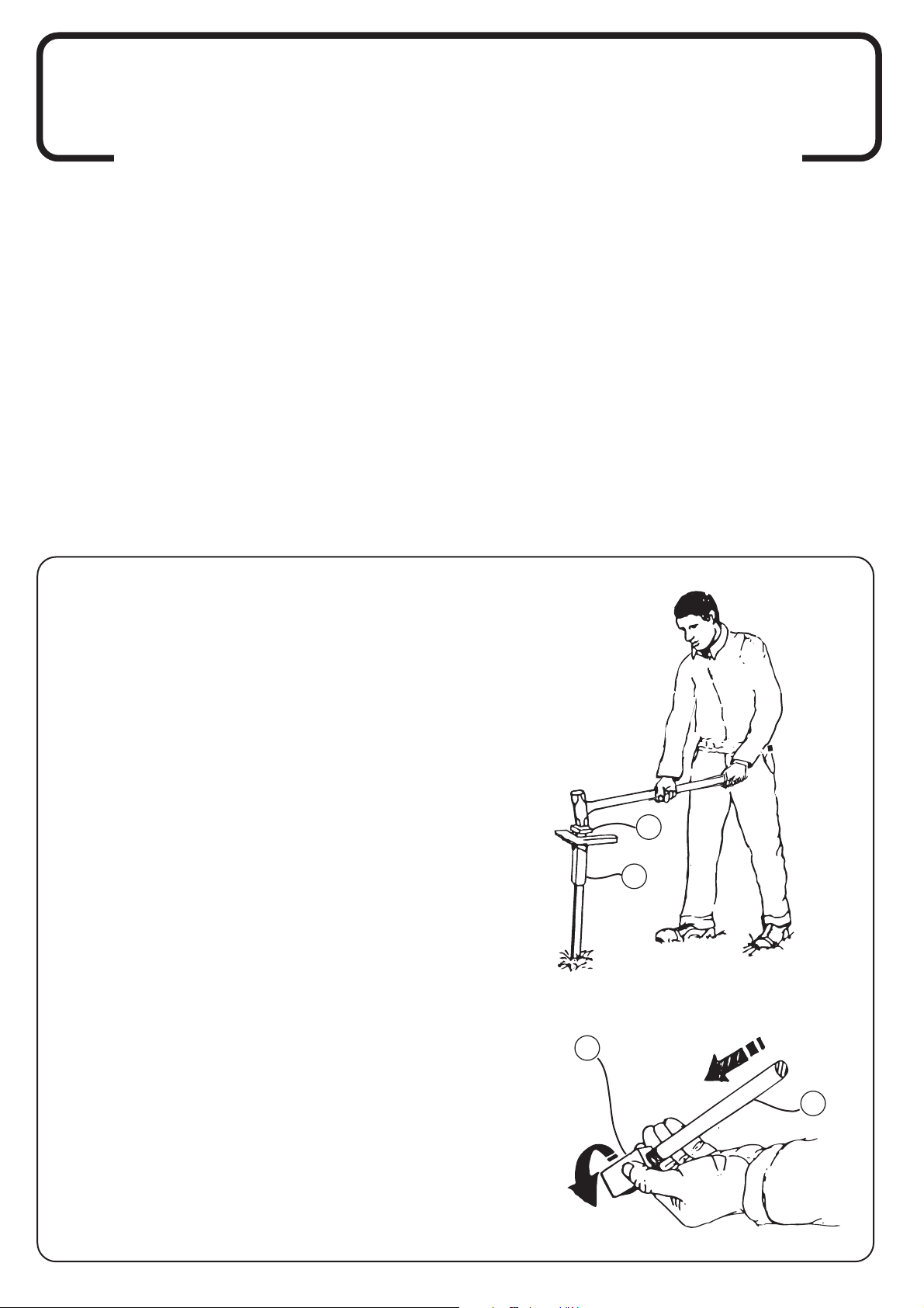
Remove the safety tube from the end of the ‘Ground-Lock’
leaving the BURIED SERVICES STICKER in place.
Push the Ground-Lock ( 7 ) socket spike into the chosen
ground in a vertical position until it stands alone, ensuring
that when bin and post are finally fitted the correct
orientation is achieved.
Position the installation cap ( 11 ) See Diagram 1.
Note:- If the ground conditions are hard, a two man
operation may be required to achieve a satisfactory
installation.
Hammer the ‘Ground-Lock’ into the ground with even
strokes until the horizontal bracket (affixed to the top of the
‘Ground-Lock’) is level with the ground.
When half way into the ground check the vertical position
and adjust if necessary then continue installation until the
top of the ‘Ground-Lock’ is at ground level.
Remove and retain the installation cap ( 11 ) for further use.
Stage two
Take the socket block ( 10 ) and screw onto the end of the
insertion tool ( 12 )
Ensure that the socket block is screwed hand tight only to
the threaded end section. See Diagram 2.
Then using the tool insert the block into the socket. See Diagram 3.
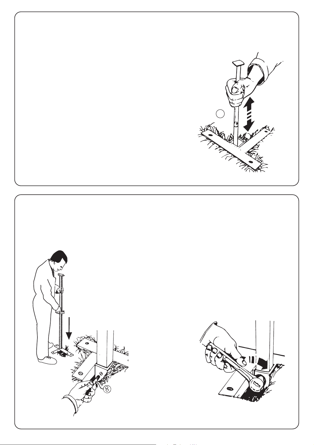
Stage three
Ram the insertion tool downwards to activate the barb securing
the ‘Ground-Lock’ into position.
When the arrow on the insertion tool is showing level with the top
of the socket, the ‘Ground-Lock’ is fully engaged. See Diagram 3.
Twist the insertion tool anti-clockwise to separate from the socket
block, then remove insertion tool and retain for further use.
Diagram 1
Diagram
3
Diagram
2
Diagram
4
Diagram
5
Stage four
Having installed the ‘Ground-Lock’ remove earth locally
from around the top to expose the fixing bolt hole for the
post. See diagram 4.
Line the fixing holes up on the post and socket and then
insert the post into the socket to achieve the preferred bin
orientation.
Insert bolt ( 8 ) and tighten until the post is held firmly in
the socket. See Diagram 5.
Replace earth around the base to disguise the fixing point.
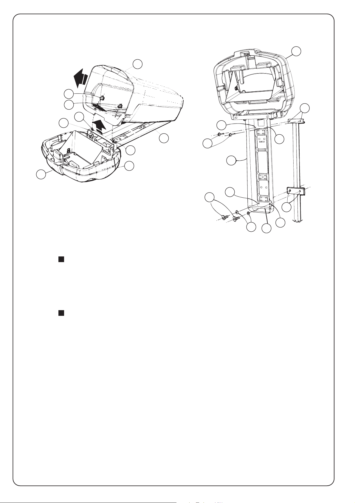
Stage five.
METHOD :- Assembly to Post.
To mount the bin onto the post it is first necessary to separate the bin base away
from the hood and stainless steel backbone components. See Diagram 6
Separate the base ( D ) by unlocking the bin at point ( M ) in a horizontal position
with the key provided. Release and remove both top fixings ( A & B ) with a 15mm
spanner from inside the base, these hold the base to the retainer bar. ( C )
Pivot and lift the base ( D ) away from the metal backbone ( E ) and place base
safely to one side.
With assistance to support the hood component ( N) align the metal backbone ( E )
up with the post threaded fixing points ( P ) and secure with fixings ( 3,4 & 5 )
through holes ( F,G, H & J ) See Diagram 7. Note The security Allen Key provided
with the kit is required at this point to fix M6 x 12mm Security Screws.
2
1
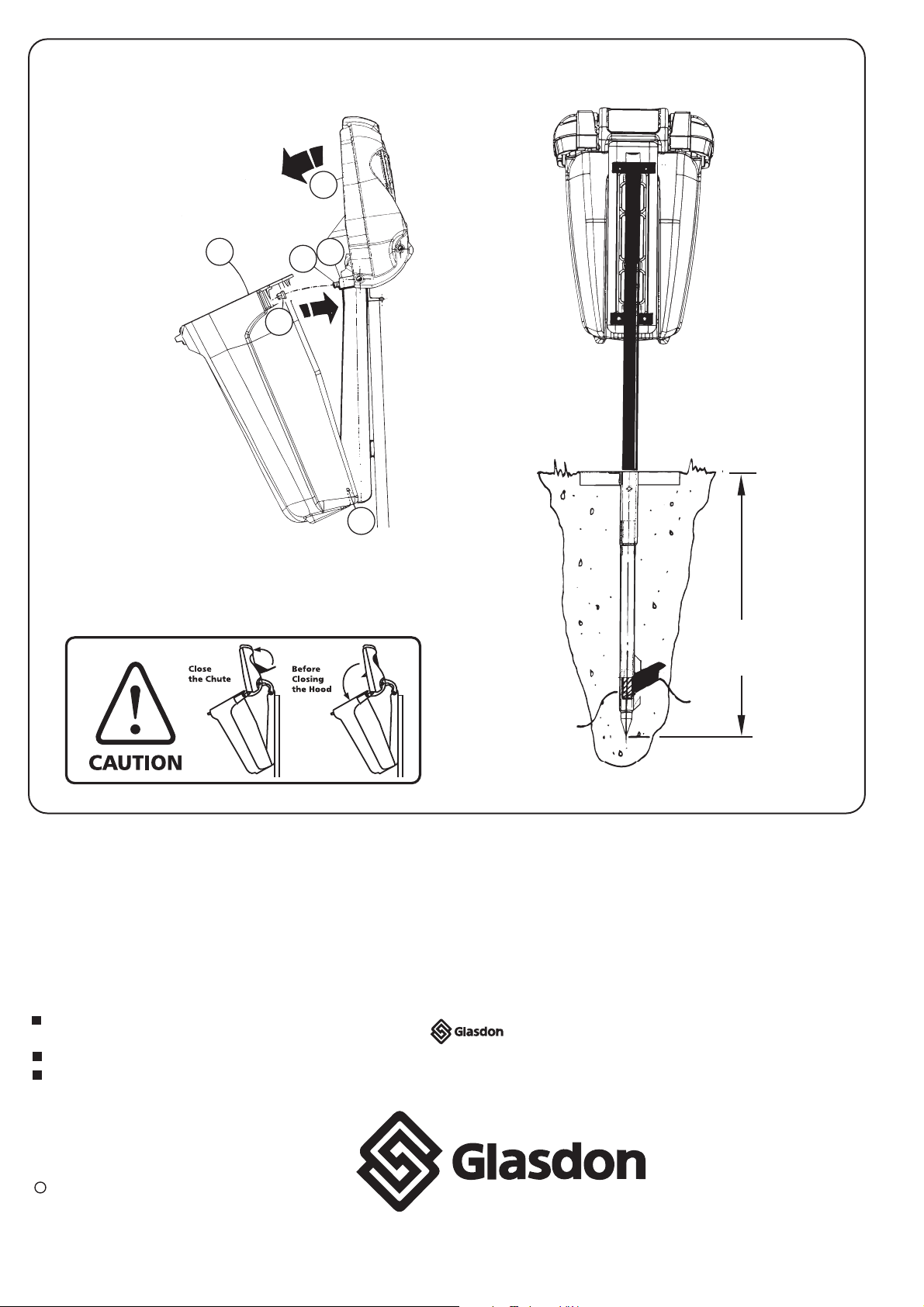
DEPTH
BELOW GROUND
(860MM)
Barb
Activated
Socket
Block
Diagram 7
K
F
E
N
4
5J
P
G
P
Diagram 8
D
N
LC
K
A-B
12
11
7
10
12
H
Replace the base ( D ) by lifting the hood ( N ) clear and connecting the lower point feature in the base with the
pivot rod ( K ) within the metal backbone. Align both upper fixing hole points in the base with the retainer bar
threads ( L ) in the hood and replace and secure fixings ( A & B ) . See Diagram 8.
3
The bin interior can now be prepared operationally for use depending upon liner choice.
The hood will lock without the use of a key by lowering it onto the base and slamming shut.
3
Issue 2 March 2004 Stock no. C000/0258
Copyright March 2004
Glasdon reserve the right to alter specification without prior notice.
A planned maintenance schedule of regular inspection is
recommended, replacing components as necessary.
Replacement components are available direct from GLASDON UK LTD.
GLASDON UK LTD. cannot be held responsible for claims
arising from incorrect installation, unauthorised
modifications or misuse of the product.
C
CAUTION - METAL CHUTE VERSION
During emptying or maintenance procedures
ensure that the caution notice is observed
when closing the hood section assembly.