manuals.online logo
Brands
  1. Home
  2. •
  3. Brands
  4. •
  5. Glasdon
  6. •
  7. Projection Screen
  8. •
  9. Glasdon VISAGE 770 SCREEN SYSTEM User manual

Glasdon VISAGE 770 SCREEN SYSTEM User manual

P. 1
KIT CONTENTS: 770L 1280L
ITEM A Side Panel x1 x1
ITEM B Front Panel x1 x1
ITEM C Side Panel x1 x1
ITEM D 5mm x 20mm Chipboard Screw x29 x33
ITEM E M10 x 120mm Ground Fixing Bolt x6 x6
ITEM F Support Leg x2 x2
ITEM G Side Skirting (optional) x2 x2
ITEM H Front Skirting (optional) x1 x1
ITEM I Repair Washer M5 x 25mm S/S x16 x20
(optional)
Assembled
Three Sided
Screen
(770 L)
AND MODUS ARE TRADEMARKS OF GLASDON GROUP AND ITS SUBSIDIARIES IN
THE U.K. AND OTHER COUNTRIES.
Replacement components are available direct from GLASDON.
GLASDON cannot be held responsible for claims arising from incorrect installation, unauthorised modifications or misuse of
the product.
Issue 2 December 2011 C000/0406
© Copyright 2011
Glasdon U.K. Ltd reserves the right to alter specifications without prior notice. Preston New Road
BLACKPOOL
Lancashire FY4 4UL
Tel: 01253 600410
Fax: 01253 792558
E-mail: [email protected]
Web: www.glasdon.com
TM
FRONT SIDE
VISAGE SCREEN SYSTEM - THREE SIDED (FLAT PACK)
ASSEMBLY & FIXING INSTRUCTION LEAFLET
TM
A B C D E
FGHI
TOOLS REQUIRED:
13mm Spanner x1
Hand Drill with Pozi Drill Bit x1
10mm x 150mm Masonry Drill Bit x1
Rubber Mallet x1
Hammer x1
17mm Spanner x2
6mm Allen Key x1
NOTE: Ensure that all relevant personnel read the points listed below and that a copy is passed on to staff involved
with the installation. Please also refer to the ‘Manual Handling Operations Regulations 1992’ during the
handling of the product and materials used for installation. The total weight of this product is 53kg (770L) and
65kg (1280L).
NOTE: Some xings apply to the optional skirting
so there may be less xings than stated.
We recommend that a risk assessment is undertaken to identify an appropriate location for your waste
collection and recycling units. In order to reduce risk, some organisations decide to place the units a minimum
of 5 metres away from buildings. Any potential risk can be further reduced by maintaining a regime of regularly
emptying the unit.
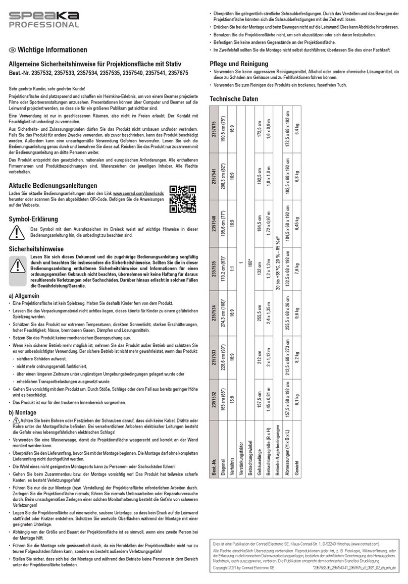
Step 1: Assembly of Three Sided Screen
1
4 5 6
P. 2
Hold panel (B) up to the left hand
extrusion on panel (A) ensuring
that the feet with the pre-drilled
holes are on the ground. Push the
end of the board into the
extrusion slot.
Using rubber mallet (so not to
damage the extrusions) tap the
side at the top of the extrusion so
that the board is pushed rmly
into the extrusion without any
gaps.
Tap the top of the extrusion to
ensure the board is level up to the
top of the extrusion cover cap.
Using hand drill and screw
provided (D), secure the top xing
in position by screwing from the
inside of the extrusion into the
board.
Using rubber mallet, tap the side
at the bottom of the extrusion to
ensure that the board is pushed
rmly into the extrusion without
any gaps.
Using hand drill and 6 o screws
provided (D), secure the
remaining xings on the inside of
the extrusion by screwing through
the extrusion into the board.
2 3
7
With two panels assembled oer
panel (C) up to the left hand
extrusion on panel (B) ensuring
that the feet with the pre-drilled
holes are on the ground. Push the
end of the board into the
extrusion slot.
Using rubber mallet, tap the side
at the top of the extrusion so that
the board is pushed rmly into
the extrusion without any gaps.
Tap the top of the extrusion to
ensure the board is level up to the
top of the extrusion cover cap.
8 9
13
Using a 13mm spanner/socket
unscrew the two bolts with
washers on the inside at the
bottom of the extrusions and
remove.
Lift the extrusion upwards and
pull the spigot leg down to a
more appropriate height ensuring
that the screen is now level.
Replace the bolts and washers into
the new holes within the spigot leg
and tighten with spanner/socket.
Repeat Figs 13-15 on the other legs
that need adjusting.
14 15
Step 2: Adjustment of Spigot Legs When Sited on Uneven Ground
(If not required move on to Step 3)
Step 3: Ground Fixing (Concrete In)
16 17 18
Using a 10mm masonry drill bit,
drill through the hole in the spigot
leg down into the concrete
approximately 150mm deep.
Tighten bolt using 17mm
spanner. Repeat Figs 16-18
to ground x the other
three extrusions.
10 11 12
Using hand drill and screw
provided (D), secure the top xing
in position by screwing from the
inside of the extrusion into the
board.
Using rubber mallet, tap the side
at the bottom of the extrusion to
ensure that the board is pushed
rmly into the extrusion without
any gaps.
Using hand drill and 6 o screws
provided (D), secure the
remaining xings on the inside of
the extrusion by screwing through
the extrusion into the board.
P. 3
The xing bolts (E) MUST appear as
above with the nut and washer at the
top of the bolt. Using a hammer, tap
xing bolt through the hole in the spigot
leg until it is ush with the spigot plate.
P. 4
23 24 25
Step 5: Attaching Rubber Skirting (Optional)
Using side skirting (G), on the
INSIDE of the screen, align the end
of rubber next to the extrusion so
that it is touching the ground.
Using a screw (D) and washer (I),
screw the xing through the
pre-drilled hole in the skirting into
the board.
Repeat Fig 24 using the other xings
along the skirting ensuring to pull
the rubber tight inbetween each
point. Repeat Figs 23 - 25 using
second side skirting (G) and front
skirting (H).
Using a 13mm spanner/socket unscrew the two bolts with
washers at the bottom of the outermost extrusions and
remove. (see diagram above showing location of support
legs) If the spigot legs have been adjusted (Step 2) the panels
will need to remain lifted in position so that the support legs
go into the correct holes (may require two people).
Place the support leg (F) up against the
inside of the extrusion so that the leg
protrudes outwards and stands on the
ground. If the spigot legs have been
adjusted there are several pre-drilled
holes in the support leg to accommodate
this adjustment.
Replace the bolts and washers into
the new holes through the support
leg, extrusion and into the spigot leg.
Tighten with 13mm spanner/socket.
Ground x the support legs into
the ground as per Figs 16 - 18
(Step 3).
Step 4: Attaching and Ground Fixing Compulsory Support Legs
19 20
21 22
Three Sided

This manual suits for next models

1

Popular Projection Screen manuals by other brands

JT Motors CINEFRAME 75 Mounting instruction

JT Motors

JT Motors CINEFRAME 75 Mounting instruction

Grandview GRUC040V user manual

Grandview

Grandview GRUC040V user manual

Dukane ImagePro 8778 Specifications

Dukane

Dukane ImagePro 8778 Specifications

Vivid VFS392FS user manual

Vivid

Vivid VFS392FS user manual

JUMO LOGOSCREEN operating manual

JUMO

JUMO LOGOSCREEN operating manual

LEGRAND DA-LITE Tensioned Advantage Series user manual

LEGRAND

LEGRAND DA-LITE Tensioned Advantage Series user manual

NoFlyStore Silver.04 installation instructions

NoFlyStore

NoFlyStore Silver.04 installation instructions

Phantom Executive 4" Recessed Installation Manual

Phantom

Phantom Executive 4" Recessed Installation Manual

Genius Sierra 800 installation instructions

Genius

Genius Sierra 800 installation instructions

Denver PFF-1011 user manual

Denver

Denver PFF-1011 user manual

STILFORD JBSC124WBK Assembly instructions

STILFORD

STILFORD JBSC124WBK Assembly instructions

TEREN THD quick start guide

TEREN

TEREN THD quick start guide

HEAT GLO FS-3-BK installation instructions

HEAT GLO

HEAT GLO FS-3-BK installation instructions

Cima Above Ceiling ElectriScreen owner's manual

Cima

Cima Above Ceiling ElectriScreen owner's manual

STILFORD JBSCR751BK Assembly instructions

STILFORD

STILFORD JBSCR751BK Assembly instructions

Grandview Edge R7 Guide

Grandview

Grandview Edge R7 Guide

Weizhen WZ-VC-4 Operation manuals

Weizhen

Weizhen WZ-VC-4 Operation manuals

DMT Fast-Setup Screen Pro manual

DMT

DMT Fast-Setup Screen Pro manual

manuals.online logo
manuals.online logoBrands
  • About & Mission
  • Contact us
  • Privacy Policy
  • Terms and Conditions

Copyright 2025 Manuals.Online. All Rights Reserved.