manuals.online logo
Brands
  1. Home
  2. •
  3. Brands
  4. •
  5. GlassCrafters
  6. •
  7. Shower Cabin
  8. •
  9. GlassCrafters EPIC Series User manual

GlassCrafters EPIC Series User manual

Frameless Corner Enclosure Buttress Enclosure
888-683-1362
6/1/15
IF YOU NEED REPLACEMENT PARTS OR HAVE INSTALLATION QUESTIONS,
PLEASE CALL OUR CUSTOMER SERVICE REPRESENTATIVES.
INSTALLATIONS SHALL BE MADE ACCORDING TO MANUFACTURER’S INSTRUCTIONS AND DRAWINGS.
GLASSCRAFTERS RECOMMENDS THE INSTALLATION TO BE PERFORMED BY A TRAINED INSTALLER.
Model By-Pass Sliding Doors Installation Instructions
Tub or Shower By-Pass Sliding Doors with Return Panel
Models ET9 - ES9, with Buttress Return Panel Models ETB9 - ESB9
[email protected]
Item No. Description Qty.
#1
#2
#3
#4
#5
#6
#7
#8
#9
#10
Header
Base
Wall Jamb
Glass Door
Glass Door
Base Vinyl
Jamb Bumper
#6 x 1/2”Screw
Roller
Glass Hanger
1 (2 pcs)
1
2
1
1
1
2
2
4
2
#11
#12
#13
#14
Wall Anchor
#8 x 1 1/4”Screw
Towel Bar Pack
Center Guide
Header Filler
6
8
1 Set
1
1
#16
#15
Safety Stop 3
#17 10-32 x1/2 Screw 4
#18 Setting Block
#19
#20
#21
#22
Wall Channel
90 Deg Return Post
Return Glass Panel
Base Channel
1
1
1
1
Item No. Description Qty.
#1
#2
#3
#4
#5
#6
#7
#8
#9
#10
Header
Base
Wall Jamb
Glass Door
Glass Door
Base Vinyl
Jamb Bumper
#6 x 1/2”Screw
Roller
Glass Hanger
1
1
2
1
1
1
2
2
8
2
#11
#12
#13
#14
Wall Anchor
#8 x 1 1/4”Screw
Towel Bar Pack
Center Guide
Header Filler
6
8
1 Set
1
1
#16
#15
Safety Stop 3
#17 10-32 x1/2 Screw 4
#18 Setting Block
#19
#20
#21
#22
Wall Channel
90 Deg Return Post
Return Glass Panel
Base Channel
1
1
1
1
For 1/4” GLASS FOR 3/8” GLASS
CAUTION: Risk of injury or product damage. Do not attempt to cut tempered glass.
IMPORTANT! Children should be supervised at all times while in Tub/Shower Enclosure.
IMPORTANT! Never use Door Handle to support yourself. This is for towels or wash cloths only.
PLEASE STOP THE INSTALLATION AND CONFIRM WITH FACTORY IF
THE ACTUAL NUMBER OR TYPE OF PARTS IS DIFFERENT.
When ordering replacement parts,please specify the Model Number,Item Number & PartDescription.
Save these Installation Instructions For The Future Reference.
Write your Dealer information down on Notes Section.
Ask your Dealer for JOB LOG NUMBER (Lxxxxxx-xxx) Referencing to your shower enclosure.
A - Safety glasses.
B - Measuring tape.
C - Pencil.
D - Hack saw or chop saw
(with carbide teeth).
E - Miter Box or Square.
F - Level.
G - Electric Drill.
H- Center Punch
I - Drill bit, 1/8”
(for installation on a fiberglass
enclosures)
Drill bit, 3/16” masonry
(for installation on ceramic tiles or marble)
J - Power screwdriver
K - #2 phillips screwdriver
L - Caulking gun
Tools Required - For installation of Your Shower Enclosure
#1- Flat Header
(optional)
#2- Base #3- Wall Jamb
#14- Center Guide
#7-Jamb Bumper
#6- Base Vinyl
3/8” Glass
#6- Base Vinyl
1/4” Glass
#12 -1 1/4”Screw
#8- 6x1/2”Screw
#11- Wall Anchor #16- Safety Stop
#15- Header Insert
#9- Roller
#17- 10-32 x 1/2”
Machine Screw
#1- Round Header
#24- Wall and Base
Filler (if applicable)
#25- Set Of
Towel Bars #26 -1 1/4”Screw
#18 -Seting Block #19 -Wall Channel
#22 -Base Channel
#23 -Glazing Vinyl
comes with 1/4”
Inline panel
#20 -Return Post
#27- 6x3/8”Screw #28- Header Bracket
#29- 90 Degree
Header Bracket
22
Pa
g
e 2 of 15 4/2/2010
22
11
15
28
12
21
18
10
7
6
8
14
4
16
17
5
13
2
9
3
26
1
20
Installation shows 3/8” glass by-pass shower enclosure with two standard towel bars. Other units may vary.
Installation shows Round Header. Flat header is Optional.
ROUND HEADES SECTION
FLAT HEADES SECTION
View form Inside of Tub/Shower
29
Pa
g
e 3 of 15 4/2/2010
1
2
Sketch 1 A
Sketch 2 A
“A”
Installation Instructions for GlassCrafters Epic By-Pass Shower Enclosure
IMPORTANT: Read all instructions carefully and become familiar with all parts before installation.
Cleaning: Never use scouring powder, pads or sharp instruments on metal work or glass panels.We recommend
the use of a squeegee after each shower to eliminate water spots on the inside of the glass panels.
An occasional wiping down of the glass panels and anodized aluminum parts with a mild detergent,diluted in water,is
all that is needed to keep your Shower /Tub Enclosure looking brand new.
Unpacking: Care should be taken unpacking your Shower Enclosure.Place the Glass Panels in an upright,
Safe location to avoid damage.Never place glass directly on hard surface.
A Box cutter should not be used to open box.
Please remove all staples from the box prior to unpacking metal and glass.
IMPORTANT:
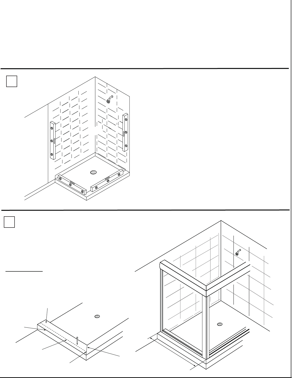
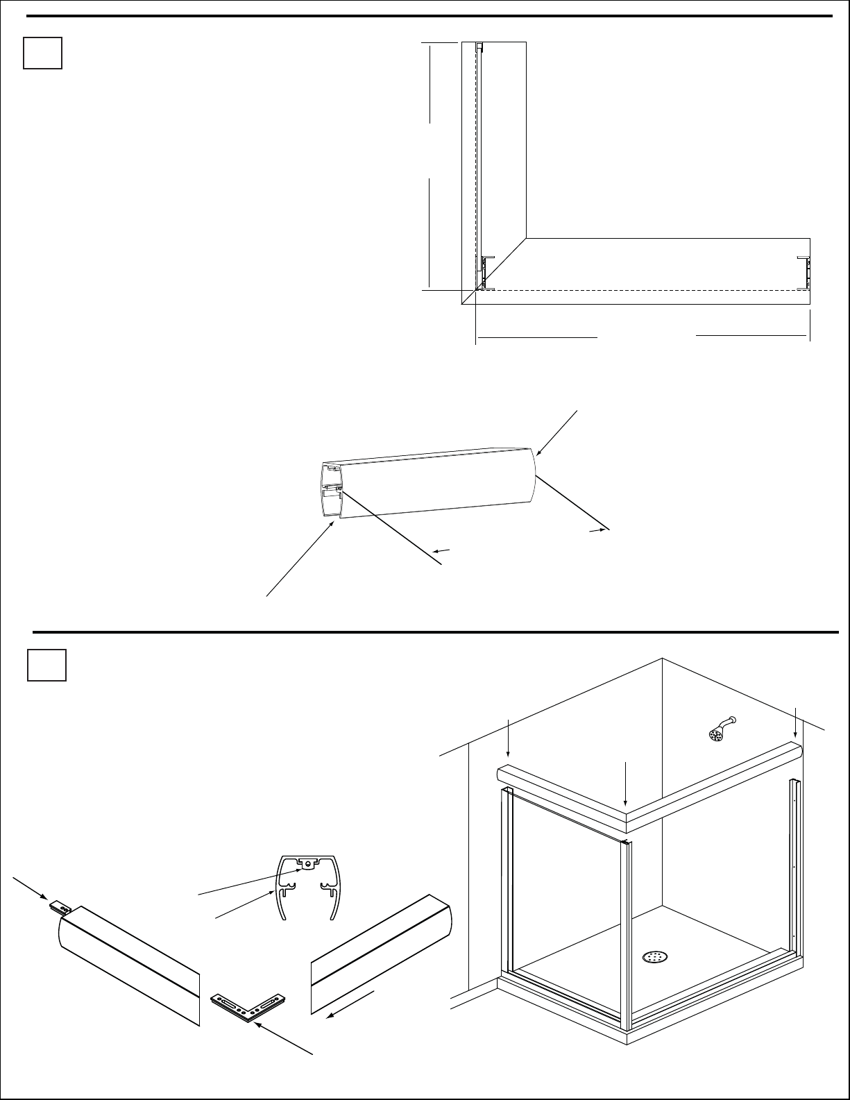
Determine if your Tub/Shower Stall Enclosure ledge is
Level and Wall are plumb as shown in Sketch 1A.
If they are out of Level/Plumb, by more than 1/4”, STOP!
and call Customer Service. The Phone number is
1-888-683-1362
A Base filler and /or Wall Jamb Filler are recommended
for obtaining proper adjustment;
both are available through Customer Service.
If they are Level/Plumb, or out of Level/Plumb for less than
1/4” proseed with installation.
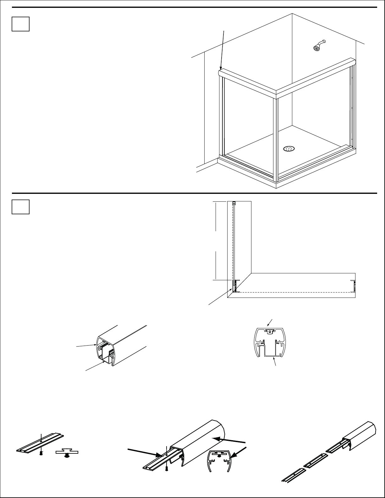
The Base Channel # 22 for return panel is cut per size on factory.
Locate that channel among supplied parts and measure It .
Add 2 5/8”to the measurement. That is the size from return wall
to the front of unit. See Sketch 2A for detail.
“A” = BASE CHANNEL #22 + 2 5/8
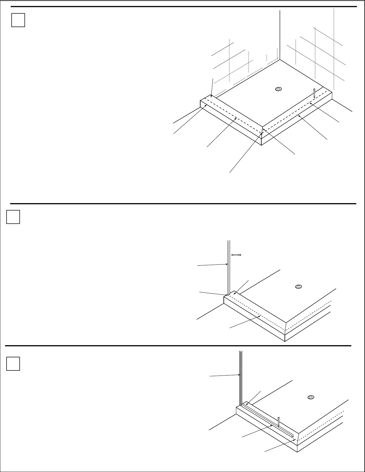
Using pencil and ruler draw a line (OD Line) on the curb
equal to size ”A”. Make sure that Open-end
of the line (opposite to wall end) ends at
curb-break line. Also make sure that it
is parallel to curb’s front edge. See Sketch 2A for detail.
Curb
OD Line
Curb’s Front
Edge
Curb-Break
Line
Open-end of Line
ends at Curb-Break Line Pa
g
e 4 of 15 4/2/2010
3
4
5
Set the wall Channel #19 on return wall. The front face of the channel should match with OD line.
Use level to make sure that it is plumb. Using pencil mark the hole locations on the tile.
Remove the Wall Channel#19 and drill the holes. Insert Wall Anchors#11
See Sketch #4A.
Curb
Wall
Channel#19
Front face of Channel
matches with OD line
OD Line
Clean curb and extrusion from dust and tile debris.
Set Wall Channel#19 and fasten it to the wall with Screws #12
Curb
Wall
Channel#19
OD Line
Base Channel #22
Set the Base Channel #22 on return curb.
The front face of the channel should match with OD line.
Use pencil to mark holes locations on the curb. Remove the
Base channel. Drill the holes. Insert Anchors# 11. Clean the curb
from dust and debris. Set Base Channel # 22 back and fasten
it to curb with Screws# 12 . See Sketch #4A.
Sketch #5A.
Sketch #4A.
Sketch #3A
Using pencil and ruler draw a line connecting open end of
return OD-line and wall. That is a Front OD-line.
Make sure it is parallel to curb’s front edge.
Use an angle-finder or square to make sure that
Return and Front OD-lines are making 90 degree angle.
If the angle is not 90 degree, then it is necessary
to measure the difference.
If the resulting angle differs from 90 by just
1-3 degrees then continue with installation.
If angle difference is more, contact factory for further instruction.
See Sketch #3A.
Curb
Return OD Line
Curb’s Front
Edge
Curb-Break
Line
Open-end of Line
ends at Curb-Break Line
Front OD-Line
Curb’s Front Edge
Pa
g
e 5 of 15 4/2/2010
6
7
Wall
Jamb#3
Front face of Channel
matches with OD line
Sketch #6A
Sketch #6B
1/16
Shim
Wall Jamb
Base
Jamb Bumper
Screw #26
Wall
Jamb#3
Sketch #7A
“B”
Wall Jamb # 3 is cut per size on factory.
Place a 1/16shim on the corner by opposite wall, where Wall Jamb#3 will be installed
Position Wall Jamb #3 on top of 1/16shim (Sketch #6A). The front face of the channel should match with OD line.
Mark locations of holes. Remove Wall Jamb #3 and drill the marked holes.
Clean curb and extrusion from dust and tile debris.
Secure Wall Jamb #3 with Screws #12 using top and bottom hole.
For middle anchor use Screw #26and Jamb Bumper # 7 .See Sketch #6B for detail.
Screw #12
Base #2 is left oversized on factory.
Using a tape-measure measure the length“B” of
the Front OD-line as it is shown on Sketch#7A.
Subtract 1” from size “B”. That is the size of Base#2.
Cut Base#2 to the size.
To obtain the best results, use a carbide tooth
metal cutting chop saw or metal hack saw.
Pa
g
e 6 of 15 4/2/2010
8
9
Sketch #8B
Sketch #8A
Sketch #8C
Sketch #9A
Sketch #9A
Sketch #9C
IN
UNDER
Inside
of shower
Look from Inside
of shower
Outside
of shower
Silicone Sealant
Base # 2
Wall Jamb
Base
Jamb Bumper
Remove 1/16”shim from under the Wall Jamb #3.
Apply a thick continuous bead of Silicone Sealant
to the underside of the Base, as shown in Sketch #8A.
Set the Base #2 on the curb fitting it UNDER and IN
wall jamb #3, as it shown on Sketch #8B
It gap under wall jamb#3 is not big enough
for Base #2 to slide, loose the fastening Screws #12
and #26 on Wall Jamb#3 and shift it up.
When Base #2 is set, use a clean paper towel
to wipe off the exes silicon from curb.
Set Blocks # 18
Carefully Set the Glass Panel into Wall Channel #19 and Base Channel #22. See Sketch # 9A
Be careful not to chip or strike the glass edges. Glass can break if edges are not handled properly.
Place Wall Channel #19 and Post Return # 20 into position as shown in Sketch #9C.
Use a level to make sure that Corner Post (combined Wall Jamb#3 and Return Post #20) is plumb
in both directions. Use few strips of masking tape to immobilize Corner Post in that position.
Pa
g
e 7 of 15 4/2/2010
10
11
Sketch #10A
Mitered Edge. Sketch #10B
Sketch #11A
Sketch #11B
TOP VIEW
C
D
The Headers#1 are left oversized on the factory
and must be cut to size based on“C” and “D”
For Round Header
Header for Return =“D” + 7/16”
Header for Front = “C” + 7/16
For Flat Header
Header for Return =“D” + 1/8”
Header for Front = “C” + 1/8”
The Cutting must be performed at Flat end of header.
Measurements must be performed from“long point” to “point”.
See Sketch #10B for details.
To obtain the best results, use a carbide tooth
metal cutting chop saw or metal hack saw.
L
o
ng
Po
i
n
t
to Poin
t
Flat edge.
Cut at here.
In
In
In
Header
Bracket
Insert the Header Bracket #28 and
90 Degree Header Bracket #29 into
the return Header as it shown on Sketch #11A.
Using Allen French Slightly tighten the Allen screws to
fix brackets inside the header. Attach the front header.
Set the Headers on top of wall jamb#3 and Corner Post.
Use level to make sure that the Header is level.
Pa
g
e 8 of 15 4/2/2010
12
13
Sketch #12A
Mark Header Bracket
hole locations here.
Standing inside of the shower Mark the Hole location
of the Header Bracket # 28 on tile. Sketch #12A.
With Header still on Measure Size“E”. See Sketch #13A.
The size“E” will be used in next step.
Lift up and remove the Header Assembly from
Wall Jamb#3 and Corner Post.
Remove Corner Post as well as Return Glass Panel.
Be careful when handling Glass. It will shatter if mishandled.
Drill Hole For Header Bracket and Insert Anchor #11.
Clean the Dust and Debris.
Outside of
shower
Outside of
shower Inside of
shower
Inside of
shower
Set the Header assembly back and fasten it to the wall
using Screw#12
Header Insert #15 is left oversized on factory.
Previously measured size“E” is a cut size for it.
Cut Header Insert#15 to size.
Snap the Header Insert #15 Into Return Header
Flush with back side of it.
See Sketch#13B and #13C for details.
Sketch #13A
Sketch #13C
Sketch #13B
TOP VIEW
E
Corner Post
Back end
of Return Header
Header Insert
Flush with Header
Return Header
Header Insert#15
Sketch #13D Sketch #13E
Sketch #13F
Header
Safety Stop
Open Safety Stop Package. Insert Screws into safety stops as shown in Sketch #13D. Insert Safety Stops
into Front Header as shown in Sketch #13E. Make sure to insert Safety Stop with 2 holes as shown in Sketch13F.
Pa
g
e 9 of 15 4/2/2010
Sketch #15A
Sketch #15B
Sketch #15C
14
15
Sketch #14A
Holding Return Panel Glass from sides and under a slight angle,
insert it up into the Header Insest#15, and then
down into Base Channel#1333 and Slide Left into
Wall Channel #3. Sketch #14A
Re-install Corner Post, fixing it
plumb on the glass with masking tape. If everything
is done right Corner post must just slide into open
gap between header and insert.
UP
Down
Slide
Header
Wall Jamb
Screw
View from Inside Shower Stall
Header
Wall Jamb
Screw
Inside Shower
Stall
Outside
Standing inside of the shower Drill and fasten Screw # 27 through the Header#1 into both Wall Jambs#3;
on wall side and Wall Jamb #3 in the corner of unit. (Sketch #15A, #15B and #15C)
Srews in
Wall Jambs
Pa
g
e 10 of 15 4/2/2010
16 Glass hangers are installed on to glass panels at factory.
Warning: The Glass Panels are heavy and awkward. It is recommended that two
people lift and hang the glass panels.
DO NOT LIFT GLASS PANELS BY THE TOWEL BARS/PANEL PULLS.
Outside
Step 1 Step 2 Step 3
Outside Outside
Slide Safety Stops to one side before attempting to install Glass Panels.
Panels fill not fit into Header with Safety Stops on the way.
Installing the Outer Glass Panel.
Standing inside of the Tub/Shower, Position the Glass Panel on front of Tub/Shower Enclosure
with the Rollers facing OUT Tub/Shower Enclosure.
Holding the Glass Panel by the sides, lift it up into the underside of the header, between roller ledges.
Working under a slight angle will make it little easier. (Step 1)
With the Glass Panel in vertical position move it toward the outer Track Ledge (Step 2)
making sure that rollers are above the ledge. Bring the glass down; let the rollers to get on
the ledge and inside the track(Step 3).
Slowly release, allowing the glass panel to hang freely from the header.
At this point if released, glass will not hang vertically, but under an angle.
While Holding the Glass vertically Slide the Glass Panel back-and-forth in the track.
Make sure that the rolling is smooth and easy.
Pa
g
e 11 of 15 4/2/2010
17
Step 1
Outside
Step 2
Outside
Step 2
Outside
Slide Safety Stops to one side before attempting to install Glass Panels.
Panels fill not fit into Header with Safety Stops on the way.
Installing the Inner Glass panel.
Standing inside of Tub/Shower, Position the Glass Panel on front of Tub/Shower Enclosure
with the Rollers facing IN Tub/Shower Enclosure. Holding the Glass Panel by the sides,
lift it up into the underside of the header, between roller ledges.
Working under a slight angle will make it little easier. (Step1)
With the Glass Panel in vertical position move it toward the inner Track Ledge
making sure that rollers are above the ledge. Bring the glass down(Step2), letting rollers to get on
the ledge and inside the track (Step 3). Slowly release, allowing the glass panel to hang from the header.
At this point, if released, glass will not hang vertically, but under an angle.
While Holding the Glass vertically Slide the Glass Panel back-and-forth in the track.
Make sure that the rolling is smooth and easy.
The Inner Glass Panel must be located on shower head side.
Glass hangers are installed on to glass panels at factory.
Warning: The Glass Panels are heavy and awkward. It is recommended that two
people lift and hang the glass panels.
DO NOT LIFT GLASS PANELS BY THE TOWEL BARS/PANEL PULLS.
Pa
g
e 12 of 15 4/2/2010
18
19
Outside
llatSrewohS/buT
Sketch 19A
View looking from inside
Tub/Shower Enclosure
Center Guide # 14
Screws # 8
Readjusting Rollers on the Glass Hanger.
NOTE: this step is only performed if necessary.
Remove Glass Panels from Header with same movement repeated backwards.
Please note there are a set of pre-drilled holes on hanger, Sketch 18B.
Using screwdriver, loosen and remove the screws that fasten rollers and hanger.
Move the rollers up or down to desired location. Fasten the screws back.
Make sure that screw is tight and roller
will not come off the hanger during the use. Sketch 18B
Sketch 18A
Installing Bottom Guide.
Stand inside the Tub/Shower Enclosure and slide both glass
panels to one side of the enclosure.
Install the center guide by sliding it to the center of the base.
Carefully drill 1/32”holes and insert screws as shown in SKETCH 19A
There should be 1/4-5/8 space between bottom edge of the glass and Base (Sketch 18A).
That space is necessary for Center Guide.
If it is less or more than mentioned limits the rollers must be moved up/down.
Outside
1/4”-5/8”
Pa
g
e 13 of 15 4/2/2010
20
21
Wall Jamb
#19
Glass Panel
Vertical Vinyl
TOP VIEW
180 Degree Post
#20
Slide into position
Sketch 12A
Sketch 12B
NOTE: A light spray of Glass Cleaner on the glass will help the
vinyl slide into position. Flat square block of wood can be
used to tap in vinyl.
3”x5”
Wooden block
Wooden Block
Insert Glazing Vinyl# 23 into Wall Channel #19,
Header Insert#15 , Base Channel #22, and
90 Degree Post #20. See Sketch#12A and 12B for details.
Use a wooden Block to tuck the vinyl in.
Slide into position
Wooden Block
Placing and securing Safety Stops
Slide Safety Stops into position and secure as shown in step 1-2
Some lines and Extrusions are not show for clarity
Step 2
Slide both Glass Panels to left.
Secure right Safety Stop and
Center Safety Stop as shown.
Slightly tight the screws on
the safety stops to wedge and
immobilize theam in Header.
Step 1
Slide both Glass Panels to right .
Secure right Safety Stop and
Center Safety Stop as shown.
Slightly tight the screws on
the safety stops to wedge and
immobilize theam in Header.
Glass Panel
Glass Panel
Safety Stop
Screw
Header
Screw
Header
Screw
Screw
Safety Stop
Sketch 21B
Header
Wall Jamb
Inside Shower
Stall
Outside
Pa
g
e 14 of 15 4/2/2010
Apply Silicone Sealant as shown
Be sure to add Silicone to both ends of the Base
where it meets the Wall Jambs, as shown in
SKETCH 22 A.
Please note that after applying Silicone
Sealant, it must not be used for 24 hours
to allow the sealant to set properly.
View looking from outside
Tub/Shower Enclosure
22
It is essential that Silicone Sealant be applied at
all locations indicated inside and outside,
as shown in SKETCH 22 B.
Silicone Sealant
Sketch #22A
Sketch #22B
Sketch #22C
If 3/8 Glass is user for Return Glass Panel
Apply a bead of Silicone Sealant to Glass Panel
Inside and Outside as shown in Sketch 22 C.
Pa
g
e 15 of 15 4/2/2010

Other manuals for EPIC Series

1

This manual suits for next models

4

Popular Shower Cabin manuals by other brands

Radaway Eos DWS Assembly instruction

Radaway

Radaway Eos DWS Assembly instruction

OVE SWIFT INSTALL 38 installation manual

OVE

OVE SWIFT INSTALL 38 installation manual

Insignia INS9005 installation manual

Insignia

Insignia INS9005 installation manual

Hornbach 1978-0 Assembly instructions

Hornbach

Hornbach 1978-0 Assembly instructions

Radaway Eos KDS Assembly instruction

Radaway

Radaway Eos KDS Assembly instruction

deante KTM 011P Assembly instructions

deante

deante KTM 011P Assembly instructions

Aquapeutics L52 Series installation manual

Aquapeutics

Aquapeutics L52 Series installation manual

KARAG FLORA 100 installation manual

KARAG

KARAG FLORA 100 installation manual

Wellis Sorrento plus 90 Instruction guide

Wellis

Wellis Sorrento plus 90 Instruction guide

deante KTS 030P Assembly instructions

deante

deante KTS 030P Assembly instructions

Artize QUADRO Manual for installation

Artize

Artize QUADRO Manual for installation

Kohler Pinstripe K-705707-L quick start guide

Kohler

Kohler Pinstripe K-705707-L quick start guide

Aurlane CAB270 Installation

Aurlane

Aurlane CAB270 Installation

Welltime Berlin 19763828 Installation instruction

Welltime

Welltime Berlin 19763828 Installation instruction

Kamalu KS8000 installation manual

Kamalu

Kamalu KS8000 installation manual

RIHO BALTIC B309 manual

RIHO

RIHO BALTIC B309 manual

Linie Tarifa installation guide

Linie

Linie Tarifa installation guide

OVE HARVARD 48 installation manual

OVE

OVE HARVARD 48 installation manual

manuals.online logo
manuals.online logoBrands
  • About & Mission
  • Contact us
  • Privacy Policy
  • Terms and Conditions

Copyright 2025 Manuals.Online. All Rights Reserved.