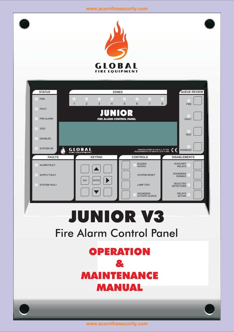
FAULTS
SUPPLY FAULT – This LED will be ON whenever the Main Supply has been removed or has dropped below 20 Volts.
BATTERY FAULT – Indicates that there is low voltage level on the batteries or the battery charger circuit has failed.
AUX. SUPPLY FAULT – Indicates that the Auxiliary Supply has a fault.
EARTH FAULT – When this indicator is ON, there is leakage current flowing between the Earth connection/wiring and any
other wire connected to the panel.
SOUNDER FAULT – If there is a conventional sounder output circuit fault, the general FAULT LED will be lit and the
DISABLE SOUNDERS LED in the DISABLEMENTS section will be flashing.
RM FAULT – If there is a RM output circuit fault, the general FAULT LED will be lit and the DISABLE SELECTED ZONES
LED in the DISABLEMENTS section will be flashing.
ZONES & INPUTS
Individual zone and monitored input indicators are provided for both FIRE/ALARM and FAULT conditions. If any zone is
disabled, then its Fault LED will also be used to indicate the disablement of that particular zone/ input. The zone/ input
Disabled LED will be ON along with the associated disabled status LED. Flashing Fault LED along with general Fault LED
indicates a fault in that zone.
CONTROLS KEYS
These four keys can have more than one function. They are numbered to indicate that they are used to enter digits from 1 to
4 for code entry.
BUZZER SILENCE (1) – At Access Level 1 this button is used to silence the panel's internal buzzer. At Access Level 2 and
3 used to confirm/accept changes in programming. Buzzer must be always silenced before entering an access code to other
levels.
RESET (2) – Press this button to reset the panel at Access Level 2 or 3.
NOTE: If the Sounders S1 and S2 are active, RESET button will not operate until the Sounders are
silenced using the SOUNDERS button.
LAMP TEST (3) – Press this button at Access Level 1 or 2 to test all LED indicators and the panel's internal buzzer. Release
when test is finished. At Access Level 3, press this button to enter in “one man” test mode.
SOUNDERS (4) – Press once to activate/silence sounders in Level 2. If sounders are active, for example, during a FIRE
condition or in the event of an Evacuation action, pressing this button will stop the sounders. Auxiliary Relays are not
affected by this action. If a zone is programmed to be delayed, during a FIRE condition, pressing this button while the delay
is running will stop the sounders from activating at the end of the delay time. This button is also used, in combination with the
DISABLEMENTS buttons at access level 2 or 3, to select the desired configuration (Please refer to DISABLEMENT KEYS
and PROGRAMMABLE OPTIONS section in this manual).
NOTE: The SOUNDERS button’s associated LED is OFF when the Sounders are OFF, ON when the
Sounders are ON and FLASHING while a Delay timer is running.
5


