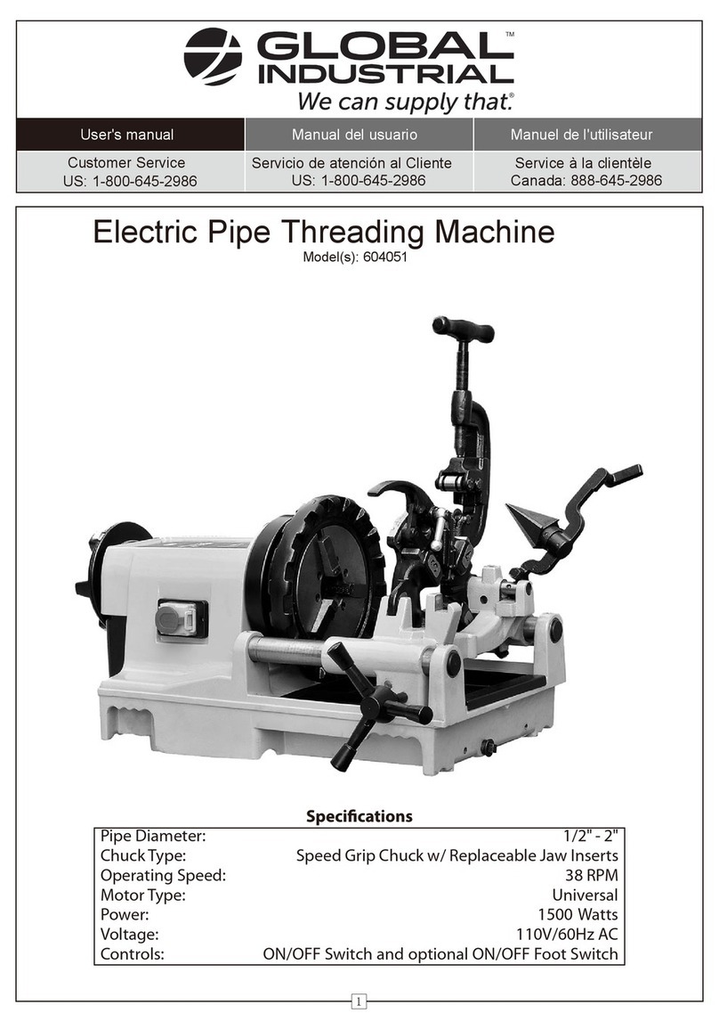
Global Industrial 604050 User manual

User's manual Manual del usuario Manuel de l'utilisateur
Customer Service
US: 1-800-645-2986
Servicio de atención al Cliente
US: 1-800-645-2986
Service à la clientèle
Canada: 888-645-2986
Pipe Diameter: 1/2" - 2"
Chuck Type: Speed Grip Chuck w/ Replaceable Jaw Inserts
Operating Speed: 38 RPM
Motor Type: Universal
Horsepower: 2 HP
Voltage: 110V/60Hz AC
Controls: FOR/OFF/REV Switch and ON/OFF Foot Switch
1
Model(s): 604050
Electric Pipe Threading Machine

Manual Pipe Threader
2
SAFETY INSTRUCTIONS
1. Keep your work area clean and well lit. Always keep the work area free of obstructions, grease, oil, trash,
and other debris.
2. Never operate this machine in the presence of ammable liquids, gases, or dust. Power tools create sparks
which may ignite the dust or fumes.
3. Keep bystanders, children, and visitors away while operating this machine. Distractions can lead to serious
injury or property damage. Protect others in the work area from debris such as chips and sparks. Provide
barriers or shields as needed.
4. Never leave pipe threader unattended while running.
5. Do not touch grounded surfaces such as pipes, radiators, ranges, and refrigerators when operating on
electrical components. There is an increased risk of electric shock if your body is grounded.
6. Do not expose the machine to water. Water entering a power tool will increase the risk of electric shock.
7. Grounded tools must be plugged into an outlet properly installed and grounded in accordance with all
local codes and ordinances. Never remove the grounding prong or modify the plug in any way. Do not use
adapter plugs. Check with a qualied electrician if you are unsure if the outlet is properly grounded. If the
tools should electrically malfunction, grounding provides a low resistance path to carry electricity away
from the user.
8. Do not use pipe threader if foot switch or FOR/OFF/REV switch does not work. Cease operation and repair
switch(es) or replace pipe threader. Do not use machine if foot switch cover is damged or missing.
9. Secure pipe threading machine to bench or stand. Support long heavy pipes with pipe supports to
prevent tipping or bending.
10. Do not touch pipe while pipe threading machine is running, doing so can cause serious personal injury
or permanent damage to the tool or workpiece. Allow the machine to come to a complete stop before
wiping or cleaning any surfaces.
11. Do not use the machine to make or break pipe ttings, this is not an intended use of the pipe threader and
can cause serious personal injury.
12. Ensure that the workpiece is properly secured and the chuck is tight before turning on the pipe threader.
13. Keep the Power Cord away from heat, oil, sharp edges, or moving parts. Cease operation and replace
Power Cords immediately if damaged.
14. Disconnect power cord before making any adjusments, maintenance, or storing the machine.
15. Avoid Accidental start-ups, make sure FOR/OFF/REV switch is in the "OFF" position before plugging in the
power cord.
16. Never use this machine when tired or under the inuence of drugs, alcohol, or medication.
17. Dress properly. Do not wear loose clothing or jewelry. Contain long hair. Keep your hair, clothing, and
gloves away from moving parts. Loose clothes, jewelry, or long hair can be caught in moving parts and
may cause serious personal injury.
18. Use safety equipment, pipe threading machines can produce sharp chips which can cause permanent eye
damage if lodged in the eye. Wear ANSI Z87+ safety glasses or goggles for protection.
19. Do not use third party or aftermarket accessories, they may impare operation of the pipe threader or
malfunction during normal use.
20. Maintain all labels and nameplates on the machine so that they are clearly visible and legible.
3
Manual Pipe Threader
OPERATION INSTRUCTIONS
To install pipes,
1. Swing the cutter, reamer and die head out of the way so that you can access the power drive.
2. Insert the pipe into the Power Drive so that the end to be worked or the cutting mark is located about 12
inches to the front of the speed chuck jaws. If the pipe is being cut to length, mark at the desired length.
3. Insert workpieces less than 2 feet long through the front of the machine. Insert longer pipes through
either end so that the longer section extends out past the rear of the Power Drive.
4. Tighten the rear centering device around the pipe by using a counterclockwise rotation of the
handwheel at the rear of the Power Drive. This prevents movement of the pipe that can result in poor
thread quality.
5. Secure the pipe by using repeated and forceful counterclockwise spins of the speed chuck handwheel at
the front of the Power Drive. This action “hammers”the jaws tightly around the pipe.
Die head is adjustable. To adjust die size, turn throwout lever to "OPEN" position and loosen clamp lever,
then rotate size bar so that desired size lines up with index line.
To cut pipe threads,
1. Check that the dies are the proper type and are not worn or chipped.
2. Lower the die head into position. Make sure the cutter and reamer are swung out of the way.
3. Adjust die head to the proper size.
4. Turn the throwout lever to the "CLOSED" position.
5. Set directional switch the the "FOR" (forward) position. Press the foot switch to begin turning the pipe
and apply thread cutting oil.
6. Apply more thread cutting oil to dies. Use carriage lever to engage dies with pipe and begin cut.
Continue to oil workpiece as needed throughout cut.
7. When cut is nished, turn throwout lever into "OPEN" position to retract dies. Move die assembly back
using carriage lever and swing die head up to access the pipe threads.
To replace dies if they are worn or damaged,
1. With machine unplugged, remove die head. Lay die head on bench with numbers face up.
2. Flip throwout lever to OPEN position.
3. Loosen clamp lever.
4. Lift tongue of clamp lever washer up and out of slot under size bar. Move throwout lever all the way to
the OVER direction indicated on size bar (in direction of CHANGE DIES arrow on rear of cam plate), then
pin tongue of clamp lever washer behind lip of die head so that the assembly locks in place. Remove
dies from die head. Note that dies feature a number and a line mark. Die numbers 1 through 4 on the
dies must agree with those on die head. Insert new dies up to line mark. Turn the throwout lever to the
"CLOSE" position to capture the dies.
5. Unpin clamp lever washer tongue and drop it back into
the slot under the size bar.
6. Adust die head size bar until the index line on lock screw
or link is aligned with proper size mark on size bar. For bolt
threads, align index line with BOLT line on size bar, then
tighten clamp lever to secure.
7. If oversize or undersize threads are required, set the index
line in direction of OVER or UNDER size mark on size bar.
8. Place die head back in machine.

4
fManual Pipe Threader
To cut pipe,
1. Make sure the die head and reamer are swung out of the way.
2. Hold the pipe cutter just above the pipe and use carriage
lever to line up cutter wheel with mark on pipe, then rest the
cutter on the pipe.
3. Tighten cutter feedscrew handle while keeping the cutter
wheel aligned with the mark.
4. Set directional switch the the "FOR" (forward) position. Press
the foot switch to begin turning the pipe and apply coolant.
5. Holding the cutter feedscrew handle with both hands,
tighten slowly and continuously until the pipe is cut. Do not
force the cutter into the workpiece.
6. When cut is nished, swing cutter up to access the cut pipe.
To ream pipe,
1. Make sure the cutter and die head are swung out of the way.
2. Lower reamer arm down into position.
3. Move reamer forward by opening reamer lock latch and
sliding reamer toward pipe until latch reengages.
4. Set directional switch the the "FOR" (forward) position. Press
the foot switch to begin turning the pipe and apply coolant.
5. Move reamer into pipe and begin reaming by pushing
carriage lever with right hand.
6. When reaming is complete, move carriage lever back. Open
reamer lock latch and retract reamer until latch reengages,
then return reamer to the UP position.
To remove pipe,
1. Set directional switch to "OFF" position.
2. Use repeated and forceful clockwise spins of the speed chuck handwheel at the front of the Power Drive
to release the workpiece from the speed chuck jaws.
3. If necessary, loosen the rear centering device using a clockwise rotation of the handwheel at the rear of
the Power Drive.
4. Slide the workpiece out of the Power Drive, keeping a rm grip on the workpiece as it clears the Power
Drive. To avoid injury from falling parts or equipment tip-overs when handling long workpieces, make
sure that the end farthest from the Power Drive is supported prior to removal.
5. Clean up any oil spills or chips on the ground surrounding the device.

MAINTENANCE INSTRUCTIONS
Jaw inserts
• Clean jaw inserts daily with a wire brush.
• If jaw inserts fail to hold pipe or rod or are otherwise worn or damages, replace them
NOTE, even if only one jaw insert is damaged, replace the entire set to ensure workpiece will be properly
held throughout cutting procedures.
• To replace jaw inserts, place a screwdriver in the insert slot and turn 90 degrees in either direction, then
place insert sideways on locking pin and press down as far as possible
• Hold insert down rmly with screwdriver. Turn until teeth face up.
Lubrication
• Use cup grease to lubricate shaft bearings every 2 to 6 months depending on use. Grease ttings are
located at both ends of each carriage shaft.
Motor
• Check motor brushes every 6 months. Replace when worn to less than 1/2".
• If commutator is worn, the outer dimension of the commutator should be turned and the mica should
be undercut before replacing brushes. This should only be done by qualied repair personnel.
• If motor is otherwise damaged, replace motor. To remove the motor, unplug the motor receptacle from
the switch box, remove the 2 screws holding the motor, and loosen the screw in the power drive body at
the neck of the motor.
WARNING
Before performing any inspection,
cleaning, or maintenance procedures,
make sure the machine's power switch
is in the "OFF" position and that the
power cord is unplugged.
Manual Pipe Threader
5
Table of contents
Other Global Industrial Industrial Equipment manuals

Global Industrial
Global Industrial 604051 User manual

Global Industrial
Global Industrial HEPA 641754 User manual

Global Industrial
Global Industrial 168110 User manual

Global Industrial
Global Industrial B237006 User manual

Global Industrial
Global Industrial FM180K User manual

Global Industrial
Global Industrial 647108 User manual

Global Industrial
Global Industrial 670613 User manual