GLOBAL PLASMA SOLUTIONS iMOD Instruction manual

012019-GPSIMOD-IOM REV C
GLOBAL PLASMA SOLUTIONS
iMOD
Installation
Operation &
Maintenance
Manual
10 Mall Terrace, Building C
Savannah, GA 31406
(912) 356-0115 Phone
www.globalplasmasolutions.com

012019-GPSIMOD-IOM REV C
DO NOT POWER UNTIL INTERNAL VOLTAGE SELECTOR SWITCH IS CONFIRMED IN THE CORRECT POSITION!!!!!!
INSTALLATION
Thank you for purchasing a GPS-iMOD system from Global Plasma Solutions (GPS). The GPS-iMOD is a revolutionary product in
the air purification industry. Unlike traditional ionization systems utilizing glass tubes, the GPS-iMOD is manufactured from
high quality components to prevent wear, replacement and ozone generation. The system is designed to provide a long,
trouble free life.
HARDWARE PROVIDED BY GPS
Before you start, confirm the contents of your shipment contains all the parts ordered. Each GPS-iMOD system will consist of
the following minimum components:
1. (1) GPS-iMOD 15 watt power supply with multi-voltage input: (24VAC / 0.5A) (120VAC / 0.12A) (208-240VAC / 0.065A).
2. (1) GPS-iMOD 6’ flexible power cable with connectors and first electrode on the bar already attached. Custom length cables
may have been ordered and lengths may vary by application. More than 1 may be provided based on AHU size.
3. GPS-iMOD 6 inch modular sections provided per quantities ordered to achieve overall desired ionization bar length.
4. (1) End cap per completed modular bar. End cap inserts into the last modular section of the bar.
5. A minimum of (2) mounting magnets per bar for securing the GPS-iMOD to the cooling coil inlet or filter rack. Secure
magnets to the modular sections. Magnet quantity provided will increase based on overall bar length.
6. Nylon screws and nuts for securing magnets to the front or back of the iMOD sections and metal screws for securing
magnets to the top of the iMOD sections where the bar can be mounted to the ceiling of an air handler.
HARDWARE REQUIRED BY OTHERS
1. Self tapping sheet metal screws
2. Electric wiring, jbox or receptacle to provide power to the GPS-iMOD power supply, optional air flow switch, optional door
switch, optional remote mounted ion detector sensor, or optional NEMA enclosure for power supply. Note: optional items may
be included based on the items quoted or provided in the purchase order.
INSTALLATION LOCATION
GPS recommends mounting the GPS-iMOD downstream of a MERV 6, 30% particulate filter to prevent unnecessary build-up of
particulate on the carbon fiber needle tips. Below is a list of locations to mount the GPS-iMOD in the preferred order.
1. The optimal location to mount the GPS-iMOD is between the particulate filter and the cooling coil. Mounting the GPS-iMOD
in this location will prevent particulate build-up and the GPS-iMOD mounted before the cooling coil will prevent bacteria, virus
and mold from breeding on the cooling coil as the ions will be pulled through the coil with the air flow.
2. Downstream of the particulate filters and the cooling coil in a location where condensate from the coil or a humidifier will
not completely saturate the bar. While the modular bar is waterproof, if the carbon fiber brushes are saturated with water
from condensate, ionization output will be reduced.
3. Before the particulate filters. Please note, if the bar is mounted before the particle filters, the ionization will not go past the
particle filters. In healthcare applications, 2 sets of bars are suggested, one set on the coil inlet and one after the final filters.

012019-GPSIMOD-IOM REV C
MECHANCIAL INSTALLATION
For standard IAQ applications, there should be (1) GPS-iMOD on each cooling coil up to 60 inches in height. The GPS-iMOD(s)
may be located closer to each other than 60 inches, but 60 inches is the maximum height they should be placed apart. The bar
should be assembled such that the entire finned width of the cooling coil is covered.
1. Once the location has been determined, assemble the modular sections by inserting the male thread into the female
receiver of the first modular section already attached to the power entry cable and tighten until the modular housings are
securely butted to each other. See Figure 1 below for appearance of correct assembly. Please note, it normally takes 3-4
complete revolutions to assemble properly. Continue this process until they are all assembled to the desired length.
Due to the manufacturing process, not all bars will screw together and line up with the brushes pointing in the same direction,
without using excessive force that could damage the module. Below are detailed directions to assemble the bars regardless of
threading.
FIGURE 2
A. When the sections do not align and are more than 90 degrees from alignment, but the pieces are tight with no gap as
shown in Figure 1A, disassemble the section and place a nylon gasket (provided by GPS) between the two sections as shown in
Figure 3.
FIGURE 1A. Proper Assembly – NO GAP
FIGURE 1B. Bad Assembly – GAP
VISIBLE

012019-GPSIMOD-IOM REV C
FIGURE 3
B. Once the gasket is placed over the male end of the device, twist the sections together until the parts are snug and the
carbon fiber brushes are pointing in the same direction. Please note, once the bars are assembled, there should be no
“wobble” between the sections.
3. Once the last modular section is added, push the nylon connector into the female receiver. It will “snap” into place with
sufficient pressure. Refer to Figure 4.
FIGURE 4
4. The GPS-iMOD modular sections can be mounted using the included magnets and hardware or they can be mounted using
sheet metal screws, provided by others, through the integral molded brackets. There should be at least one magnet mounted
on each end of the bar assembly and depending on length of bar, additional magnets or sheet metal screws may be required.
Refer to Figure 5. Nylon screws and nuts will be provided by GPS for mounting the magnets to the front or back of the bar.
FIGURE 5
4. When mounting the GPS-iMOD, the bottom of the GPS-iMOD should be level with top of the finned surface area of the coil
as shown in Figure 7 with the carbon fiber brushes pointing towards the floor. Keep all metal away from carbon fiber brushes.
The ionization bar should always be mounted on the air entering side of the cooling coil. Mounting the bar on the leaving side
of the coil (drain pan and wet side) will not keep the coil clean. The GPS-iMOD power head may be rotated to provide the best
power cord routing based on the installation. Refer to Figure 6. When more than one bar is required per coil, mount the
second bar half way down the coil with the needles pointing towards the floor. Please note, the installing contractor will have
to provide a piece of metal angle across the face of the coil to attach the GPS-iMOD, if the coil finned surface area is over 3 feet
wide.

012019-GPSIMOD-IOM REV C
FIGURE 6
FIGURE 7
Power Supply Installation and Wiring – WARNING – DO NOT CONNECT POWER UNTIL VOLTAGE SELECTOR
SWITCH INSIDE HOUSING IS CONFIRMED IN THE CORRECT POSITION FOR THE PRIMARY POWER BEING APPLIED!!!
The GPS-iMOD system requires a total of 15 watts to power up to (6) GPS-iMODs at any length. The power supply will accept
24VAC, 115VAC or 208-240VAC at 50HZ or 60HZ. CAUTION!! The power supply has an internal voltage selector switch set to
115VAC from the factory, refer to Figure 8. If 24VAC or 208-240VAC is required, move the selector switch to the proper
position as shown on the circuit board or inside cover of the power supply lid. DO NOT APPLY POWER until the switch
position matches the power supplied. Based on voltage input or local electric codes, the 3 prong plug may be cut off and the
three wires are as follow: White = Neural, Black = 24V, 110V or 208-240V (based on switch position) and Green = Ground.
The power supply may be mounted to the internal wall of the air handler or the external wall of the air handler.
1. Find a suitable location within reach of the high voltage cable extending from the GPS-iMOD. Remove the four screws in the
lid of the power supply.
2. Mount the power supply to the wall using sheet metal screws through the mounting tabs provided on the power supply.
Rotate connector arm up or leave down as
required for installation

012019-GPSIMOD-IOM REV C
3. One opening in the high voltage (HV) section will be left open for attachment of the HV wire. Refer to Figure 9. Based on
the jobsite specific wiring route, access to the right, left or top side may be desired. Remove the plug from the port desired and
fill the port not used with the spare plug. DO NOT RUN HIGH VOLTAGE INPUT WIRES THROUGH THE CONTROL PORTS AND
DO NOT RUN CONTROL WIRING THROUGH HIGH VOLTAGE (HV) PORTS! REFER TO FIGURE 8, LEFT PHOTO.
FIGURE 8
4 CONTROL PORTS 6 HV PORTS VOLTAGE SELECTOR SWITCH
FIGURE 9 HV SCREW AND NUT TOP NUT REMOVED FINAL CONNECTION
4. Remove the top nut from the HV screw. DO NOT REMOVE THE BOTTOM NUT! Remove the plastic nut from the end of the
high voltage cable. Next, push the HV wire through the desired port and place the plastic nut back over the HV cable. Place the
electrical eye connector over the HV screw and tighten down the top nut to secure. If there are multiple bars connected, place
all electrical eye connectors under the top nut prior to tightening. Push the HV connector into the HV port and tighten the
plastic nut to secure in place. Once all connections are made, replace lid or connect the control wiring.

012019-GPSIMOD-IOM REV C
CONNECTION TO BMS
1. The GPS-iMOD has internal ionization output sensing. Integral alarm “dry” contacts will close when the system is on and
operating properly. To tie into the BMS for remote monitoring, use 18/2 twisted pair, SHIELDED, plenum rated cable and
connect to the BMS ALARM contact terminals. Connect the cable shield to the ground terminal as shown in Figure 10. The
terminal block may be removed for ease of wiring. Keep the control wiring as far from the HV wiring as possible. DO NOT
RUN BOTH CABLES TOGETHER AND DO NOT ZIP TIE CONTROL WIRING TO FLEXIBLE HV CABLES!
FIGURE 10
FIGURE 11
CONNECTION OF OPTIONAL GPS-iDETECT-P
1. Remove the red jumper wire between C and NO on the GPS-iDetect terminal block.
2. Using 300V, 18/4, plenum rated, SHIELDED cable, wire between the GPS-iDetect-P power and normally open terminals and
the GPS-iMOD power supply GPS-iDetect-P terminal block as shown in Figure 10. Ground the 18/4 SHIELD to the ground
terminal on the GPS-iDetect-P terminal strip shown in FIGURE 10. Please note, only ground ONE end of the shielded cable. Do
not ground the end connected to the GPS-iDETECT-P sensor. DO NOT RUN CONTROL WIRING WITH HV CABLES!
3. Mount the GPS-iDetect-P using the included 1” coated pipe clamp and secure to a GPS-iMOD section as shown in Figure 11
using a nut and bolt.
4. When the GPS-iDetect-P senses output, the “Plasma On” light will illuminate on the front panel of the power supply and the
BAS Alarm Contacts will close. When using the GPS-iDetect-P in conjunction with the GPS-iMOD power supply, always connect
to the BMS using the BMS Alarm Contacts, not the contacts on the GPS-iDetect-P.
Ground terminal for BAS 18/2 Shield. Please
note, only ground one end of shielded cable!

012019-GPSIMOD-IOM REV C
OPERATION
1. Once the voltage selector switch has been set, HV wire(s) connected and bar(s) mounted, turn the power switch to the “ON”
position. When the switch is turned “On” the “Power On” light will illuminate letting the end user know power is supplied and
the GPS-iMOD system is energized. Note: If a door switch, fan interlock switch or air flow switch are in series with the power,
the system may not turn on until all safeties are closed. When power is supplied and the internal or optional remote mounted
GPS-iDetect-P is sensing output, the “Plasma On” light will illuminate.
2. The internal BAS Alarm Contacts will close proving system operation to the BMS.
2. Using a standard non-contact voltage meter, one can place it near the ion needles and prove there is ion output. An
optional ion meter can be purchased from GPS and actual values may be measured. A permanent mount ion detector with BAS
interface may be provided as an option for 24/7 output monitoring.
STARTUP/TESTING
1. Once the entire system is mounted and wired, energize the system by turning the on/off switch to the “on” position. The
green power “ON” LED and “PLASMA ON” LED should illuminate. If the PLAMA ON does not illuminate, confirm the red jumper
is installed between C and NO on the GPS-iDetect-P terminal block. If an external sensor is used, confirm it is on and operating.
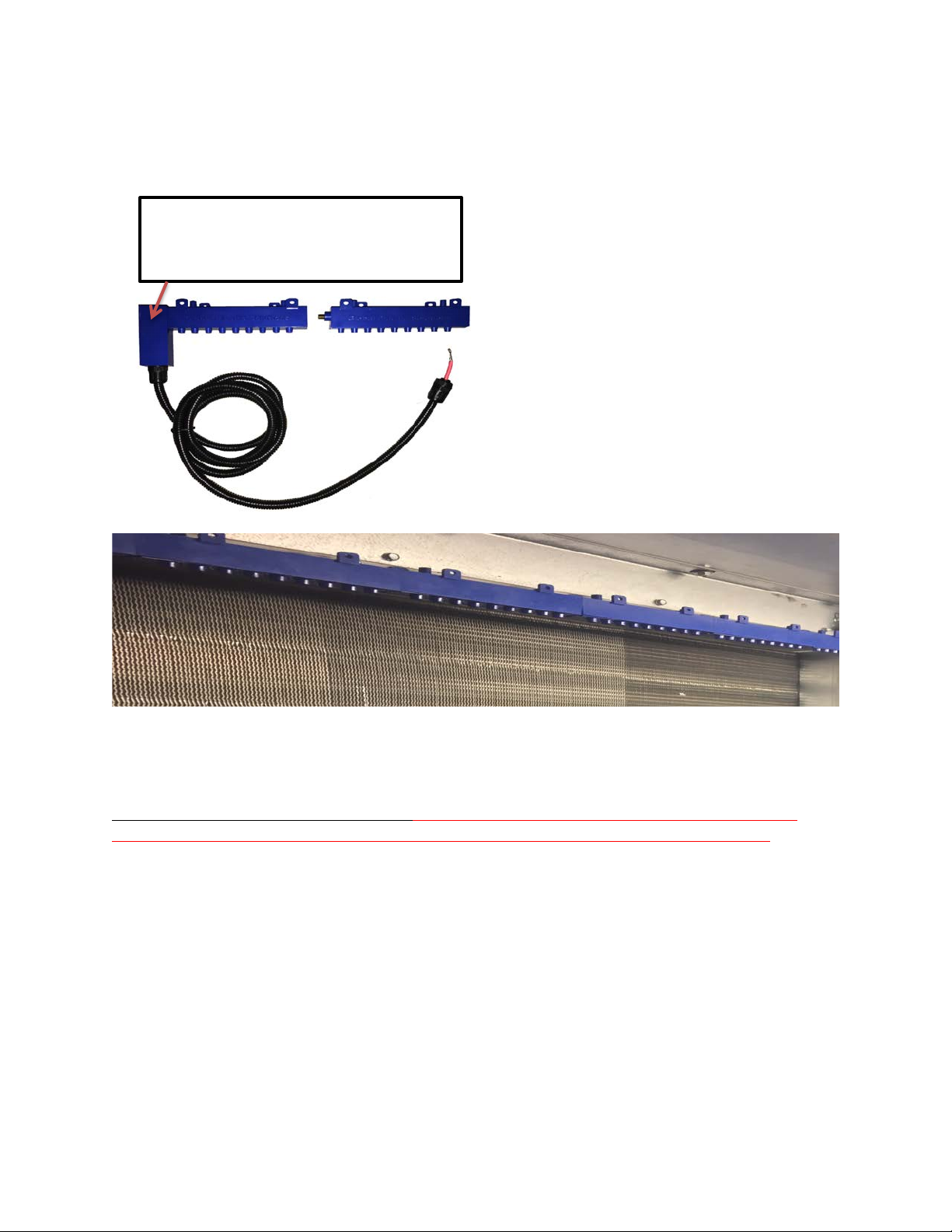
2. Using a high voltage probe similar to a BK Precision Plus 28A, connect the probe to a multi-meter, connect the ground clamp,
and measure the AC high voltage (AC not DC) at the 6 inch modular stingers. Insert the tip of the probe into one of the brush
clusters and confirm the voltage is greater than 4,000 VAC. Please note, most probes provide a 1000:1 step down. As an
example, a display of 4.0 would be 4.0 x 1000 = 4,000 VAC. The typical range of voltage is 4,000VAC to 7,000VAC and the actual
voltage will depend on the length and quantity of bars attached.
MAINTENANCE
The GPS-iMOD system has been designed for minimum maintenance. Below are the steps to ensure a long trouble-free life:
1. On an annual basis, turn off power and use isopropyl alcohol and a nylon (wire free) brush to gently clean the needles.
2. Use a soft cloth with isopropyl alcohol and wipe any debris off the GPS-iMOD outer bar and spaces between needle
housings.
3. Note, in smoking applications, the GPS-iMOD will require more frequent cleaning based on the filter efficiency prior to the
GPS-iMOD system.
TROUBLESHOOTING
1. Power supply “Power On” light not illuminated when the power switch is in the “On” position.
1A. Check that all safeties are closed and there is primary power applied to the power supply. If light will still not illuminate,
remove power and energize after five minutes. The GPS-iMOD system uses an internal auto-reset circuit breaker. Either a
voltage surge or high temperature/load condition can trip the circuit breaker. If the “Power On” light is off and the “Plasma
On” light is “On”, the “Power On” light may have burned out. Contact your local Representative or the GPS factory to have
your power supply repaired or replaced.
2. No Ionization Output.
2A. Confirm the power supply is operating properly as shown in step 1A above. Confirm the HV cables are inserted and
secured properly. Confirm the needles are clean and free of debris.
Table of contents
Other GLOBAL PLASMA SOLUTIONS Air Cleaner manuals
Popular Air Cleaner manuals by other brands

GeneralAire
GeneralAire GUV-2000 Installation & maintenance instructions

AtmosAir
AtmosAir Matterhorn 880 Installation, operation and maintenance guide

activTek
activTek PURECLOUD owner's manual

Fedders
Fedders 120V/60Hz Installation, operation and maintenance manual

asecos
asecos HF.EA.8678 operating instructions

InovaAir
InovaAir AirClean V20 user manual