Global 293042 User manual

Blower HeElectric
Models: 653561 653560 6535
653558 653562 246067
g
globalindustrial.ca
Assembly Instructions Instrucciones de Ensambla
Customer Service
US: 1-800-645-2986
Servicio de atención al Clien
México: 01.800.681.6940
eater
559
DE CFDistribucion Industrial Globales S DE RL
aje
nte
ectives d’assemblageDir
Service à la clientèle
Canada: 888-645-2986
THESE
ONS
050117
1
READ & SAVE
INSTRUCTIO
Wall Mount Models: 653566 653567 653568
653569 246068
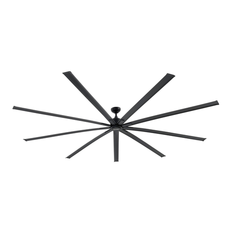
HVLS BLDC Fan
READ & SAVE THESE
INSTRUCTIONS
Models:293042 293043 293044
293045 and 293046

HVLS BLDC Fan User’s Manual
2
GENERAL SAFETY INSTRUCTIONS
Read instructions carefully before assembling or installing
your fan. It is important that you observe all safety information
to help prevent personal injury and/or property damage.
TO REDUCE THE RISK OF SHOCK, THIS FAN
MUST BE INSTALLED WITH A GENERAL USE
ISOLATING WALL CONTROL/SWITCH.
1.Installation work and electrical wiring must be performed in
accordance with the requirement of NEC and CEC by
authorized personal only.
2.All wiring and installation procedures must satisfy National
Electrical Codes (ANSI/ NFPA 70) and Local Codes.
3.Use this fan only in the manner intended by the manufacturer.
This fan is intended for permanent installation and to be used
for circulation only.
4.The secondary support cable included with the fan must be
properly connected.
5.To Reduce The Risk Of Personal Injury, Do Not Bend The Blade
Brackets When Installing The Brackets, Balancing The Blades,
Or Cleaning The Fan. Do Not Insert Foreign Objects In Between
Rotating Fan Blades..
6.Before servicing or cleaning unit, switch power off at service
panel and lock service panel disconnecting means to prevent
power from being switched on accidentally. When the service
disconnecting means cannot be locked, securely fasten a
warning device, such as a tag, to the service panel.
7.Be careful of the fan and blades when cleaning, painting, or
working near the fan. Always turn off the power to the ceiling
fan before servicing.
8.Ceiling fans without guards are to be installed at least 3.05
Meters (10 Feet) above the floor with adequate clearance
between blades and adjacent walls, furnishings, etc.
9.When mounted in cathedral ceiling, blade tips should be at least
1 foot from the angled roof line or air turbulence may cause the
fan to sway.
10.The supporting beam must be capable of holding at least
600 KGS.
11.All set screws must be checked, and retightened where
necessary, before installation.
To Reduce The Risk Of Personal Injury, Do
Not Bend The Blade Brackets When Installing
The Brackets, Balancing The Blades, Or
Cleaning The Fan.
To Reduce The Risk Of Fire Or Electric Shock,
Do Not Use This Fan With Other Types Of
Solid-State Speed Control Devices.
Disconnect the fan from the power supply
before any servicing.
Do not insert foreign objects in between
rotating fan blades.
Model 293042 293043 293044 293045 293046
Size(ft) 12 14 16 18 20
Voltage(V) 240 240 240 240 240
Frequency(Hz) 60 60 60 60 60
Wattage(W) 680 600 820 930 810
RPM 20-88 20-65 20-78 20-65 20-55
AMPS(A) 4.8 4.3 5.7 6.3 5.6
Hanger Rod Dimensiond(inch) 20 20 60 60 60
Blades 6 6 6 6 6
Net Weight(KG) 75 78 115 118 123
Certification UL,cUL UL,cUL UL,cUL UL,cUL UL,cUL
SPECIFICATION
For commercial and industrial use only !
HVLS BLDC Fan
User’s Manual
3
REF QTY DESCRIPTION
1 1 I-Beam Mounting Bracket
2 2 I-Beam Mounting Spacer 1
3 2 I-Beam Mounting Spacer 2
4 1 Hanger Rod
5 1 Fan Blade Holder
6 1 Motor Hanger Assembly
7 1 Motor
8 6 Fan Blade
9 6 Fan Blade Cap
10 6 Fan Blade Safety Gasket
11 1 Motor Cap
12 6 Fan Blade Cap Spacer
13 1 Control Box
ON
FWD
REV
OFF
SPEED
OVERLOAD
PROTECTION
PRESS TO
RESET
1
2
3
4
6
5
8
7
11
9
12
13
10
PARTS OF THE FAN

HVLS BLDC Fan User’s Manual
4
H1 H2
H3
H4
H5
H6
H8
H9
H13 H14 H15
H16
H17 H18 H19 H20
H21 H22 H23 H24
H7
REF QTY DESCRIPTION
H1 1 4x16AWG Interconnecting Cord
H2 5 Safety Steelcable Ф6mmx10m
H3 4 Turnbuckle
H4 30 Steelcable lock
H5 6 Hex Screw M14x50mm
H6 6 Hex Screw M12x50mm
H7 2 Hex Socket Screw M14x120mm
H8 2 Hex Socket Screw M14x100mm
H9 2 Hex Socket Screw M12x90mm
H10 6 Hex Screw M8x70mm
H11 12 Hex Screw M8x45mm
H12 12 Hex Screw M6x35mm
H13 20 Flat Washer 14mm
H14 6 Flat Washer 12mm
H15 30 Flat Washer 8mm
H16 12 Flat Washer 6mm
H17 4 Spring Washer 14mm
H18 6 Spring Washer 12mm
H19 6 Spring Washer 8mm
H20 4 14mm Nut
H21 6 Self-tapping Nut 14mm
H22 2 Self-tapping Nut 12mm
H23 12 Self-tapping Nut 8mm
H24 12 Self-tapping Nut 6mm
H25 4 Plastic Anchor
H26 4 Screw ST4.2x50mm
PARTS OF THE FAN
H25 H26
H12
H11
H10

User’s Manual
5
HVLS BLDC Fan
Dimensions(inch)
D
H
Model D H
293042 144 32
293043 168 32
293044 192 73
293045 216 73
293046 240 73
INSTALLATION INSTRUCTIONS
To avoid possible electrical shock, be sure
electricity is turned off at the main fuse box
before hanging. (Figure 1)
NOTE: If you are not sure if the outlet box is grounded,
contact a licensed electrician for advice, as it must be
grounded for safe operation.
Figure 2
10
The fan must be hung with at least 10´
of clearance from floor to blades. (Figure 2)
To Reduce The Risk Of Fire, Electric Shock,
And Injury To Persons, Ceiling-Suspended
Fan Must Be Installed With Blades That Are
Marked On Their Cartons To Indicate The
Suitability With This Model. Other Blades
Cannot Be Substituted.

User’s Manual
6
HVLS BLDC Fan
1. Loosen the 12 screws and washers which on the motor hanger
assembly.
2. Install the fan blade holder to the motor assembly with screws
and washers as below picture, make sure tighten all the screws
and washers.
5
H6
H18
H14
H10
H19
H15
H6
H18
H14
H10
H19
H15
Screws and washers must be installed in pairs.
(H10)M8x70mm Screw must be installed with (H19) 8mm spring
washer and (H15) 8mm flat washer.They should be tighten with
36N.M torgue.
(H6)M12x50mm Screw must be installed with (H18) 12mm
spring washer and (H14) 12mm flat washer.They should be
tighten with 135N.M torgue.
3. Install the I-Beam mounting bracket to the I-Beam with the I-
Beam mounting spacer 1&2 to the (H20) 14mm nuts, (H21) 14mm
Self-tapping Nut, (H17)14mm Spring Washer, (H13) 14mm flat
washer and (H5) M14x50mm screw, make sure all the screws and
washers are tighten with 135N.M torgue.
3
2
1
H21
H20
H17
H13
H5
H13
4. Install the hanger rod to the mounting bracket with (H7)
M14x110mm screws, (H13)14mm flat washers and (H21)14mm
self-tapping nuts.
4
H7
H13
H21
H13

User’s Manual
7
HVLS BLDC Fan
H4
H2
Reliable Fixing Structure
A
H3
H4
45
H4
H3
H2
5.A.Encircle one end of the (H2) steel cable around the reliable fixing structure, then attach 3 (H4) steel cable lock onto the
cable for secure installation.
B.Hook the (H3) turnbuckle to the holes in the sheet of hanger rod , and connect the other end of the (H2) safety steel cable.
Attach the (H4) steel cable lock onto the cable for secure installation. Repeat step A and B, install all 4 steel cable.
B
Sheet of the
hanger rod
Loosen the nuts of the (H4) steel cable lock, attach
onto the cable and tighten them.

User’s Manual
8
HVLS BLDC Fan
6. Pass the motor lead wire through the slot of the hanger rod, and
tighten the motor assembly to the hanger rod with (H8)
M14x100mm screw, (H9) M12x90mm screw, (H13) 14mm flat
washer, (H21) 14mm self-tapping nut and (H22) 12mm
self-tapping nut.
H8
H9
H21
H22
H13
Motor Lead
Wire
H4
H2
H4
7.Pass the (H2) safety steel cable through the motor safety hole,
encircle one end of cable , and attach the (H4) steel cable lock
onto the cable for secure installation.
Pull the other end of the steel cable into the center hole of the
hanger rod and out through the hanger rod , encircle the cable
around the I-beam, and then attach the (H4) steel cable lock
onto the cable for secure installation.
8.Install the fan blade cap and fan blade cap spacer to the fan
blade with (H12) M6x35mm screw , (H16) 6mm flat washer and
(H24) 6mm self-tapping nut. Repeat this step for all 6 fan blades.
9
12
H12
H16
H24
9. Install all the fan blade assembly to the fan blade holder. Then
place the fan blade safety gasket (10) onto the fan blade side by
side, align the screw holes and tighten with (H11) M8x45mm
screws, (H15) 8mm flat washer and (H23) 8mm self-tapping nut.
10
H15
H11
H23
Motor Safety
Hole

ELECTRICAL WIRING
1. Open the junction box cover on the hanger rod, and connect
the motor lead wire and 4x16AWG interconnecting cord to the
terminal as shown below, make sure tighten all the terminal
screws.
U
V
W
G
U
V
W
G
U
V
W
G
Junction Box
4x16AWG
Interconnecting
Cord
Motor Lead
Wire
User’s Manual
9
HVLS BLDC Fan
10. Rotate the motor cap (11) to the fan assembly until tighten.
11
11.Install the (H25) plastic anchor to the wall at the distance
shown as below. Then install the control box to the plastic anchor
with (H26) M6x60mm screw.
Warning: Do not install closer than 1 foot (0.3 m) from both sides
of the control box to any adjacent surface/wall.
180mm
330~335mm
H26 H25
2.Open the control box wiring cover, and connect the fire alarm
wire, 4x16AWG interconnecting cord and power-supply
conductor as shown below.
ON
FWD
REV
OFF
SPEED
OVERLOAD
PROTECTION
PRESS TO
RESET
MOTORPOWER
FIRE
L1L2 G V WG U
-+
FIRE
ALARM
G
L1 L2
+
_
U V WG
ON
FWD
REV
OFF
SPEED
OVERLOAD
PROTECTION
PRESS TO
RESET
MOTORPOWER
FIRE
-+
G
L1 L2
+
_UVWG
G
L1L2
UVWG
Connect the lead wire of the fire alarm
to the terminal 1, and then connect the
4x16AWG interconnecting cord and the
power-supply conductor to the terminal
2 as below picture.
Lead Wire of
Fire Alarm
4x16AWG
Interconnecting Cord
Power-Supply
Conductor

User’s Manual
10
HVLS BLDC Fan
WIRING DIAGRAM
G1
L1
L2
POWER
240V/60Hz
L1
L2
G1
PCBA
control
+
_
Fire PCB
Fire
U
V
W
MOTOR
U
V
W
G2
4x16AWG WIRE
G2
This wiring diagram is for all models.
Volt: 240 V
Frequency: 60 Hz
OPERATING INSTRUCTIONS
Before turning on or restarting the fan, you
must confirm that all the fan blades are
completely stationary. Never turn on the fan
while the fan blades are still moving, otherwise
the motor may be damaged.
A
BCD E
SPEED
REV
FWD
ON
OFF
OVERLOAD
PROTECTION
PRESS TO
RESET
A LED Display
B Overload Protection
C Speed Switch
D Direction Rocker Switch
E Power Switch
1. Press the Power Switch on, the LED display will light up and work
state show [STAND BY].
2. Press the Direction Rocker Switch to [FWD],
and turn on the Speed Switch slowly. The LED
display will show the current and speed. The fan
blade rotates counterclockwise and the air will
blow down.
A downward air flow creates a cooling effect.
This allows you to set your air conditioner on a
higher temperature setting without affecting your
comfort.
Press the Direction Rocker Switch to [REV],
and turn on the Speed Switch slowly.The LED
display will show the current and speed. The fan
blade rotates clockwise and the air will blow up.
An upward airflow moves warm air off the ceiling
area. This allows you to set your heating unit on
a lower setting without affecting your comfort.
Note: When the fan blades start rotating, a little sound and vibration
is normal. But if the motor makes a loud noise, please press
the Power Switch off immediately. Wait until the fan blades are
completely stationary, and check out each part of the fan’s
installation, make sure that the fan is ok. Then repeat the
steps above.
3. To shutdown the fan , please turn off the Speed Switch slowly.
Wait until the fan blades are completely stop, and then press the
Power Switch off.
Parts of the Control Box
REV
FWD

User’s Manual
11
HVLS BLDC Fan
2.Clean the fan periodically to help maintain the appearance. Do not
use water when cleaning. This could damage the motor, or
possibly cause electric shock.
3.Use only a soft brush or lint-free cloth to avoid scratching the
finish.
4.There is no need to oil your fan. The motor has permanently
lubricated bearings.
MAINTAINANCE
TROUBLESHOOTING
If you have difficulty operating your new ceiling fan, it may be the result of incorrect assembly, installation, or wiring. In some
cases, these installation errors may be mistaken for defects.
If you experience any problems, please check the following trouble shooting guide. If a solution to the problem cannot be found,
please consult with a licensed electrician. Do not attempt any electrical repairs by yourself. For your own safety, turn off power at
fuse box or circuit breaker before trouble shooting your fan
Trouble Suggested Remedy
Fan does not start.
1.Check main and branch circuit fuses or circuit breakers.
2.Check wire connections as performed in ELECTRIAL WIRING.
Caution: Make sure main power is turned off!
3.If the fan still will not start, contact a licensed electrician. Do not attempt to troubleshoot internal
electrical connections by yourself.
Fan sounds noisy
1.Check to make sure all screws in the motor housing are snug (not over tightened).
2.Check to make sure the screws which attach the fan blade holder to the motor are tight.
3.Allow a “break-in” period of 24 hours. Most noise associated with a new fan will disappear after
this period.
Fan wobbles
The following procedures should eliminate most of the wobble. Check for wobble after each step.
1.Check that all blades are screwed firmly into the blade holder.
2.Check that all set screws attaching the motor to the hanger rod are tight.
3.Make sure that the hanger rod is tightened securely to the I-beam mounting bracket.
4.If blade wobble is still noticeable, interchanging two adjacent (side by side) blades can
redistribute the weight and possibly result in smoother operation.
Make sure the power is off before maintenance.
1.Because of the fan’s natural movement, some connections
and screws may become loose. Check the hanger rod, fan
blade holder, and fan blade cap at least twice a year to
make sure they are secure.

Blower HeElectric
Models: 653561 653560 6535
653558 653562 246067
g
globalindustrial.ca
Assembly Instructions Instrucciones de Ensambla
Customer Service
US: 1-800-645-2986
Servicio de atención al Clien
México: 01.800.681.6940
eater
559
DE CFDistribucion Industrial Globales S DE RL
aje
nte
ectives d’assemblageDir
Service à la clientèle
Canada: 888-645-2986
THESE
ONS
050117
1
READ & SAVE
INSTRUCTIO
Wall Mount Models: 653566 653567 653568
653569 246068
Ventilador HVLS BLDC
LEE Y GUARDA LAS
INSTRUCCIONES
Modelos:293042 293043 293044
293045 y 293046

Ventilador HVLS BLDC Manual del usuario
2
INSTRUCCIONES GENERALES DE SEGURIDAD
Lea las instrucciones atentamente antes de montar o instalar
su ventilador. Es importante observar todas las informaciones
de seguridad que pueden ayudarle a prevenir lesiones per-
sonales y/o daños a la propiedad.
PARA REDUCIR EL RIESGO DE CHOQUE
ELÉCTICO, ESTE VENTILADOR DEBE SER
INSTALADO CON UN CONTROL/ INTERRUP-
TOR AISLADO DE PARED DE USO GENERAL.
1.El trabajo de instalación y del cableado eléctrico deben realizarse
únicamente por personal autorizado de acuerdo con los requisitos de
NEC y CEC.
2.Todos los procedimientos de cableado e instalación deben cumplir
con los Códigos Eléctricos Nacionales (ANSI/ NFPA 70) y los Códigos
Locales.
3.Por favor utilice este ventilador sólo de la manera prevista por el
fabricante. Este ventilador está diseñado para la instalación
permanente y sólo puede ser usado para la circulación de aire.
4.El cable de soporte auxiliar incluido con el ventilador debe estar
conectado correctamente.
5.Para reducir el riesgo de lesiones personales, no doble los soportes
de aspa al instalar los soportes, equilibrar las aspas o limpiar el
ventilador. No inserte objetos extraños en las aspas giratorias del
ventilador.
6.Antes de mantenimiento o limpieza de la unidad, apague el panel
de servicio y bloquee los dispositivos de desconexión del panel de
servicio para evitar que la alimentación se encienda accidentalmente.
Cuando los dispositivos de desconexión del servicio no se pueden
bloquear, fije un dispositivo de advertencia de forma segura, como
una etiqueta, al panel de servicio
7.Tenga cuidado con el ventilador y las aspas al limpiar, pintar o
trabajar cerca del ventilador. Apague la alimentación del ventilador de
techo antes de realizar el mantenimiento.
8.Los ventiladores de techo sin protectores deben instalarse al menos
3,05 metros (10 pies) por encima del suelo con un espacio libre
adecuado entre las aspas y las paredes adyacentes, muebles, etc.
9.Cuando se monta en el techo de la catedral, las puntas de la aspa
deben estar al menos 1 pie de la línea del techo en ángulo, de lo
contrario la turbulencia de aire puede hacer que el ventilador se
tambalee.
10.La viga de apoyo debe tener capacidad de al menos 600 KGS.
11.Antes de la instalación, todos los tornillos de ajuste deben ser
revisados y reapretados cuando sea necesario.
Para reducir el riesgo de lesiones personales,
no doble los soportes de aspa al instalar los
soportes, equilibrar las aspas o limpiar el
ventilador.
Para reducir el riesgo de incendio o choque
eléctrico, no utilice este ventilador con otros
tipos de Dispositivos de control de velocidad
de estado sólido.
Desconecte el ventilador de la fuente de
alimentación antes de realizar cualquier
mantenimiento.
No inserte objetos extraños en las aspas
giratorias del ventilador.
Modelo 293042 293043 293044 293045 293046
Tamaño(ft) 12 14 16 18 20
Voltaje(V) 240 240 240 240 240
Frecuencia(Hz) 60 60 60 60 60
Vatiaje(W) 680 600 820 930 810
RPM 20-88 20-65 20-78 20-65 20-55
AMPS(A) 4.8 4.3 5.7 6.3 5.6
Barra de colgador
Dimensiones(pulgadas) 20 20 60 60 60
Aspas 6 6 6 6 6
Peso Neto(KG) 75 78 115 118 123
Certificación UL,cUL UL,cUL UL,cUL UL,cUL UL,cUL
Especificación
¡Sólo para uso comercial e industrial !

Ventilador HVLS BLDC
Manual del usuario
3
REF QTY DESCRIPCIÓN
1 1 Soporte de Montaje de Viga I
2 2 Espaciador de Montaje de Viga I 1
3 2 Espaciador de Montaje de Viga I 2
4 1 Barra de Colgador
5 1 Portador de Aspa de Ventilador
6 1 Conjunto de Colgador de Motor
7 1 Motor
8 6 Aspa de Ventilador
9 6 Tapa de Aspa de Ventilador
10 6 Junta de Seguridad de Aspa de Ven-
tilador
11 1 Tapa de Motor
12 6 Espaciador de Tapa de Aspa de
Ventilador
13 1 Caja de Control
ON
FWD
REV
OFF
SPEED
OVERLOAD
PROTECTION
PRESS TO
RESET
12
3
4
6
5
8
7
11
9
12
13
10
PIEZAS DEL VENTILADOR

Ventilador HVLS BLDC Manual del usuario
4
H1 H2
H3
H4
H5
H6
H8
H9
H13 H14 H15
H16
H17 H18 H19 H20
H21 H22 H23 H24
H7
REF QTY DESCRIPCIÓN
H1 1 Cable de Interconexión 4x16AWG
H2 5 Cable de Acero de Seguridad Ф6mmx10m
H3 4 Tensor
H4 30 Cerradura de Cable de Acero
H5 6 Tornillo Hexagonal M14x50mm
H6 6 Tornillo Hexagonal M12x50mm
H7 2 Tornillo de Enchufe Hexagonal
M14x120mm
H8 2 Tornillo de Enchufe Hexagonal
M14x100mm
H9 2 Tornillo de Enchufe Hexagonal M12x90mm
H10 6 Tornillo Hexagonal M8x70mm
H11 12 Tornillo Hexagonal M8x45mm
H12 12 Tornillo Hexagonal M6x35mm
H13 20 Arandela Plana 14mm
H14 6 Arandela Plana 12mm
H15 30 Arandela Plana 8mm
H16 12 Arandela Plana 6mm
H17 4 Arandela de Resorter 14mm
H18 6 Arandela de Resorte 12mm
H19 6 Arandela de Resorte 8mm
H20 4 14mm Arandela
H21 6 Tuerca Autoroscante 14mm
H22 2 Tuerca Autoroscante 12mm
H23 12 Tuerca Autoroscante 8mm
H24 12 Tuerca Autoroscante 6mm
H25 4 Ancla de Plástico
H26 4 Tornillo ST4.2x50mm
PIEZAS DEL VENTILADOR
H25 H26
H12
H11
H10

Manual del usuario
5
Ventilador HVLS BLDC
Dimensiones (pulgadas)
D
H
Modelo D H
293042 144 32
293043 168 32
293044 192 73
293045 216 73
293046 240 73
INSTRUCCIONES DE INSTALACIÓN
Para evitar una posible descarga eléctrica,
asegúrese de que la alimentación esté apagada
en la caja de fusible principal antes de colgarla.
(Figura 1)
NOTA: Si no está seguro de si la caja de salida está
conectada a tierra, póngase en contacto con un elec-
tricista con licencia para obtener asesoramiento, ya
que la unidad debe estar conectada a tierra para un
funcionamiento seguro
Figura 2
NO MENOS
DE 10 PIES
TECHO
PISO
El ventilador debe colgarse con al menos 10′de
espacio libre desde el suelo hasta las aspas.
(Figura 2)
Para reducir el riesgo de incendio, choque
eléctrico y lesiones a las personas, el ventilador
de cielo debe instalarse con aspas adecuadas,
que en sus cajas deben indicar la idoneidad con
este modelo de ventilador. No se pueden usar
otras aspas.

Manual del usuario
6
Ventilador HVLS BLDC
1. Afloje los 12 tornillos y arandelas que en el conjunto de
colgador del motor.
2. Instale el soporte de aspa de ventilador en el conjunto del
motor con tornillos y arandelas como se muestra a continuación,
asegúrese de apretar todos los tornillos y arandelas
5
H6
H18
H14
H10
H19
H15
H6
H18
H14
H10
H19
H15
Los tornillos y arandelas deben instalarse en parejas
(H10) M8x70mm El tornillo debe instalarse con arandela de
resorte de 8 mm (H19) y arandela plana de 8 mm (H15). Deben
apretarse con 36N.M de par.
(H6) M12x50mm El tornillo debe instalarse con arandela de
resorte de 12 mm (H18)y arandela plana de 12 mm(H14). Deben
apretarse con 135N.M de par.
3. IInstale el soporte de montaje de Viga I en la Viga I con el
espaciador de montaje de Viga I 1&2 a las tuercas de 14
mm(H20), tuerca autoroscante de 14 mm(H21), arandela de
resorte de 14mm (H17), arandela plana de 14 mm (H13) y tornillo
M14x50mm(H5), asegúrese de que todos los tornillos y arandelas
estén apretados con 135N.M de par.
3
2
1
H21
H20
H17
H13
H5
H13
4. Instale la varilla de colgador en el soporte de montaje con tornil-
los M14x110mm(H7), arandelas planas de 14mm (H13)y tuercas
autoroscantes de 14mm(H21).
4
H7
H13
H21
H13

Manual del usuario
7
H4
H2
Estructura de Fijación Fiable
A
H3
H4
45
H4
H3
H2
5. A. Rodee un extremo del cable de acero (H2) alrededor de la estructura de fijación confiable, a continuación, conecte 3 cer
raduras de cable de acero(H4) en el cable para una instalación segura
B.Enganche el tensor (H3) a los orificios de la lámina de la varilla de colgador y conecte el otro extremo del cable de acero de
seguridad (H2). Fije la cerradura del cable de acero (H4) al cable para una instalación segura. Repita los pasos A y B, instale los 4
cables de acero.
B
Lámina de varilla
de colgador
Afloje las tuercas de la cerradura del cable de acero
(H4), móntelas al cable y apriételas.
Ventilador HVLS BLDC

Manual del usuario
8
6. Pase el cable del motor a través de la ranura de la varilla de
colgador, y apriete el conjunto del motor a la varilla de colgador
con tornillo M14x100mm(H8), tornillo M12x90mm(H9), arandela
plana de 14 mm (H13), tuerca autoroscante de 14 mm (H21) y
tuerca autoroscante de 12mm (H22).
H8
H9
H21
H22
H13
Cable del
motor
H4
H2
H4
7. Pase el cable de acero de seguridad (H2) a través del orificio
de seguridad del motor, rodee un extremo del cable y conecte la
cerradura del cable de acero (H4) al cable para una instalación
segura..
Tire del otro extremo del cable de acero en el orificio central de
la varilla de colgador y hasta fuera de la varilla de colgador, rodee
el cable alrededor de la viga I,y a continuación, conecte la cer-
radura del cable de acero (H4) en el cable para una instalación
segura
8. Instale la tapa de aspa de ventilador y el espaciador de tapa de
aspa de ventilador en la aspa de ventilador con tornillo
M6x35mm(H12), arandela plana de 6 mm(H16) y tuercas
autoroscantes de 6 mm(H24). Repita este paso para las 6 aspas
de ventilador
9
12
H12
H16
H24
9. IInstale todo el conjunto de aspa de ventilador en el soporte de
aspa de ventilador. A continuación, coloque la junta de seguridad
de aspa de ventilador (10) en la aspa de ventilador en cada lado,
alinee los orificios de los tornillos y apriete con tornillos
M8x45mm(H11), arandela plana de 8 mm (H15) y tuerca
autoroscante de 8 mm (H23)
10
H15
H11
H23
Agujero de Se-
guridad de Motor
Ventilador HVLS BLDC

CABLEADO ELÉCTRICO
1. Abra la cubierta de la caja de conexiones en la varilla de col-
gador y conecte el cable de motor y el cable de interconexión
4x16AWG al terminal como se muestra a continuación,
asegúrese de apretar todos los tornillos del terminal.
U
V
W
G
U
V
W
G
U
V
W
G
Caja de Conexión
Cable de inter-
conexión
4x16AWG
Cable de
Motor
Manual del usuario
10. Gire la tapa del motor (11) al conjunto del ventilador hasta
que se apriete.
11
11. Instale la ancla de plástico (H25) en la pared a la distancia
que se muestra a continuación. A continuación, instale la caja de
control en la ancla de plástico con tornillo M6x60mm(H26)
Advertencia: No instale la caja de control menos de 1 pie (0,3
m) de ninguna superficie/pared adyacente.
180mm
330~335mm
H26 H25
2 .Abra la cubierta del cableado de la caja de control y conecte
el cable de alarma contra incendios, el cable de interconexión
4x16AWG y el conductor de la fuente de alimentación como se
muestra a continuación.
ON
FWD
REV
OFF
SPEED
OVERLOAD
PROTECTION
PRESS TO
RESET
MOTORPOWER
FIRE
L1L2 G V WG U
-+
FIRE
ALARM
G
L1 L2
+
_
U V WG
ON
FWD
REV
OFF
SPEED
OVERLOAD
PROTECTION
PRESS TO
RESET
MOTORPOWER
FIRE
-+
G
L1 L2
+
_UVWG
G
L1L2
UVWG
Conecte el cable la alarma contra
incendios al terminal 1 y, a
continuación, conecte el cable de
interconexión 4x16AWG y el conductor
de alimentación al terminal 2 como se
muestra a continuación.
Cable de alarma
de incendio
Cable de interconex-
ión 4x16AWG
Conductor de
Alimentación
Ventilador HVLS BLDC
9
This manual suits for next models
4
Table of contents
Languages:
Other Global Fan manuals

Global
Global 246340 User manual

Global
Global MH-MF40A User manual

Global
Global 585279 User manual

Global
Global 246340 User manual

Global
Global 292650 User manual

Global
Global 292607 User manual

Global
Global FE-105D5fOL(H) User manual

Global
Global 293047 User manual

Global
Global 294498 User manual

Global
Global 292649 User manual