Global 292677 User manual

HeatMultiwatt
IMPO
NOTE: This product must be installed by a certified electrician in
accordance with local codes.
Traces of smoke
amounts of oil leaked on heating coil during manufacturing. It will
g
globalindustrial.ca
Assembly Instructions Instrucciones de Ensambla
Customer Service
US: 1-800-645-2986
Servicio de atención al Clien
México: 01.800.681.6940
ter
080916
ORTANT INSTRUCTIONS
uct must be installed by a certified electrician in
ocal codes.
smallor odor when unit is initiated indicates that
aked on heating coil during manufacturing. It will
y and should not re-occur. Make sure the appliance
entilated during operation. It is normal for the unit
when turned on for the first time.
ectrical appliances, please follow these basic
orshock, injuryfire, electricalreduce risk of
e:
ons prior to using heater.
t when in use. Prevent bare skin from touching hot surface
Keep combustible materials such as but not limited to
g or clothing at least 3 feet (0.9 m) away from heater.
n and supervision is necessary when heater is used
or pets and when the heater is left operating while
f heater when not in use.
eater if unit malfunctions, has been dropped, or is damaged
onnect power at service panel and have heater inspected
ectrician before reusing.
ors.
ater, turn off power circuit at main disconnect panel.
g installation, do not install less than 8 feet (2.4 m) high
oser than 1 foot (0.3 m) to any adjacent vertical surfaces
least 4.5 inches (11.5 cm) from back wall (with or without
unting bracket).
allow foreign objects to enter any ventilation or exhaust
may cause electric shock, fire or damage to heater.
possible fire, do not block air intakes or exhaust in
ot and arcing internal equipment. To reduce the risk of fire,
eas where gasoline, paint, or flammable vapors and liquids
red.
notuseotherAnymanual.thisindescribedasonlyr
by the manufacturer may cause fire, electric shock
similarandareaslaundrybathrooms,inuseforintendedot
. Never position heater near water.
DE CFDistribucion Industrial Globales S DE RL
aje
nte
ectives d’assemblageDir
Service à la clientèle
Canada: 888-645-2986
95
1
E360
evaporate quickly
location is well ventilated during operation. It is normal for the unit
to emit sounds w
When using ele
to rprecautions
property damage
Read all instructions prior to using heater.1.
Heater will be hot when in use. Prevent bare skin from touching hot surface2.
to avoid injury. Keep combustible materials such as but not limited to
furniture, bedding or clothing at least 3 feet (0.9 m) away from heater.
Extreme caution and supervision is necessary when heater is used3.
near children or pets and when the heater is left operating while
unattended.
Always switch off heater when not in use.4.
Do not operate heater if unit malfunctions, has been dropped, or is damaged5.
in any way. Disconnect power at service panel and have heater inspected
by a reputable electrician before reusing.
Do not use outdoors.6.
To disconnect heater, turn off power circuit at main disconnect panel.7.
For wall or ceiling installation, do not install less than 8 feet (2.4 m) high8.
ffl d l
Model 653577
WARNING
1
from floor and closer than 1 foot (0.3 m) to any adjacent vertical surfaces
or walls. Keep at least 4.5 inches (11.5 cm) from back wall (with or without
wall hanging mounting bracket).
Do not insert or allow foreign objects to enter any ventilation or exhaust9.
opening as this may cause electric shock, fire or damage to heater.
To prevent a possible fire, do not block air intakes or exhaust in10.
any manner.
Units contain hot and arcing internal equipment. To reduce the risk of fire,11.
do not use in areas where gasoline, paint, or flammable vapors and liquids
are used or stored.
heaterthisUse12.
recommended by the manufacturer may cause fire, electric shock
or injury.
noisheaterThis13.
indoor locations. Never position heater near water.
eater.
NCE
WARNING
Please read all instructions before using this he
SAVE FOR FUTURE REFERENCE
Outdoor Ceiling Fan, 60 inch
Model: 292677
READ AND SAVE THESE
INSTRUCTIONS

Read Instructions carefully efore assem-
ling or installing your fan. It is important that
you o serve all safety information to help
prevent personal injury and/or property dam-
age.
1. Installation work and electrical wiring should be done
by qualified persons only in accordance with all
applicable codes and standards.
2. Unplug or disconnect the fan before servicing.
3. Use this fan only in the manner intended by the
manufacturer. This fan is intended for permanent
installation and to be used for air circulation only.
4. The secondary support cable included with the fan
must be properly connected.
5. The fan shall be supported directly from the building
structure.
Caution: To reduce risk of injury, use only the
enclosed hardware as the primary means of support.
6. To reduce the risk of personal injury, do not bend
the blade brackets when installing the brackets,
balancing the blades, or cleaning the fan. Do not
insert foreign objects in between rotating fan blades.
7. Ceiling fans without guards are to be installed at
least ten feet above floor with adequate clearance
between blades and adjacent walls, furnishing, etc.
8. When mounted in a cathedral ceiling, blade tips
should be at least one foot from the angled roof line
or air turbulence may cause fan to sway.
9. The supporting beam must be capable of holding at
least 80 pounds (or the weight of the fan plus any
accessories that might be added).
10. Do not operate any fan with a damaged cord or
plug. Discard fan or return to an authorized service
facility for examination and/or repair.
11. To reduce the risk of fire or electric shock, do not
use this fan with other types of solid-state speed
control devices.
•Carefully remove fan and parts from carton and
check for shipping damage.
• Check parts list against carton contents.
• Do not install blades before mounting fan.
1. All electrical hookups should be made by a
qualified person.
2. The installation shall be in accordance with the
local codes.
3. Check state and local codes to assure proper
hookup.
4. Disconnect power at main service panel.
5. Lock in open position and tag it to prevent un
expected power application.
6. Check that power source conforms to electri
cal requirements of fan.
• Slot, Phillips head and Screwdrivers
• Adjustable crescent wrench
• Grounded metal outlet box with single recep
tacle
• Drill Bit size: 11~12mm
User’s Manual
Unpacking Tools and Supplies
Electrical Hookup Technical Specification
Outdoor Ceiling Fan, 60 inch
Model: 292677
Volt: 120V
Frequency: 60Hz
Watts: 107W
Current: 1.2A
Outdoor Ceiling Fan, 60 inch
2
8
12
3
4
5 6
7
9
10
11 12

J-Hook Mounting
Assem ly Instructions
User’s Manual Outdoor Ceiling Fan, 60 inch
3
3
7
56
1. Assemble M10 nut (5), 10mm spring washer(6)
and 10mm flat washer (7) onto the J-hook
mounting bolt (3) as shown below.
(Do not replace J-hook mounting bolt (3) with a lag
bolt.)
5
6
7
5
76
3
2. Using a drill and drill bit, drill a hole thru joist.
Insert J-hook mounting bolt (3) with assembled
hardware into hole and secure with 10mm flat
washer (7), 10mm spring washer(6) and M10 nut
(5) as shown below.
Fully secure J-hook mounting bolt (3) to joist by
snugging top and bottom nut.
3.1-1/2” from installed J-hook mounting bolt (3), drill
a small pilot hole for mounting the J-hook
secondary support bolt (4).
Using pilot hole as your guide, install J-hook
secondary support bolt (4) for secure installation
ensuring all bolt threads are fully engaged.
Preparing to hang fan
1. Loosen set screw on top
bell and slide top bell
down to expose top of
down rod.
2. Attach cable locks (8) onto the cable for secure
installation. Inspect the hanging and installation
components to ensure that there is no shipping
damage.
Check that power cord is free from cuts or abrasions.
Check that support bracket and rubber grommet
are secure.
Check that BOTH cable locks (8) on safety
cable are tight.
4
6
1
2
1”
top bell
set screw
down rop
power cord
safety cable
cable locks
rubber grommet support blacket
joist joist
1/8"
1. Once top of unit has passed the safety in spection,
install unit.
Insert rubber grommet into the cradle of the J-hook
mount bolt (3) until fully seated and insert loop of
safety cable into J-hook secondary support (4) bolt
as shown.
Hanging fan
2.Slide top bell up to cover both J-hook (3&4), leaving
an 1/8” gap between top of bell and hanging
surface and secure in place by tightening set screw.
(The 1/8” gap is required to ensure that down rod is
allowed to hang properly and not be forced off center
causing fan to wobble or vibrate.)
Fiber Pad
BladeBracket
Blade
Bolts
Rubber
Washers
FlatWasher
GasketCover
Attach Blades
For downward air flow
For upward air flow
All blades MUST face the
same direction.
TOP
BOTTOM
All lades MUST face the same
direction.

User’s Manual
3
Outdoor Ceiling Fan, 60 inch
4
Wiring Diagram
1. Bolts, flat washers, and fiber pads for at taching
blades are located on the motor housing.
2. Brackets come already installed on blades.
3. Remove bolts from fan motor.
4. Leaving fiber pad in place on motor housing, set
bracket over holes and reinstall the bolts in their
original holes. Tighten into motor housing. Do not
over tighten.
5. When all three blades are attached, turn power
back on and test function.
Wall control installation
instruction
Warning
To reduce rick of fire, electric shock, and/or personal
injury, wire only a single wall-control panel/switch and
ceiling fan unit together. Wiring two or more ceiling
fans to any single wall-control panel/switch may
cause the circuitry to fail by overheating.
Please do not attempt to defeat this feature of the
ceiling fan system as doing so will void the warranty,
both explicit and implicit stipulations thereof.
1.Turn power OFF at fuse box or circuit breaker and
remove the existing wall plate and switch.
Wall Plate Switch
Outlet Box
2. Make wire connections and secure with wire
nuts supplied.
Outlet Box
Screw Speed
Control
Hot Black
Black Black
White
Neutral
Fan
Control
Black
or
Red
120 VAC
60Hz
3. Remove the two insulated wires from the old
switch. Using the wire connectors provided, attach
one of the insulated wires to either of the black
wires on the new fan control switch.
Attach the second insulated wire it to the other
black wire on the new fan control switch.
Attach the new fan control to the outlet (wall) box
and secure with 2 outlet box screws, reattach the
switch cover with switch cover screws.
Operation
Turn on the power and check operation of fan.
The wall control the fan speeds as follows:
0 - off; 1 - high; 2 - medium high; 3 - medium; 4 - low.
Speed settings for warm or cool weather depend on
factors such as room size, ceiling height, number of
fans and so on.
The slide switch controls direction, forward or re-
verse.
Warm weather - (Forward) Fan
turns counterclockwise direction. A
downward air flow creates a cooling
effect.
This allows you to set your air condi-
tioner on a higher temperature set-
ting without affecting your comfort.
Cool weather - (Reverse) Fan turns
clockwise direction. An upward air-
flow moves warm air off the ceiling
area.
This allows you to set your heating
unit on a lower setting without affecting your comfort.

TROUBLE SUGGESTED REMEDY
If fan does not start:
1. Check main and branch circuit fuses or circuit breakers.
2. Check wire connections as performed in step #9 of installation.
CAUTIO : Make sure main power is turned off.
3. Make sure forward/reverse switch is firmly in the right position.
Fan will not operate when switch is in the middle.
4. If the fan still will not start, contact a qualified electrician.
Do not attempt to troubleshoot internal electrical connections yourself.
If fan sounds noisy:
1. Check to make sure all screws in motor housing are snug (not over
tightened).
2. Check to make sure the screws which attach the fan blade holder to the
motor are tight.
3. Some fan motors are sensitive to signals from Solid State variable
speed controls.
4. Allow “break-in” period of 24 hours. Most noises associated with a new fan
will disappear after this period.
If fan wobbles:
The following procedures should eliminate most of the wobble. Check for
wobble after each step.
1. Check that all blades are screwed firmly into blade holders.
2. Check that all blade holders are tightened securely to motor.
3. Make sure that canopy and mounting bracket are tightened securely to
ceiling joist.
4. If blade wobble is still noticeable, interchanging two adjacent (side by side)
blades can redistribute the weight and possibly result in smoother operation.
If you have difficulty operating your new ceiling fan,
it may be the result of incorrect assembly, installa-
tion, or wiring. In some cases, these installation er-
rors may be mistaken for defects.
If you experience any faults, please check this
Trouble Shooting chart. If a problem cannot be
remedied, please consult with your authorized elec-
trician and do not attempt any electrical repairs your-
self.
1. Because of the fan’s natural movement,
some connections may become loose.
Check the support connections, brackets,
and blade attachments twice a year. Make
sure they are secure.
2. Clean your fan periodically to help maintain
its new appearance over the years. Do not
use water when cleaning. This could damage
the motor, or the wood, or possibly cause
electrical shock.
3. Use only a soft brush or lint-free cloth to
avoid scratching the finish. The plating is
sealed with a lacquer coating to minimize
discoloration or tarnishing.
4. There is no need to oil your fan. The motor
has permanently lubricated bearings.
Maintenance
TROUBLESHOOTING
Outdoor Ceiling Fan, 60 inch
User’s Manual
5
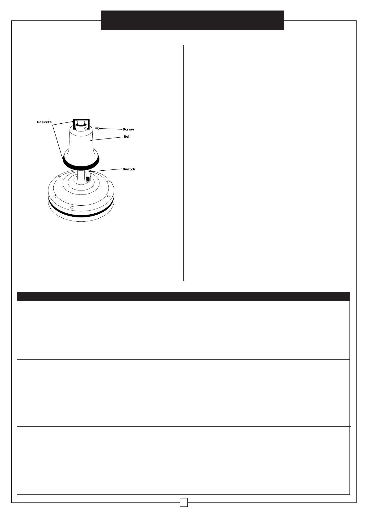
1. Remove screw from bell.
2. Slide rubber gaskets and bell up to reveal
switch.
3. Slide switch to change motor direction.
4. Slide rubber gaskets and bell back down.
5. Align screw hole in bell and rubber gasket
with hole in down rod and reinstall screw.
Reverse Direction
The slide switch has been included, it located on
the couple yoke. Please loosen the set screw on the
top of yoke cover, then slide the bell up to the down
rod, after adjust the slide switch, please repeat the
yoke cover.
NOTE: Turn off and wait for fan to stop before
changing the setting of the forward/reverse slide
switch.
Table of contents
Other Global Fan manuals

Global
Global 248448 User manual

Global
Global 585279 User manual

Global
Global 246340 User manual

Global
Global 293042 User manual

Global
Global FE-60DFOL User manual

Global
Global MH-MF40A User manual

Global
Global 292650 User manual

Global
Global 294498 User manual

Global
Global 292649 User manual

Global
Global 292650 User manual