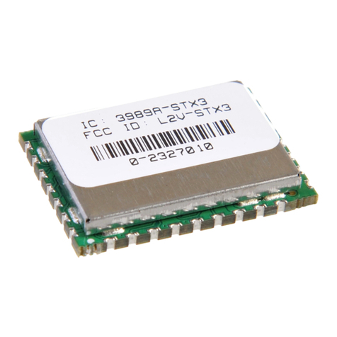
Globalstar ST100 User manual

GLOBALSTAR PROPRIETARY AND CONFIDENTIAL INFORMATION
Use or disclosure of data contained on this sheet is subject to the restrictions in the Distribution Statements on the title page of this
document.
06/18/20 Subject to Change without Notice P a g e | 1

GLOBALSTAR PROPRIETARY AND CONFIDENTIAL INFORMATION
Use or disclosure of data contained on this sheet is subject to the restrictions in the Distribution Statements on the title page of this
document.
06/18/20 Subject to Change without Notice P a g e | 2
Version: 0.8
Date: June 18, 2020
Document number: TBD
Globalstar, Inc.
1351 Holiday Square Blvd.
Covington, LA70433 USA
Copyright © Globalstar Inc., 2020.
All rights reserved. Printed in the United States of America.
Distribution Statements:
GLOBALSTAR CONFIDENTIAL AND PROPRIETARY INFORMATION –All data and information contained in this document
are confidential and proprietary to Globalstar, Inc. and shall be handled in accordance with the Non-Disclosure
Agreement executed between the parties and Globalstar.
WARNING –This document may contain technical data whose export is restricted by the Export Administration Act of
1979, as amended, Title 50, U.S.C., App 2401 et seq. Violations of these export laws are subject to severe criminal
penalties. Disseminate only in accordance with such export laws.
Destruction Notice –Destroy by any method that will prevent disclosure of contents or reconstruction of the document.

GLOBALSTAR PROPRIETARY AND CONFIDENTIAL INFORMATION
Use or disclosure of data contained on this sheet is subject to the restrictions in the Distribution Statements on the title page of this
document.
06/18/20 Subject to Change without Notice P a g e | 3
Table of Contents
Foreward (TBD)....................................................................................................................... Error! Bookmark not defined.
List of Tables (TBD) ................................................................................................................. Error! Bookmark not defined.
List of Figures (TBD)................................................................................................................ Error! Bookmark not defined.
1 Introduction..................................................................................................................................................................8
1.1 Purpose................................................................................................................................................................. 8
1.2 Applicable Documents ..........................................................................................................................................8
1.3 Description............................................................................................................................................................ 8
1.4 Certifications (TBD) ............................................................................................................................................... 9
2 Application.................................................................................................................................................................... 9
2.1 Theory of Operation for Globalstar Simplex ......................................................................................................... 9
2.2 ST100 Functional States (TBD) ............................................................................................................................ 13
2.3 Safety Considerations (TBD).................................................................................... Error! Bookmark not defined.
2.4 Block Diagram ..................................................................................................................................................... 13
2.5 Handling of Electrostatic Sensitive Devices......................................................................................................... 13
2.6 Wiring ................................................................................................................................................................. 14
2.7 Noise Sources...................................................................................................................................................... 14
2.8 Obstructions ....................................................................................................................................................... 14
2.9 PCB Antenna (TBD) ............................................................................................................................................. 14
2.10 External Connections .......................................................................................................................................... 15
2.10.1 External Antenna Option............................................................................................................................. 15
2.10.2 Battery ........................................................................................................................................................ 16
2.10.3 Solar Panel .................................................................................................................................................. 17
2.10.4 14 Pin Connector......................................................................................................................................... 18
2.11 Power Performance Characteristics (TBD) .............................................................. Error! Bookmark not defined.
2.12 Accelerometer (TBD)............................................................................................... Error! Bookmark not defined.
3 General Specifications ................................................................................................................................................ 19
4 Application Programming Interface............................................................................................................................ 20
4.1 ASCII Command List and Format......................................................................................................................... 20
4.1.1 ASCII Format ............................................................................................................................................... 20

GLOBALSTAR PROPRIETARY AND CONFIDENTIAL INFORMATION
Use or disclosure of data contained on this sheet is subject to the restrictions in the Distribution Statements on the title page of this
document.
06/18/20 Subject to Change without Notice P a g e | 4
4.1.1.1 “?”........................................................................................................................................................... 20
4.1.1.2 “esn” ....................................................................................................................................................... 21
4.1.1.3 “data”...................................................................................................................................................... 21
4.1.1.4 “abort” .................................................................................................................................................... 22
4.1.1.5 “bursts”................................................................................................................................................... 22
4.1.1.6 “hardware” .............................................................................................................................................22
4.1.1.7 “firmware” ..............................................................................................................................................22
4.1.1.8 “setup”.................................................................................................................................................... 23
4.1.1.9 “raw”....................................................................................................................................................... 24
4.1.1.10 “bpm”.................................................................................................................................................. 24
4.1.1.11 “auth”.................................................................................................................................................. 25
4.2 Binary Serial Packet Commands.......................................................................................................................... 25
4.2.1 Serial Packet Format ................................................................................................................................... 26
4.2.2 Serial Packet Command List ........................................................................................................................ 26
4.2.2.1 Send Data (0x00)..................................................................................................................................... 26
4.2.2.2 Query Electronic Serial Number (ESN) (0x01) ......................................................................................... 27
4.2.2.3 Abort Transmission (0x03) ...................................................................................................................... 27
4.2.2.4 Query Bursts Remaining (0x04)...............................................................................................................27
4.2.2.5 Query Firmware Version (0x05) ..............................................................................................................29
4.2.2.6 Setup (0x06)............................................................................................................................................ 29
4.2.2.7 Query Setup (0x07) ................................................................................................................................. 30
4.2.2.8 Query Hardware Version (0x09)..............................................................................................................31
4.2.2.9 Set GPS Timeout command..................................................................................................................... 31
4.2.2.10 Get GPS Timeout query....................................................................................................................... 32
4.2.2.11 “SPOT GEN3 emulation. ...................................................................................................................... 33
4.2.2.12 Special consideration for "Byte 7" in the next several commands. ..................................................... 33
4.2.2.13 “Proprietary Track” command ............................................................................................................ 34
4.2.2.14 “Proprietary Motion Activated Track” command................................................................................ 36
4.2.2.15 “Proprietary Motion Activated Dock Mode Track” command............................................................. 38
4.2.2.16 “Update Proprietary Track Data” command ....................................................................................... 39

GLOBALSTAR PROPRIETARY AND CONFIDENTIAL INFORMATION
Use or disclosure of data contained on this sheet is subject to the restrictions in the Distribution Statements on the title page of this
document.
06/18/20 Subject to Change without Notice P a g e | 5
4.2.2.17 “Cancel Proprietary Track/Proprietary Motion Activated Track” command .......................................40
4.2.2.18 “Proprietary Track Status” query ........................................................................................................ 41
4.2.2.19 "Tracking Statistics" query .................................................................................................................. 43
4.2.2.20 "GPS Statistics" query.......................................................................................................................... 45
4.2.2.21 "Transmitter Statistics" query. ............................................................................................................ 47
4.2.2.22 “Send Redundant Burst with GPS” command ..................................................................................... 48
4.2.2.23 “Query Location” command................................................................................................................ 49
4.2.2.24 “Set Lifetime” command ..................................................................................................................... 51
4.2.2.25 “Query Lifetime Status” command...................................................................................................... 53
4.2.2.26 "Set Minimum Track Rate" command ................................................................................................. 54
4.2.2.27 "Query Minimum Track Rate" ............................................................................................................. 55
4.2.2.28 "Suspend/Unsuspend" command ....................................................................................................... 56
4.2.2.29 Suspended State query ....................................................................................................................... 56
4.2.2.30 "Set Low Battery Rate" command....................................................................................................... 57
4.2.2.31 "Query Low Battery Rate" ................................................................................................................... 58
4.2.2.32 “Turn On GPS” command.................................................................................................................... 59
4.2.2.33 “Turn OFF GPS” command .................................................................................................................. 60
4.2.2.34 “Turn On GPS Pass-through” command.............................................................................................. 60
4.2.2.35 “Turn Off GPS Pass-through” command.............................................................................................. 61
4.3 ST100 BOARD Serial Test Command ................................................................................................................... 63
4.3.1 “Self Test” command .................................................................................................................................. 63
4.4 Bootloading. Field update of device firmware .................................................................................................... 64
4.4.1 Nordic nRF52832 firmware update via bootloader (“Buttonless” DFU)...................................................... 64
4.4.2 ON AX50324 firmware update via serial bootloader................................................................................... 64
4.4.2.1 0x60 “Enter Bootloader Command”........................................................................................................ 64
4.4.2.2 0x61 “Flash One Line” ............................................................................................................................. 65
4.4.2.3 0x62 “Enter Application”......................................................................................................................... 69
4.4.2.4 0x63 “Status Query”................................................................................................................................ 70
4.4.3 JTAG programming adaptor. ....................................................................................................................... 71
4.4.4 Nordic low-level load via JTAG .................................................................................................................... 72

GLOBALSTAR PROPRIETARY AND CONFIDENTIAL INFORMATION
Use or disclosure of data contained on this sheet is subject to the restrictions in the Distribution Statements on the title page of this
document.
06/18/20 Subject to Change without Notice P a g e | 6
4.4.5 ON AX50324 low-level load via AXSEM proprietary programming interface. .............................................72
4.5 Example CRC calculation routines for serial packets........................................................................................... 72
4.6 24-bit location format......................................................................................................................................... 75
4.6.1 CALCULATING LATITUDE ............................................................................................................................. 75
4.6.2 CALCULATING LONGITUDE.......................................................................................................................... 75
4.7 Flash Memory Map (TBD) ................................................................................................................................... 76
5 Test Modes ................................................................................................................................................................. 76
5.1 Hardwired Method ............................................................................................................................................. 76
5.2 Soft Command Method....................................................................................................................................... 77
5.2.1 Step 1: Enable the regulatory test modes. .................................................................................................. 77
5.2.2 Step 2: Set the channel that you wish to perform the test on. ................................................................... 78
5.2.3 Step 3: Start the desired mode. .................................................................................................................. 78
5.2.4 Step 4: Disable the test commands.............................................................................................................78
5.2.5 Step 5: Restore the desired setup. .............................................................................................................. 78
6 GENERAL WARNINGS.................................................................................................................................................. 79
7 ANTENNA TUNING GUIDANCE.................................................................................................................................... 80
7.1 Link Budget (TBD).................................................................................................... Error! Bookmark not defined.
7.2 GPS / Satellite Antenna Tuning ........................................................................................................................... 80
7.3 Bluetooth Antenna tuning .................................................................................................................................. 86
8 Globalstar Certification Process for Customer Products............................................................................................. 88
9 REGULATORY APPROVAL ............................................................................................................................................ 88
9.1 Radio Astronomy Site Avoidance ........................................................................................................................ 88
9.2 Regulatory Notices.............................................................................................................................................. 88
10 ACRONYM LIST............................................................................................................ Error! Bookmark not defined.

GLOBALSTAR PROPRIETARY AND CONFIDENTIAL INFORMATION
Use or disclosure of data contained on this sheet is subject to the restrictions in the Distribution Statements on the title page of this
document.
06/18/20 Subject to Change without Notice P a g e | 7
Distribution Statements:
GLOBALSTAR CONFIDENTIAL AND PROPRIETARY INFORMATION –All data and information contained in this document
are confidential and proprietary to Globalstar, Inc.
WARNING –This document may contain technical data whose export is restricted by the Export Administration Act of
1979, as amended, Title 50, U.S.C., App 2401 et seq. Violations of these export laws are subject to severe criminal
penalties. Disseminate only in accordance with such export laws.
Destruction Notice –Destroy by any method that will prevent disclosure of contents or reconstruction of the document.
Globalstar reserves the right to make changes in technical and product specifications without prior notice.
Copyright©2020 Globalstar®Incorporated.
All rights reserved.
Globalstar®is a registered trademark of Globalstar Incorporated.
All other trademarks and registered trademarks are properties of their respective owners.
Printed in the United States of America

GLOBALSTAR PROPRIETARY AND CONFIDENTIAL INFORMATION
Use or disclosure of data contained on this sheet is subject to the restrictions in the Distribution Statements on the title page of this
document.
06/18/20 Subject to Change without Notice P a g e | 8
1Introduction
1.1 Purpose
This document describes the physical, electrical, and functional characteristics of the ST100 satellite transmitter
module with Bluetooth Low Energy. The information contained in this document is intended to provide the
VAR/Integrator with the necessary technical information required to configure and use the module in a custom
application.
This document is intended to be used by engineers and technical management and assumes a general knowledge of
basic engineering practices by the user. Please note that Globalstar is only responsible for ensuring that the ST100
Module meets the published manufacturing specifications described herein.
1.2 Applicable Documents
GS–02-0795 - Simplex Antenna Specification and Test Procedure
GS–07–1247 System Description and Application Note
GS–07–1248 - Remote Telemetry Service Frequency Plan for Simplex Transmitters
Wikipedia article on Intel Hex format: https://en.wikipedia.org/wiki/Intel_HEX
NMEA-0183 rev. 3.0 Specification.
FCC Guidance for use of Radio Modules: KDB996369 D03 and Do4
1.3 Description
The ST100 board is a simplex Satellite transmitter designed to send small packets of user defined data to a network
of low earth orbiting (LEO) satellites using the Globalstar simplex satellite network. The received data is then
forwarded to a user defined network interface that may be in the form of an FTP host or HTTP host where the user
will interpret the data for further processing. The ST100 board must be powered by a battery, or line-powered by a
DC source. The ST100 Board features a solar charging circuit that allows battery charging from an attached solar
panel. The unit will not power from a solar panel alone, without a battery.
The ST100 board contains a satellite transmitter, GPS receiver, motion sensor, Bluetooth Low Energy transceiver,
solar charger, and printed circuit antennas for each of the radio subsystems. The ST100 board has u.FL connectors
on the outputs of the Bluetooth transceiver and GPS receiver / satellite transmitter, which give the user the option
to use external antennas. The ST100 board also has the option for the user to use an external serial port.

GLOBALSTAR PROPRIETARY AND CONFIDENTIAL INFORMATION
Use or disclosure of data contained on this sheet is subject to the restrictions in the Distribution Statements on the title page of this
document.
06/18/20 Subject to Change without Notice P a g e | 9
Under VAR setup and configuration, and normal use by the end user, communication with the device is via a
Bluetooth Low Energy (BLE) GATT/Modem interface with a mixture of ASCII and binary command/query protocols.
The ST100 Board is a small, low-profile device with the dimensions shown below:
Figure 1 Board Physical Dimensions
1.4 Certifications
Bluetooth LE
RoHS
WEEE
2Application
2.1 Theory of Operation for Globalstar Simplex
The ST100 Board operates on the Globalstar LEO satellite network. LEO (Low Earth Orbit) means that there are a
number of satellites in low earth orbit that constantly orbit the planet and can communicate with Globalstar devices
that are within range of its current position.

GLOBALSTAR PROPRIETARY AND CONFIDENTIAL INFORMATION
Use or disclosure of data contained on this sheet is subject to the restrictions in the Distribution Statements on the title page of this
document.
06/18/20 Subject to Change without Notice P a g e | 10
Figure 2 LEO Constellation
Since the satellite position is constantly changing, simplex devices on the ground will transmit (with no knowledge of
any of the satellites locations) and the transmission may be received by one or more satellites. These satellites will then
relay the message to the nearest satellite gateway as shown below. Once received by the satellite gateway, the simplex
message will be delivered to the simplex gateway where redundant messages are discarded and the data from the
message is sent to the OEM via the Internet.
Figure 3 Simplex Messaging
Messages are composed of 1 or more 9-byte payloads. The user application may send a message via the Bluetooth Low
Energy interface to the ST100 board from 1 to 144 bytes in length. The ST100 board will break the message into 9 byte
packets. A 144 byte message would be broken into 16 packets.
INTERNET
T
Satellite Gateways
VAR, VAM
Simplex Transmitter
Simplex Gateway

GLOBALSTAR PROPRIETARY AND CONFIDENTIAL INFORMATION
Use or disclosure of data contained on this sheet is subject to the restrictions in the Distribution Statements on the title page of this
document.
06/18/20 Subject to Change without Notice P a g e | 11
There are brief periods of time where there is no satellite in range of the simplex transmitters due to obstructions
and/or satellite coverage geometry. Since a simplex device has no way of knowing if a transmitted message has been
successfully received, the ST100 Board is designed to send multiple (redundant) transmissions for each message being
sent over the Globalstar network. The default value for the number of redundant transmissions per message is 3. This
means that each message sent to the ST100 Board will normally be transmitted 3 times. Each transmission will contain
the exact same data payload. The redundant transmissions of each message will be sent on a randomized interval with a
configurable maximum and minimum duration. The default configuration is for each re-transmission will occur between
5 to 10 minutes from the previous one with an even pseudo-randomized distribution.
The transmission sequence for a single-packet message using the default setting of 3 redundant transmissions is shown
below.

GLOBALSTAR PROPRIETARY AND CONFIDENTIAL INFORMATION
Use or disclosure of data contained on this sheet is subject to the restrictions in the Distribution Statements on the title page of this
document.
06/18/20 Subject to Change without Notice P a g e | 12
The transmission sequence for a two-packet message using the default setting of 3 redundant transmissions is shown
below.
For normal conditions where the transmitter has an open view of the sky, this will result in a better than 99% chance
that the message will be received.

GLOBALSTAR PROPRIETARY AND CONFIDENTIAL INFORMATION
Use or disclosure of data contained on this sheet is subject to the restrictions in the Distribution Statements on the title page of this
document.
06/18/20 Subject to Change without Notice P a g e | 13
2.2 Block Diagram
2.3 Handling of Electrostatic Sensitive Devices
Some components on the ST100 PCB are sensitive to electrostatic discharge (ESD). The following general guidelines can
help reduce damage due to ESD.
1. Use a grounding bracelet if possible, to minimize charge build-up on personnel.
2. Handle the ST100 PCB by the long edges without touching components or printed circuit paths. The long edges
measure approximately 2" (50.8mm). The short edges measure approximately 1" (25.4mm). Note: There are ESD
sensitive devices located closer to the short edges than the long edges.
3. Store the ST100 PCB in static sensitive packaging whenever possible.

GLOBALSTAR PROPRIETARY AND CONFIDENTIAL INFORMATION
Use or disclosure of data contained on this sheet is subject to the restrictions in the Distribution Statements on the title page of this
document.
06/18/20 Subject to Change without Notice P a g e | 14
2.4 Wiring
If the ST100 will be line-powered, proper installation and field wiring practices are important to follow. Users and
installers should familiarize themselves with the requirements of all applicable codes, laws, and standards.
2.5 Noise Sources
Electrical noise is an important consideration in any installation of the ST100. When possible, sufficient physical
separation should be maintained between electrical noise sources and the ST100.
2.6 Obstructions
If the internal ST100 Bluetooth and/or GPS/Satellite antennas are used, care should be taken as to what is placed above,
below, and around the short edges of the PCB. The short edges are where the ST100 internal antennas are located. For
best performance, the ST100 should have an unobstructed view of the sky, either outdoors or in a glass-enclosed area
such as a vehicle dashboard.
2.7 PCB Antenna
The ST100 has 2 PCB Trace antennas on the board for Satellite and Bluetooth transmissions. These are the default
antennas for the ST100.
Regulatory Note: The ST100 was certified using its Satellite and Bluetooth PCB Trace antennas. The use of any external
antennas will require additional regulatory testing plus approval from Globalstar Engineering.

GLOBALSTAR PROPRIETARY AND CONFIDENTIAL INFORMATION
Use or disclosure of data contained on this sheet is subject to the restrictions in the Distribution Statements on the title page of this
document.
06/18/20 Subject to Change without Notice P a g e | 15
2.8 External Connections
The picture (below) depicts the PCB external interfaces.
2.8.1 External Antenna Option
The ST100 has provisions where an external antenna can be used on either the Bluetooth and/or the GPS /
Satellite antennas. If an external antenna is used, care should be taken when connecting the external antenna
to the u.FL connector - Hirose part # U.FL-R-SMT(10) on the ST100 PCB. If this option is desired, Globalstar
needs to know before boards are ordered.
Solar (+) terminal
Solar (-) terminal
Battery (+) terminal
Battery (-) terminal
14 pin connector
GPS/Satellite u.FL connector

GLOBALSTAR PROPRIETARY AND CONFIDENTIAL INFORMATION
Use or disclosure of data contained on this sheet is subject to the restrictions in the Distribution Statements on the title page of this
document.
06/18/20 Subject to Change without Notice P a g e | 16
Regulatory Note: The ST100 was certified using its Satellite and Bluetooth PCB Trace antennas. The use of any external
antennas will require additional regulatory testing plus approval from Globalstar Engineering.
2.8.2 Battery
The ST100 has terminals on the PCB where a battery can be soldered to. The user / installer should carefully
note the location of the positive and negative terminals marked on the PCB and solder the battery accordingly.
It will be up to the user / installer to verify the power requirements as mentioned in Section 3 “General
Specifications”: Table 4: Power Requirements. Note: RoHS-compliant and lead-free solder must be used in
order to maintain the RoHS-compliance of the ST100.
The ST100 can be powered in the following configurations:
1. Connecting a 3.4V to 5.5VDC source to the battery terminals. The source must meet the
requirements mentioned in Table 4.
2. Connecting a battery to the battery terminals and connecting a 0.75V to 5VDC source to the solar
terminals. The source on the solar terminals must meet the requirements mentioned in Table 4.
Table 1 –Nominal Battery Characteristics
Manufacturer /
Part #
Description
Protection
circuit included
IEC62133
approvals
Dimensions
Notes
PK Cell part #
LP503035
3.7V,
500mAh,
Li-Polymer
Yes
Yes
35 x 30 x 5mm
+/- 0.1mm
Battery is normally stocked
with a connector attached,
but can be ordered
without connector
PK Cell part #
LP552535
3.7V,
420mAh,
Li-Polymer
Yes
No
35 x 25 x
3.5mm
+/- 0.1mm
Battery is normally stocked
with a connector attached,
but can be ordered
without connector
Data Power
Technology
Limited part #
DTP401525
3.7V,
110mAh,
Li-Polymer
Yes
No
25 x 15 x 4mm
+/- 0.1mm
Battery will only work
down to 0°C
Notes:
1. This list is not a complete list of acceptable batteries. These are batteries that Globalstar has identified and
tested as acceptable.
2. The VAR/installer should review the pairing of solar panel / battery and determine if the solar panel is

GLOBALSTAR PROPRIETARY AND CONFIDENTIAL INFORMATION
Use or disclosure of data contained on this sheet is subject to the restrictions in the Distribution Statements on the title page of this
document.
06/18/20 Subject to Change without Notice P a g e | 17
adequate for use with the selected battery.
3. Regulatory Note: If a battery is used, it will be the responsibility of the VAR/installer to obtain / verify the
relevant battery approvals / certifications for where the end-product will be used (i.e. IEC62133 approval)
4. Due to the solar charger chip’s 100mA max input current, the max recommended battery size is 500mAh.
2.8.3 Solar Panel
The ST100 has terminals on the PCB where a solar panel can be soldered to. The user / installer should carefully note the
location of the positive and negative terminals marked on the PCB and solder the solder panel accordingly. It will be up
to the user / installer to verify the solar power requirements as mentioned in Section 3 “General Specifications”: Table 4:
Power Requirements. Note: RoHS-compliant and lead-free solder must be used in order to maintain the RoHS-
compliance of the ST100
Table 2 –Nominal Solar Panel Characteristics
Manufacturer
/ Part #
Description
Voc
(open-
circuit
voltage)
Vmpp
(max
power
point)
Isc
(short-
circuit
current)
Typical Full-Sun Current
available for charging
the battery (Note 3)
Dimensions
PowerFilm
part # 2.4V
94x73mm
BSC
2-cell,
2.4V,
288mW
3.6V
2.4V
140mA
50-60 mA
94 x 73 x
0.8mm
PowerFilm
part # SP2.4-
37
4-cell,
2.4V,
54mW
3.6V
2.4V
30mA
7-11 mA
50 x 36.5 x
0.8mm
PowerFilm
part # SP2.4-
37
5-cell,
2.4V,
67.5mW
4.5V
3V
30mA
10-14 mA
60 x 36.5 x
0.8mm
IXYS part #
SM111K06L
High
Efficiency,
3.35V,
156mW
4.15V
3.35V
46.7mA
20-30mA
42 x 21 x 2 mm
Notes:
1. This list is not a complete list of acceptable solar panels. These are panels that Globalstar has identified and

GLOBALSTAR PROPRIETARY AND CONFIDENTIAL INFORMATION
Use or disclosure of data contained on this sheet is subject to the restrictions in the Distribution Statements on the title page of this
document.
06/18/20 Subject to Change without Notice P a g e | 18
tested as acceptable.
2. The VAR/installer should review the pairing of solar panel / battery and determine if the solar panel is
adequate for use with the selected battery.
3. This value is based on the efficiency of the solar charger chip, which is typically 80-85%.
4. The solar panel should be chosen for outdoor use, if the end-application will be mostly outdoors.
2.8.4 14 Pin Connector
Table 3 –14 pin Connector (Molex 5034801400)
Pin #
Signal Name
Description
Notes
1
3V0
3V supply
The 3V supply is only meant to
power loads less than 20mA
2
SWDIO
Bluetooth processor programming line
3
GND
PCB Ground
4
SWDCLK
Bluetooth processor programming line
5
GND
PCB Ground
6
SAT_DBG_DATA
ASIC programming line
7
SAT_DBG_CLK
ASIC programming line
8
SAT_DBG_EN
ASIC programming line
9
SAT_RST_N
ASIC reset
10
EXT_TX_CONN
External Serial Port Transmit
This is the Receive signal on the
Bluetooth processor.
11
EXT_RTS_CONN
External Serial Port Request to Send
This is a GPIO signal connected
to the Bluetooth processor
12
MCU/BLE_#RESET
Bluetooth processor reset
13
EXT_CTS_CONN
External Serial Port Clear to Send
This is a GPIO signal connected
to the Bluetooth processor
14
EXT_RX_CONN
External Serial Port Receive
This is the Transmit signal on the
Bluetooth processor.
Notes
1. The mating cable for Molex 5034801400 is Molex part # 0152660153, or equivalent.

GLOBALSTAR PROPRIETARY AND CONFIDENTIAL INFORMATION
Use or disclosure of data contained on this sheet is subject to the restrictions in the Distribution Statements on the title page of this
document.
06/18/20 Subject to Change without Notice P a g e | 19
3General Specifications
Table 4 –Operating Conditions
Component Temperature Range (without battery)
-30 to +70°C (Note 1)
Board Functional Temperature Range
-20 to +60°C
Board Storage Temperature Range (without battery)
-40 to +85°C
Power requirements (Battery Input)
3.4V to 5.5VDC (Notes 2, 3, 4)
Standby current: 30-40uA
Input protection (Battery Input)
PTC resettable fuse
Hold current
-30C: 1.5Amps, 20C: 1.1Amps, 70C: 0.65Amps
Power requirements (Solar Input)
0.75V to 5VDC (Notes 5, 6, 7)
Minimum power required: 50mW
Maximum power: 510mW
External Serial Port Parameters
3V (Note 8)
Current Drain
Satellite RF output
24.5dBm (Note 9)
Frequency configurable to 1611.25MHz,
1616.25MHz, or 1618.75MHz
GPS / Satellite antenna gain
+1.06 dBi
Bluetooth Low Energy (BLE)
0dBm TX power
-69dBm RX sensitivity
Bluetooth antenna gain
-1.09 dBi
Notes:
1. The -30 to +70°C temperature range is for the ST100 components and doesn’t include the battery or solar
panel.
2. The power source on the battery input should be able to supply 500mA pulse current (at 3.7V) for 1.5
seconds. If the end-application expects to have 16 packet messages, the supply should be able to provide this
pulse current up to 16 times in succession.
3. If a battery is used, the VAR/installer should verify the battery’s performance at the application’s lowest
expected ambient temperature before proceeding with the selected battery.
4. The ST100 has the option to install a battery protection circuit. The VAR/installer will need to inform
Globalstar before ordering PCBs if this feature is desired.
5. Both the 0.75V and 50mW requirements must be met on the solar input for charging a depleted battery.

GLOBALSTAR PROPRIETARY AND CONFIDENTIAL INFORMATION
Use or disclosure of data contained on this sheet is subject to the restrictions in the Distribution Statements on the title page of this
document.
06/18/20 Subject to Change without Notice P a g e | 20
6. The maximum current the solar charger chip on the ST100 board will accept is about 100mA, regardless of
solar panel size.
7. If connecting a 5V source to the solar input, the source must be current limited to 100mA.
8. The external serial port consists of 4 GPIO pins connected to the ST100 Bluetooth processor.
9. The 24.5dBm is the conducted power going into the antenna.
4Application Programming Interface
The ST100 Board provides a Bluetooth Low Energy (BLE) GATT/Modem interface for controlling the operation of the
device. Commands are used to send information over the simplex network, operate the GPS engine, and monitor the
internal operation of the device. The following types of commands are provided by the ST100 Interface:
•Simple ASCII Text commands for basic operation.
•Legacy binary commands, primarily emulating the interface of the STINGR product
4.1 ASCII Command List and Format
The ST100 Board accepts a set of ASCII commands to query the board for status, and to cause it to perform various
commands.
Commands take the form of a “keyword” and a variable number of arguments, in the same form of command line
arguments in a Windows or Linux command prompt window.
4.1.1 ASCII Format
Command <arg1> <arg2> <arg3> … <argn> <CR>
Where the “CR” is an Ascii Carriage Return or Enter (Decimal value of 13).
4.1.1.1 “?”
Print a list of commands.
Command: ?
Arguments: None
Example: ?
Example response:
Commands List:
esn
data
Other manuals for ST100
2
Table of contents
Other Globalstar Control Unit manuals
Popular Control Unit manuals by other brands

Texas Instruments
Texas Instruments Piccolo F280049C user guide

WAREMA
WAREMA WMS WebControl pro manual

Atkinson Electronics
Atkinson Electronics GSCM-MINI-D quick guide

Siemens
Siemens Flowrite 599 Series Technical instructions

Digi
Digi XBee3 DigiMesh 2.4 Update instruction manual

Burkert
Burkert 2300 Series quick start

Arkel
Arkel ARCODE 4B26A Hardware manual

Hubbel
Hubbel CIRCUIT GUARD GFM20 Installation and operating instructions

Lennox
Lennox iHarmony 10C16 Installation and setup guide

Lucent Technologies
Lucent Technologies PacketStar PSAX 1000 user guide

Fibocom
Fibocom G600 AT Command User Manual

Ahlborn
Ahlborn ALMEMO 809 operating instructions