manuals.online logo
Brands
  1. Home
  2. •
  3. Brands
  4. •
  5. Emerson
  6. •
  7. Control Unit
  8. •
  9. Emerson YARWAY B Manual

Emerson YARWAY B Manual

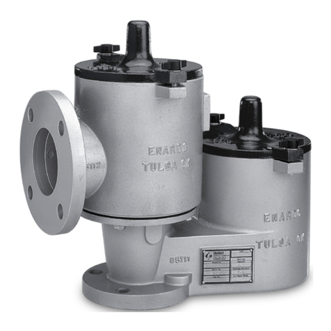
YARWAY SEATLESS BLOW-OFF VALVES
Type b and Type c
Installation, operation and maintenance instructions
PRINCIPLE OF OPERATION
The seatles blow-off valve is a manually
operated sliding primarily for boiler blow-off
service where high temperature fluid,
containing dirt, sediment and scale, is
encountered.
When the valve is open (Fig. 2) the controlled
fluid passes through the ports in the plunger
(8) and lower gland (5) and discharges to the
valve outlet via the center of the plunger
assembly. In the closed position the shoulder
of the plunger assembly contacts the upper
gland (6). This feature provides additional
loading from the handwheel to compress the
packing rings (3) (4) and assure leak-tight
shut-off. Any packing relaxation during service
is accommodated by the heavy compression
springs (14) which provide a constant packing
load.
© 2018 Emerson. All Rights Reserved.Emerson.com/FinalControl VCIOM-03114 EN 18/10
VALVE OPERATION
Open the valve quickly and fully. Never use this
valve to throttle the flow in the partly open
condition as this will reduce the packing life.
Close the valve in the same manner. Apply a
hard turn at the end of the valve travel. This
will assure that the plunger seats against the
upper gland which, in turn, will recompress
the packing rings.
In operating Yarway seatless valves in tandem,
the valve next to the boiler should be used as
the blowing valve, opened last and closed first.
The outside or sealing valve should be opened
first and closed last.
If a Yarway double tghtening valve is used in
tandem with a Yarway seatless valve, the
double tighteningvalve is placed next to the
boiler and is opened first and closed last. The
Seatless or outside valve is the blowing valve
and is opened last and closed first.
WARNING
Hot discharge from this product may cause severe
burns. Discharge must be piped away or directed
so that persons in the vicinity are not endangered.
This product must be isolated, vented and cool to
the touch before repairing or inspecting.
2
9A
12
11
2
9
6
4
5
10,10A
3
8
1
2A
15
15A
14
YARWAY SEATLESS BLOW-OFF VALVES
Type b and Type c
MAINTENANCE AND ADJUSTMENT
Packing ring adjusment
Yoke nuts (15A) should be tightened at regular
intervals. The yoke springs (14) will maintain a
constant load on the packing. Packing rings
will relax slightly during use and an adjustment
may be required. To adjust the packing,
back the plunger off slightly by turning the
handwheel (do not allow flow to occur) and then
tighten the yoke nuts. Approximately ¼ to ½
turn should be sufficient. Reseat the plunger
against the upper gland.
NOTE:
If the valve has not been operated for a long period, the
packing nuts should be adjusted prior to blowing down
the boiler.
Lubrication
A fitting (2A) is provided on the yoke for
lubricating the ball thrust bearing (11) and the
stem collar. This fitting is compatible with an
Alemite No. 7585 gun. A high temperature
grease equivalent to Texaco Regal AFB2
should be used to lubricate this area. Stem
threads should be kept well lubricated. A good
grade of antiseize compound similar to Never-
Seez NS165 should be used. Both of these
areas should be lubricated every six months.
Installation of packing rings
WARNING
This procedure should not be attempted unless all
pressure has been vented from the valve, and its
connecting lines, and the temperature of the valve
is at or near ambient.
Remove the stopscrew (10) then remove the
yoke nuts and springs. Turn the handwheel to
open the valve. This will raise the plunger. Turn
the handwheel to close the valve. This will raise
the yoke. Turn the yoke so that the holes and
studs are out of line and turn the handwheel to
open the valve. The plunger is thus withdrawn
from the valve.
Next, remove the glands and the old packing.
This can be done by using a Yarway gland and
packing puller or similar tool (Fig. 3) in the
following manner: Insert the tool until the
pawls engage the ports in the lower gland.
Tighten the nut on the top of the puller to draw
out the lower gland, upper packing and upper
gland. The lower packing can then be removed
using a hook tool. Care should be exercised,
however, so that the lower packing groove is
not damaged. Install new packing rings, (Fig. 4
or 5) glands and stopscrew in the body and
replace the yoke, with the plunger screwed all
the way up on the stem, in place and using the
yoke nuts pull down the yoke assembly. Next,
place the springs under the nuts and adjust as
previously described.
TYPE C ANGLE VALVE
Item Description
FIGURE 2
Type C angle valve
NOTE:
When ordering parts, use parts numbers and names
shown in table, specify size and type of valve, figure
number and operating pressure (see nameplate on
valve). Maintenance kits for Type B valves include
the following: cast iron valve, 250 psi: upper & lower
glands, packing set, springs, studs, nuts, stop screw,
stop screw gasket, cast steel valve, 300 psi & 400
psi: upper and lower glands, packing set, stem, ball
bearing, springs, studs, nuts, stop screw gasket.
1Body
2Yoke
2A Lubrication fitting
3Lower packing ring assembly
4Upper packing ring assembly
5Lower gland
6Upper gland
8Plunger assembly
9Stem
9A Stem nut
10 Stop screw
10A Stop screw gasket
11 Rail thrust bearing (2 Type C; 1 Type B)
12 Handwheel
13 Extension lever (Type C only)
14 Yoke springs (4 per set)
15 Yoke studs (4 per set)
15A Yoke stud nuts (4 per set)
3


 



 

RIGHT TO KNOW LAWS AND OSHA STANDARD
29CFR (1910.1200)
Material Safety Data Sheets on the following
Yarway products: Valves, Steam Traps and
Strainers
The OSHA Hazard Communication Standard
29CFR 1910.1200, states that the standard does
not apply to “articles.” The standard defines an
article as:
“A manufactured item formed to a specific
shape or design for a particular use which does
not release or otherwise expose an employee to
a hazardous chemical under normal conditions
of use.”
The above named products fall within the
definition of an “article”, no Material Safety
Data Sheets are available or are required. Our
product is manufactured as an “end product.”
If the product is a weld end the following
applies.
YARWAY SEATLESS BLOW-OFF VALVES
Type b and Type c
NOTE:
Any malfunction of this product must be reported to
the service department. Repair made to the product by
unauthorized personnel will void the warranty.
WARNING
Materials used in manufacture of Yarway
products are considered in a stable condition
when shipped. However, under certain conditions
purchasers could create potential hazardous
conditions by their future operations.
CAUTION
Welding, cutting, burning, machining or grinding
of this product can generate toxic dust and fumes
of potentially hazardous ingredients. The dust
or fumes can cause irritation of the respiratory
tract, nose, throat, skin and eyes. It may cause
temporary or permanent respiratory disease in
a small percentage of exposed individuals. Use
moderate ventilation when grinding or welding.
Avoid breathing dust, fumes or mist. Avoid
prolonged skin contact with dust or mist. Maintain
dust levels below OSHA and ACGIH levels. Use
protective devices. Wash hands thoroughly after
contact with dust before eating or smoking.
FIGURE 4
Without support ring
FIGURE 5
With support ring
FIGURE 3
Seatless blow-off valve gland and packing
assembly
PARTS LIST
Item Description
GLAND AND PACKING PULLER
Item Description
1Bridge plate assembly
2Jack screw
3Spring
4Thrust washer
5Nut 1¼” hex
6Screw (spring mtg.)
946458 Packing puller w/box*
946459-01 1”, 1¼” Head assembly
946459-02 1½” Head assembly
946459-03 2” Head assembly
946459-04 2½” Head assembly
Upper gland
Upper packing
backup ring
Upper packing ring
Valve inlet
Plunger
Lower gland
Support ring
Lower packing ring
Upper gland
Upper packing
backup ring
Upper packing ring
Valve inlet
Plunger
Lower gland
Lower packing ring
Valve body
Upper gland
Lower gland
Upper packing
Lower packing
Note: chisel
marks on head
give indication
of direction of
pawls when
inside valve body
Edge of hole peened
to hold pin in place
Head assembly interchange head assembly available
for either 1”, 1¼”, 1½”, 2” or 2½”valves. order size or
sizes required.
Head assembly fits all types of Yarway seatless
valves in size specified
Neither Emerson, Emerson Automation Solutions, nor any of their affiliated entities assumes responsibility for the selection, use or maintenance of any product.
Responsibility for proper selection, use, and maintenance of any product remains solely with the purchaser and end user.
Yarway is a mark owned by one of the companies in the Emerson Automation Solutions business unit of Emerson Electric Co. Emerson Automation Solutions, Emerson
and the Emerson logo are trademarks and service marks of Emerson Electric Co. All other marks are the property of their respective owners.
The contents of this publication are presented for informational purposes only, and while every effort has been made to ensure their accuracy, they are not to be
construed as warranties or guarantees, express or implied, regarding the products or services described herein or their use or applicability. All sales are governed by
our terms and conditions, which are available upon request. We reserve the right to modify or improve the designs or specifications of such products at any time without
notice.
Emerson.com/FinalControl

This manual suits for next models

1

Other Emerson Control Unit manuals

Emerson Fisher 98LD User manual

Emerson

Emerson Fisher 98LD User manual
Emerson CV4-7 Series User manual

Emerson

Emerson CV4-7 Series User manual

Emerson Neotecha Sapro Quick guide

Emerson

Emerson Neotecha Sapro Quick guide

Emerson KEYSTONE DUBEX User manual

Emerson

Emerson KEYSTONE DUBEX User manual

Emerson KTM RICHARDS FIGURE R382 User manual

Emerson

Emerson KTM RICHARDS FIGURE R382 User manual

Emerson Tartarini V Series User manual

Emerson

Emerson Tartarini V Series User manual

Emerson KGA User manual

Emerson

Emerson KGA User manual

Emerson Sempell series User manual

Emerson

Emerson Sempell series User manual

Emerson Dixell XEC Supercap Wiring diagram

Emerson

Emerson Dixell XEC Supercap Wiring diagram

Emerson Dixell XEV20D User manual

Emerson

Emerson Dixell XEV20D User manual

Emerson Fisher Large ED User manual

Emerson

Emerson Fisher Large ED User manual

Emerson Fisher Multiport Flow Selector User manual

Emerson

Emerson Fisher Multiport Flow Selector User manual

Emerson Keystone OM3 - EPI2 User manual

Emerson

Emerson Keystone OM3 - EPI2 User manual

Emerson Fisher Type 289P User manual

Emerson

Emerson Fisher Type 289P User manual

Emerson SW95 User manual

Emerson

Emerson SW95 User manual

Emerson Liebert iCOM User manual

Emerson

Emerson Liebert iCOM User manual

Emerson Daniel 770 User manual

Emerson

Emerson Daniel 770 User manual

Emerson Fisher VS100 Series User manual

Emerson

Emerson Fisher VS100 Series User manual

Emerson 581 Series Installation instructions

Emerson

Emerson 581 Series Installation instructions

Emerson Asco Bio-Pure User manual

Emerson

Emerson Asco Bio-Pure User manual

Emerson 1805 Series User manual

Emerson

Emerson 1805 Series User manual

Emerson Fisher GX User manual

Emerson

Emerson Fisher GX User manual

Emerson Fisher ET User manual

Emerson

Emerson Fisher ET User manual

Emerson Fisher 122A Series User manual

Emerson

Emerson Fisher 122A Series User manual

Popular Control Unit manuals by other brands

Nice A3 instruction manual

Nice

Nice A3 instruction manual

ExTox ET-1D Series instruction manual

ExTox

ExTox ET-1D Series instruction manual

Tuxhorn tubra-eTherm manual

Tuxhorn

Tuxhorn tubra-eTherm manual

Zurn Wilkins 375 Installation, Testing, Maintenance Instructions

Zurn Wilkins

Zurn Wilkins 375 Installation, Testing, Maintenance Instructions

Honeywell ADEMCO 4100SM Installation and setup guide

Honeywell

Honeywell ADEMCO 4100SM Installation and setup guide

Copley Controls Accelnet Plus AEV-090-14 user guide

Copley Controls

Copley Controls Accelnet Plus AEV-090-14 user guide

Danfoss EVR 2 installation guide

Danfoss

Danfoss EVR 2 installation guide

GEA DHV DN65/50 KVS 16 operating instructions

GEA

GEA DHV DN65/50 KVS 16 operating instructions

Nibe VVM 500 user manual

Nibe

Nibe VVM 500 user manual

Lutron Electronics QSN-2DALUNV-S install guide

Lutron Electronics

Lutron Electronics QSN-2DALUNV-S install guide

Easy ELC12 Series user manual

Easy

Easy ELC12 Series user manual

Eaton Cutler-Hammer IQMSSPM instructions

Eaton

Eaton Cutler-Hammer IQMSSPM instructions

ABB Busch-priOn Series Technical reference manual

ABB

ABB Busch-priOn Series Technical reference manual

Honeywell VR8215S installation instructions

Honeywell

Honeywell VR8215S installation instructions

Telit Wireless Solutions BlueMod+S50/AI Hardware user's guide

Telit Wireless Solutions

Telit Wireless Solutions BlueMod+S50/AI Hardware user's guide

Yamaha disklavier DKC-850 quick start guide

Yamaha

Yamaha disklavier DKC-850 quick start guide

Gira 1283 00 Mounting instructions

Gira

Gira 1283 00 Mounting instructions

BEAMEX POC4 instruction manual

BEAMEX

BEAMEX POC4 instruction manual

manuals.online logo
manuals.online logoBrands
  • About & Mission
  • Contact us
  • Privacy Policy
  • Terms and Conditions

Copyright 2025 Manuals.Online. All Rights Reserved.