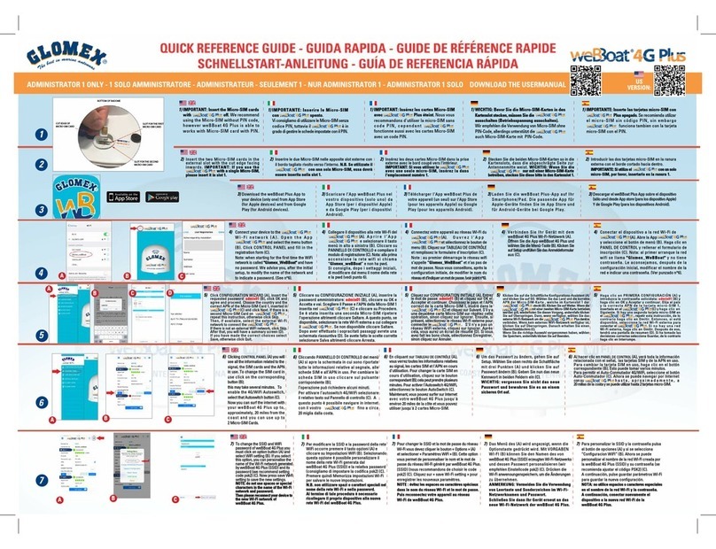
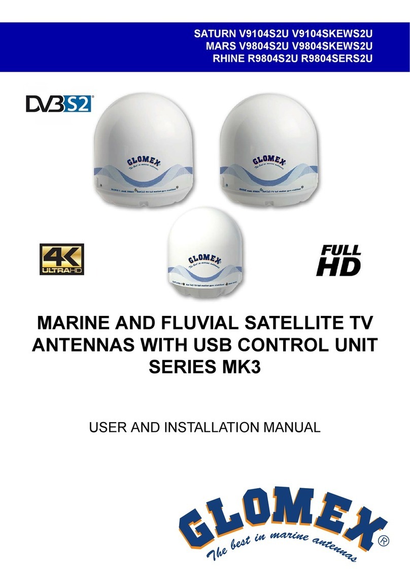
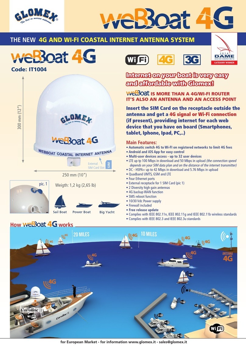
Glomex NEO Pandora User manual

“NEO” TV SATELLITE ANTENNAS
“NEO” PANDORA -
39cm dish RHEA / SATURN - 47cm dish
dCSS
MARINE 4K FULL HD DVB-S2 AND
dCSS/SCR TV SATELLITE ANTENNAS
WITH WIRELESS CONTROL VIA APP
MARS / RHINE - 60cm dish
Bluetooth

“NEO” TV SATELLITE ANTENNAS
60
ENGLISH
www.glomex.it

“NEO” TV SATELLITE ANTENNAS
61
www.glomex.it
ENGLISH
INDEX
1. FOREWORD . . . . . . . . . . . . . . . . . . . . . . . . . . . . . . . . . . . . . . . . . . . . . . . . . . . . . . . . . . . . . . . . . . . . . . . . . . 63
1.1 DELIVERY LETTER. . . . . . . . . . . . . . . . . . . . . . . . . . . . . . . . . . . . . . . . . . . . . . . . . . . . . . . . . . . . . . . . . . 63
1.2 ANTENNA IDENTIFICATION . . . . . . . . . . . . . . . . . . . . . . . . . . . . . . . . . . . . . . . . . . . . . . . . . . . . . . . . 63
1.3 WARRANTY . . . . . . . . . . . . . . . . . . . . . . . . . . . . . . . . . . . . . . . . . . . . . . . . . . . . . . . . . . . . . . . . . . . . . . . . 63
1.4 GENERAL SAFETY RULES . . . . . . . . . . . . . . . . . . . . . . . . . . . . . . . . . . . . . . . . . . . . . . . . . . . . . . . . . . 64
1.5 ENVIRONMENT. . . . . . . . . . . . . . . . . . . . . . . . . . . . . . . . . . . . . . . . . . . . . . . . . . . . . . . . . . . . . . . . . . . . . 64
2. PRODUCT DESCRIPTION . . . . . . . . . . . . . . . . . . . . . . . . . . . . . . . . . . . . . . . . . . . . . . . . . . . . . . . . . . . . . 65
3. CONTENTS AND CONNECTIONS. . . . . . . . . . . . . . . . . . . . . . . . . . . . . . . . . . . . . . . . . . . . . . . . . . . . . 67
4. NECESSARY TOOLS FOR ASSEMBLY (NOT PROVIDED) . . . . . . . . . . . . . . . . . . . . . . . . . . . . . . 71
5. INSTALLATION . . . . . . . . . . . . . . . . . . . . . . . . . . . . . . . . . . . . . . . . . . . . . . . . . . . . . . . . . . . . . . . . . . . . . . . 72
6. ASSEMBLY . . . . . . . . . . . . . . . . . . . . . . . . . . . . . . . . . . . . . . . . . . . . . . . . . . . . . . . . . . . . . . . . . . . . . . . . . . . 74
6.1 “NEO” PANDORA, “NEO” RHEA AND “NEO” DCSS SATURN 4 . . . . . . . . . . . . . . . . . . . . . . . 74
6.2 “NEO” SATURN 4 , “NEO” MARS AND “NEO” RHINE ANTENNAS . . . . . . . . . . . . . . . . . . . . 78
6.3 LOWER RADOME CUTTING TEMPLATE . . . . . . . . . . . . . . . . . . . . . . . . . . . . . . . . . . . . . . . . . . . . 85
6.4 CUTTING TEMPLATE FOR BUILT-IN INSTALLATION OF THE CONTROL UNIT . . . . . 86
6.5 SKEW CALIBRATION (MANUAL). . . . . . . . . . . . . . . . . . . . . . . . . . . . . . . . . . . . . . . . . . . . . . . . . . . . 87
6.6 AUTOMATIC SKEW CALIBRATION . . . . . . . . . . . . . . . . . . . . . . . . . . . . . . . . . . . . . . . . . . . . . . . . . 87
6.7 SKEW ADJUSTMENT GRID FOR EUROPE . . . . . . . . . . . . . . . . . . . . . . . . . . . . . . . . . . . . . . . . . . 88
7. TURNING ON AND SELECTING THE SATELLITE - MANUAL PROCEDURE. . . . . . . . . . . . 90
8. USING GLOMEX SATELLITE APP . . . . . . . . . . . . . . . . . . . . . . . . . . . . . . . . . . . . . . . . . . . . . . . . . . . . . 92
8.1 FIRST CONFIGURATION - STARTING UP THE CONTROL UNIT . . . . . . . . . . . . . . . . . . . . . 92
8.2 CONNECTION BETWEEN APP AND CONTROL UNIT. . . . . . . . . . . . . . . . . . . . . . . . . . . . . . . 92
8.3 CONTROL PANEL . . . . . . . . . . . . . . . . . . . . . . . . . . . . . . . . . . . . . . . . . . . . . . . . . . . . . . . . . . . . . . . . . . 94
8.4 SATELLITE DATABASE . . . . . . . . . . . . . . . . . . . . . . . . . . . . . . . . . . . . . . . . . . . . . . . . . . . . . . . . . . . . . 94
8.5 UPDATING THE FREQUENCIES AND SATELLITE DATABASE. . . . . . . . . . . . . . . . . . . . . . . 95
9. APP ADVANCED MODE FOR INSTALLATION OPERATORS - ANTENNA
CALIBRATION AND UPDATES . . . . . . . . . . . . . . . . . . . . . . . . . . . . . . . . . . . . . . . . . . . . . . . . . . . . . . . . 96
9.1 ANTENNA REGISTRATION . . . . . . . . . . . . . . . . . . . . . . . . . . . . . . . . . . . . . . . . . . . . . . . . . . . . . . . . . 96
9.2 UPDATING THE CONTROL UNIT SOFTWARE . . . . . . . . . . . . . . . . . . . . . . . . . . . . . . . . . . . . . . 97
9.3 UPDATING THE BOARD ANTENNA SOFTWARE. . . . . . . . . . . . . . . . . . . . . . . . . . . . . . . . . . . . 98
9.4 SETTING THE PARAMETERS OF A SATELLITE MANUALLY . . . . . . . . . . . . . . . . . . . . . . . . 99
9.5 LOG VISUALIZATION . . . . . . . . . . . . . . . . . . . . . . . . . . . . . . . . . . . . . . . . . . . . . . . . . . . . . . . . . . . . . . 100
10. UPDATING THE SATELLITE FREQUENCES USING THE SD CARD . . . . . . . . . . . . . . . . . . . 101
11. UPDATING THE CONTROL UNIT SOFTWARE USING THE SD CARD. . . . . . . . . . . . . . . . . 103
12. UPDATING THE BOARD ANTENNA USING THE SD CARD . . . . . . . . . . . . . . . . . . . . . . . . . . . 105
13. TIPS FOR CORRECT USAGE . . . . . . . . . . . . . . . . . . . . . . . . . . . . . . . . . . . . . . . . . . . . . . . . . . . . . . . . . 107
13.1 FOOTPRINTS: SATELLITE TRANSMISSION AREAS . . . . . . . . . . . . . . . . . . . . . . . . . . . . . . . . 108
14. REPLACING THE POWER SUPPLY PROTECTION FUSE. . . . . . . . . . . . . . . . . . . . . . . . . . . . . . 110

“NEO” TV SATELLITE ANTENNAS
62 www.glomex.it
ENGLISH
15. TROUBLESHOOTING . . . . . . . . . . . . . . . . . . . . . . . . . . . . . . . . . . . . . . . . . . . . . . . . . . . . . . . . . . . . . . . . 111
16. RESHIPPING . . . . . . . . . . . . . . . . . . . . . . . . . . . . . . . . . . . . . . . . . . . . . . . . . . . . . . . . . . . . . . . . . . . . . . . . . 114
17. TECHNICAL SPECIFICATIONS . . . . . . . . . . . . . . . . . . . . . . . . . . . . . . . . . . . . . . . . . . . . . . . . . . . . . . . 115
18. TECHNICAL SUPPORT. . . . . . . . . . . . . . . . . . . . . . . . . . . . . . . . . . . . . . . . . . . . . . . . . . . . . . . . . . . . . . . 116

“NEO” TV SATELLITE ANTENNAS
63
www.glomex.it
ENGLISH
1. FOREWORD
1.1 DELIVERY LETTER
Welcome: with the installation of this antenna,
the world of satellite television comes on board
your boat.
This manual has been drafted in order to help
you with the correct installation and operation of
the antenna.
1.2 ANTENNA IDENTIFICATION
When calling GLOMEX or an authorized Service
Centre, always provide the serial number and
the model of the antenna, shown on the second
page of the manual, on the packaging, on the
backside of the dish, next to the control unit.
1.3 WARRANTY
GLOMEX guarantees the “NEO” satellite
antennas against conformity defects for a period
of 24 (twenty-four) months from the date of
sales.
Warranty is intended as the repair or replace-
ment of the equipment showing conformity
defects when entering the sales contract, with
no charge for the materials.
In case of conformity defects, the customer is
entitled to the replacement of the goods with no
charge.
The warranty is only valid if the product comes
with a valid proof of purchase (receipt or
invoice).
The non-conforming product must be sent back
to a Service Centre or authorized retailer, who
will forward it to:
GLOMEX S.r.l.
Via Faentina 165/G
48124, Ravenna (Italy)
along with all the accessories supplied at pur-
chase.
The serial number must neither be erased nor
made illegible, otherwise the warranty will be
voided.
SWARNING
Conserve the installation and user manual with
care! Losing the serial number makes the war-
ranty null and void!
The warranty does not apply in case of damage
due to carelessness, use or installation not com-
pliant with the instructions given, tampering,
product or serial number modification, damage
due to accidental causes or to the buyer’s negli-
gence.
Moreover, warranty does not apply in case of
damage consequent to connections of the
equipment to different voltages than those indi-
cated or to sudden voltage variations of the net-
work the equipment is connected to, as well as in
case of damage caused by leakage, fire, induc-
tive/electrostatic discharges or discharges due
to lightning, use of cables different to those pro-
vided, overvoltages or other phenomena not
related to the equipment.
The parts subject to wear consequent to use
such as connection cables, driving belts, con-
nectors, external parts and plastic supports are
covered by a one-year period warranty.
The following are not covered by warranty: peri-
odic monitoring, software updates, settings of
the product, maintenance.
After the expiration of the warranty period, the
technical support activities will be carried out
charging the customer for the replaced parts, the
labour costs and freight charges, according to
current rates.
The equipment will be replaced or repaired
under warranty only and exclusively on
Glomex quality department’s approval.
Should any dispute rise, the place of jurisdiction
will exclusively be Ravenna (Italy).
The warranty is provided by:
GLOMEX S.r.l.
Via Faentina 165/G
48124 Ravenna (Italy)
“NEO” TV SATELLITE ANTENNAS
64 www.glomex.it
ENGLISH
1.4 GENERAL SAFETY RULES
Carefully read the instructions given and follow
the precautions indicated to prevent potential
hazards and to safeguard your health and safety,
before carrying out any installation and mainte-
nance operation.
This manual contains the following indications:
SWARNING
This symbol warns against potential damage to
the equipment which could involve the opera-
tor’s safety.
SDANGER
With specific warnings against potential dangers
for the safety of the operator or other directly
involved persons.
Failure to comply with the instructions preceded
by the above-mentioned keywords (WARNING
and DANGER) can cause serious accidents or
even the death of the persons involved.
Moreover, in this Manual, some instructions are
given with text in italics, preceded by the word
NOTE.
The information and specifications given in this
manual are based upon the information available
at the moment it is written.
In case of doubts, do not hesitate to contact
GLOMEX S.r.l.
1.5 ENVIRONMENT
Do not throw the appliance away with the normal
household waste at the end of its life, but hand it
in at an official point for recycling. By doing this,
you will help preserve the environment.
Fig. 1

“NEO” TV SATELLITE ANTENNAS
65
www.glomex.it
ENGLISH
2. PRODUCT DESCRIPTION
“NEO” satellite TV antennas manufactured by
Glomex are fitted with a super fast satellite
locking on system even under extreme rough
sea conditions thanks to totally renewed elec-
tronic and mechanical characteristics: more
powerful processor, faster driver and more
sturdy structure. Also, the new electronics
have been designed in order to make “NEO”
antennas extra quiet, both in the satellite
searching and tracking phases.
Thanks to the very new GPS system, Glomex
“NEO” antennas save the navigation positions
previously travelled and ensure increased signal
reception performance even at the far ends of
the signal coverage area.
Also, Glomex “NEO” satellite TV antennas are
managed via the Glomex SAT App available for
iOS and Android devices free of charge. Down-
loading the App you can connect to the satellite
TV antenna via Bluetooth® and with just one
click:
- update the antenna
- Update the list of the antenna satellites
- select and change the satellites
- Send the setting parameters of the antenna to
the technical assistance in case of need.
The wide range of “NEO” satellite TV antennas
covers all the LNB models (universal, multi-
band, dCSS/SCR) to meet all yachtsmen's instal-
lation needs. The antenna models with the new
dCSS/SCR technology have been specifically
designed to be used with new dCSS decoders,
such as Sky Q decoders, and take advantage of
all their functions (such as recording a pro-
gramme while watching another channel). The
dCSS technology also ensures extremely simple
and fast installation thanks to one single cable
that goes down from the antenna even for multi-
output installations.
The models available are:
“NEO” Pandora, code V8001N, TV satellite
antenna, with 39cm parabolic dish and universal
one-output LNB
“NEO” Rhea, code V8100N, TV satellite antenna,
with 47cm parabolic dish and universal one-out-
put LNB

“NEO” TV SATELLITE ANTENNAS
66 www.glomex.it
ENGLISH
“NEO” Saturn 4, code V9104N, TV satellite
antenna, with 47cm parabolic dish and universal
four-output LNB
“NEO” dCSS Saturn 4, code V9104N/DCSS, TV
satellite antenna, with 47cm parabolic dish and
LNB for dCSS decoder
“NEO” Mars, code V9801N, TV satellite antenna,
with 60cm parabolic dish and universal one-out-
put LNB
“NEO” Mars 4, code V9804N, TV satellite
antenna, with 60cm parabolic dish and universal
four-output LNB
“NEO” SKEW Mars 4, code V9804NSKEW, TV
satellite antenna, with 60cm parabolic dish, uni-
versal four-output LNB and automatic Skew
adjustment
“NEO” dCSS Mars 4, code V9104N/DCSS, TV sat-
ellite antenna, with 60cm parabolic dish and LNB
for dCSS decoder
“NEO” dCSS SKEW Mars 4, codeV9804NSKEW/
DCSS, TV satellite antenna, with 60cm parabolic
dish, LNB for dCSS decoder and automatic Skew
adjustment
Glomex has also developed satellite TV anten-
nas with 60cm parabolic dish specifically
designed for river boats. The models are:
R9801N: TV satellite antenna with universal one-
output LNB
R9804N: TV satellite antenna with universal four-
output LNB
R9804N/DCSS: TV satellite antenna with LNB for
dCSS decoder

“NEO” TV SATELLITE ANTENNAS
67
www.glomex.it
ENGLISH
3. CONTENTS AND CONNECTIONS
The satellite antenna is sent packed in a card-
board box and sealed with the GLOMEX
“SAFETY SEAL” hoop, which has the function of
CONTENT WARRANTY seal.
Upon receipt, check that:
- the packaging is whole and the warranty hoop
is present;
- the supply matches the order specifications;
- the antenna and its accessories are not dam-
aged.
In case of damage or missing parts, immediately
inform the Retailer, if possible with appropriate
photos.
The table below lists the components contained
in the package, indicating the quantities and the
GLOMEX code (if provided).
“NEO” TV SATELLITE ANTENNAS WITH UNIVERSAL ONE-OUTPUT LNB
Satellite receiver
(not provided)
Fig. 1
12/24Vdc DC/DC Converter (not
required for “NEO” Pandora V8001N)
“NEO” TV SATELLITE ANTENNAS WITH ONE OUTPUT
Component GLOMEX code
(1) Antenna unit -
(2) Base seal 4.010.0415A
(4) M8 self-locking nuts (4 pcs) 4.100.0019
(3) 12/24 VDC DC/DC Converter 4.120.0373
Control unit (5) 4.120.0321
(6) Frame for built-in installation 4.010.0008
(7) 10 m cable for antenna - control unit connection V9140/10
(8) 1.5 m cable for control unit - satellite receiver V9143
(9) Female Faston for power supply (2 pcs) -

“NEO” TV SATELLITE ANTENNAS
68 www.glomex.it
ENGLISH
“NEO” TV SATELLITE ANTENNAS WITH UNIVERSAL FOUR-OUTPUT LNB
Satellite receivers
(not provided)
Fig. 2
Coaxial cables
(not provided)
“NEO” TV SATELLITE ANTENNAS WITH FOUR OUTPUT
Component GLOMEX code
(1) Antenna unit -
(2) Base seal 4.010.0415A
(3) 12/24Vdc DC/DC Converter 4.120.0373
(4) M8 self-locking nuts (4 pcs) 4.100.0019
Control unit (5) 4,120,321
(6) Frame for built-in installation 4.010.0008
(7) 10 m cable for antenna/ control unit and antenna / multiswitch connection V9140/10
(8) 1.5 m cable for control unit / multiswitch connection V9143
(9) Multiswitch V9191
(10) 1.5m cable for multiswitch/ decoder connection (one cable provided) V9143
(11) Female Faston for power supply (2 pcs) -
(12) Threaded bars (4 pcs) 4.100.0118

“NEO” TV SATELLITE ANTENNAS
69
www.glomex.it
ENGLISH
“NEO” TV SATELLITE ANTENNAS WITH dCSS LNB
Satellite receiver
(not provided)
Fig. 3
Coaxial cables
(not provided)
“NEO” DCSS TV SATELLITE ANTENNAS
Component GLOMEX code
(1) Antenna unit -
(2) Base seal 4.010.0415A
(3) 12/24Vdc DC/DC Converter 4.120.0373
(4) M8 self-locking nuts (4 pcs) 4.100.0019
Control unit (5) 4,120,321
(6) Frame for built-in installation 4.010.0008
(7) 10 m cable for antenna/ control unit and antenna / dCSS splitter connec-
tion (code V9140/10) V9140/10
(8) 1.5 m cable for control unit / dCSS splitter and antenna connection (code
V9143) V9143
(9) dCSS Splitter (not provided) -
(10) dCSS splitter / decoder connection cables (not provided) -
(11) Female Faston for power supply (2 pcs) -
(12) Threaded bars (4 pcs) 4.100.0118

“NEO” TV SATELLITE ANTENNAS
70 www.glomex.it
ENGLISH
NOTA: The “NEO” DCSS antennas can be used
with dCSS or SCR decoders only. Using the
optional Glomex splitter, to be installed after the
control unit, it is possible to connect up to max 15
dCSS or SCR decoders to the Glomex TV satel-
lite antenna.
SWARNING
Follow the instructions given in the decoder’s
installation manual to configure your dCSS
decoder. It is important to leave the 1940MHz
(UB16) free when selecting the frequencies on
your decoder. In fact, this frequency is used by
the Antenna’s Board.
GLOMEX satellite TV Each decoder connected
to the Glomex TV satellite antenna must use a
different frequency.
SCR + dCSS Frequencies

“NEO” TV SATELLITE ANTENNAS
71
www.glomex.it
ENGLISH
4. NECESSARY TOOLS FOR
ASSEMBLY (NOT PROVIDED)
Procure all tools and materials listed below. They
will be necessary to complete installation.
- Electric drill (1).
- 8.5 mm drill tip for radome assembly (2).
- 28 mm hollow mill for drilling the passage
hole for the antenna connector cable (3).
- Phillips screwdriver (with adequate dimen-
sions for control unit installation) (4).
- 11 mm wrench (for the installation of the coax-
ial cable connectors) (5).
- Reciprocating saw (to create the compart-
ment in case of wall built-in installation of the
control unit; use the template provided on
page 86) (6).
SWARNING
Plan the whole installation before proceeding!
Please consider the lay-out of the various com-
ponents, the distance between them, the length
of the various cables and the accessibility to the
equipment once it is installed.
SWARNING
Always lift the antenna from the lower radome
and never from the upper radome or any part
inside it.
Fig. 4
Upper radome
Lower radome

“NEO” TV SATELLITE ANTENNAS
72 www.glomex.it
ENGLISH
5. INSTALLATION
Before proceeding with the installation, please
respect the following guidelines:
- please remember that the best position for the
satellite TV antenna is in the middle of the boat,
in the lowest possible position.
- minimize obstruction. The antenna requires a
clear view of the sky in order to receive satellite
TV signals. The fewer the obstacles, the better
the system operation. Any foreign body (flags,
antennas, radar antennas, sailboat masts,
cranes, bridges, etc.) between the antenna and
the satellite obstructs the signal and prevents
correct receipt.
- make sure that the mounting surface is wide
enough for the antenna base to be installed.
- Mount the antenna in a perfect horizontal posi-
tion. If the surface on which the antenna is
installed in not flat, use the optional stainless
steel support for inclination adjustment (code
V9500).
- make sure that the mounting surface is resist-
ant and rigid enough to support the weight of
the antenna and the vibrations which could
occur.
- do not install the antenna near speakers or
magnetic sources. In case it is not possible, it is
necessary to compensate the magnetic
source, paying attention not to interfere with
the on-board compass.
- Fix the antenna firmly to the surface.
Typical antenna lifting
GL00282
Roll-bar
Fig. 5
TV antenna
Obstructed signal!
Fig. 6
NORTHERN EUROPE (~ 15°) CENTRAL EUROPE (~ 35°) SOUTHERN EUROPE (~ 50°)

“NEO” TV SATELLITE ANTENNAS
73
www.glomex.it
ENGLISH
- please also consider the position of the
antenna with respect to the position of all vari-
ous attachments or wiring harnesses inside the
boat.
- the control unit should be mounted in a con-
venient position for the adjusting operations. It
should be near the receiver/TV-set unit, so
that the TV screen may be watched while car-
rying out the operations on the control unit.
SWARNING
The radio frequency beam transmitted by the
radar may damage the inner electronics of the
antenna, especially the LNB.
We recommend not to install the antenna at the
same level of the radar, as the radar’s energy
could damage the antenna. The antenna should
be positioned at a distance of at least 1.5 m from
the other transmitting antennas (VHF, radar)
(Fig. 7).
Fig. 7
OK NO
Typical radar vertical
irradiation angle

“NEO” TV SATELLITE ANTENNAS
74 www.glomex.it
ENGLISH
6. ASSEMBLY
6.1 “NEO” PANDORA, “NEO” RHEA AND
“NEO” DCSS SATURN 4
SDANGER
While installing the antenna, wear the appropri-
ate safety equipment for the job to be carried
out.
1. First of all, make sure you have chosen a cor-
rect position to install the antenna (see sec-
tion 5: “Installation”).
2. Remove the antenna from the packaging box.
3. Use cutting template 6.1 on page 85 and use
a felt-tip pen to mark the holes for the screws
coming out of the antenna and for and cable
passage.
4. Drill the 4 holes for the passage of the 4
screws coming out of the antenna using an
electric drill and a 8.5 mm drill tip on the sup-
porting surface.
5. Drill the hole for cable passage by means of
an electric drill and a 28 mm hollow mill.
6. Position the rubber seal so that the holes
match.
Fig. 8
Fig. 9
Fig. 10

“NEO” TV SATELLITE ANTENNAS
75
www.glomex.it
ENGLISH
7. NEO PANDORA V8001N, NEO RHEA V8100N
– NEO SATURN dCSS V9104NDCSS: Position
the antenna onto the seal, and firstly insert the
cable through the relevant hole, then the 4
screws, and pay attention to direct the orienta-
tion symbol of the antenna towards the bow.
NEO SATURN V9104N: Have the four 10 m
cables pass through the previously drilled hole
and insert them inside the antenna through the
hole in the antenna’s lower radome
8. Install the fastening reinforcements onto the
threaded bars and screw in the M8 self-lock-
ing nuts.
NOTA: For “NEO” SATURN 4 antennas: Under-
neath the base of the antenna, insert the 4 M8
threaded bars and use a liquid thread locking
product (Loctite®638). See Fig. 19.
9. Completely tighten.
SWARNING
GLOMEX declines any liability for an incorrect
mounting of the radome on the boat.
10. NEO PANDORA V8001N, NEO RHEA V8100N,
NEO SATURN dCSS V9104NDCSS: Connect
the 10 m coaxial cable to the cable coming
out of the antenna.
11.If the cable(s) need to be made shorter,
please refer to the instructions given in Fig. 13.
SWARNING
NEO PANDORA, RHEA V8100S3 – SATURN
dCSS V9104DCSS: Do not pull nor damage the
cable coming out of the antenna! It is not pro-
vided with an outer sheath as the 10 m coaxial
cable!
Fig. 11
Fig. 12
GL00095
Fig. 13
Connector not
provided

“NEO” TV SATELLITE ANTENNAS
76 www.glomex.it
ENGLISH
12. Make sure that the cable core is correctly
inserted in the central hole of the female con-
nector on the antenna (otherwise, there could
be a short circuit and the fuse installed on the
cable would trip).
Manually screw in the ring nut of connector F.
Once the ring nut has been manually
screwed in, tighten by ¼ turn by means of a 11
mm wrench.
NOTA: NEO PANDORA V8001N, NEO RHEA
V8100N, NEO SATURN dCSS V9104DCSS: For
the connection of the antenna coaxial cable, it is
not necessary to remove the upper radome!
SWARNING
For a correct assembly, respect the installation
direction indicated in Fig. 11.
A different installation from the recommended
one could cause an incorrect operation of the
antenna due to the risk of water penetration into
the radome.
Operations to be carried out inside the boat.
1. Determine the correct position for the control
unit:
- it must be positioned near the satellite
receiver, as the provided coaxial cable is 1.5
m long;
- it must be reached by the power supply
cables coming from the control panel;
- it must be reached by the coaxial cable
coming from the antenna (10 m long);
- it must be positioned in a dry and ventilated
area.
2. Connect the coaxial cable of the antenna
(previously installed) to the ANTENNA IN
input on the control unit and the 1.5 m coaxial
cable to the RECEIVER OUT output on the
control unit.
Make sure that the cable cores are correctly
inserted in the central holes of the relevant
female connectors on the control unit (other-
wise, there would be a short circuit and the
fuse installed on the cable would trip).
Manually screw in the ring nuts of connectors
F.
Once the ring nuts have been manually
screwed in, tighten by ¼ turn by means of a 11
mm wrench.
SWARNING
The inversion of the two cables jeopardizes the
operation of the equipment. Make sure you have
correctly installed the coaxial cables. In case of
damage, GLOMEX will not be directly liable for
the damage suffered by the receiver.
ANTENNA WITH UNIVERSAL ONE-OUTPUT
LNB
Central coaxial cable
conductor
Fig. 14
From the
antenna
To the satellite
receiver
Fig. 15
24Vdc power
supply cable (12Vdc
for the NEO Pandora
V8001N model)
Red
Black

“NEO” TV SATELLITE ANTENNAS
77
www.glomex.it
ENGLISH
ANTENNA WITH UNIVERSAL FOUR-OUTPUT
LNB
NEO DCSS ANTENNA
3. The power supply line must be min 24V 5A
(12V Pandora model only); the positive pole
must be connected to the red cable while the
negative one to the black cable. The power
supply line must have cables with a minimum
cross section of 2.5 mm2 with a length up to 4
m, of 4 mm2 for longer cables. If the power
supply line is 12V, use the 12DC to 24DC con-
verter provided.
SWARNING
Do not use power supply from secondary cir-
cuits. This could jeopardize the operation of the
equipment.
NOTA: The polarity inversion on the power sup-
ply blows the fuse to prevent any damage to the
antenna.
SWARNING
Pay attention not to bend the coaxial cables at a
right angle; the bending angle must always be
higher than 120°.
SWARNING
The “NEO” one-output satellite antenna is
designed to operate with a single decoder;
therefore, do not install signal splitters upstream
or downstream the control unit.
GL00283
From the
antenna
To the multi-
switch (see
Fig. 29)
Fig. 16
Red
Black
24Vdc power
supply cable
From the
antenna
To the satellite
receiver (not
provided) /
dCSS splitter
(not provided
Fig. 17
24Vdc power
supply cable
Red
Black
Fig. 18

“NEO” TV SATELLITE ANTENNAS
78 www.glomex.it
ENGLISH
NOTA: Do not cut the connectors of the coaxial
cables (the operation would not be guaranteed
any more) and always use the original GLOMEX
cables supplied, even with inappropriate dimen-
sions (too long). Do not use different cables, as
it would jeopardize the operation of the equip-
ment.
4. Build in the control unit by using the GLOMEX
accessory (code 4.010.0008) by boring a hole
with a reciprocating saw and using the drill
with 2.5 mm tip (use the cutting template in
Fig. 33 for correct dimensions).
5. Connect the 1.5 m coaxial cable to the satel-
lite receiver.
NOTA: Maximum wall thickness for mounting the
control unit: 20 mm.
SWARNING
If the control unit led flashes alternately red and
green, there is no communication between the
antenna and the control unit.
It is therefore necessary to check that the con-
nection cable between antenna and control unit
is correctly fastened and is not interrupted or
short-circuited.
6.2 “NEO” SATURN 4 , “NEO” MARS AND
“NEO” RHINE ANTENNAS
SDANGER
While installing the antenna, wear the appropri-
ate safety equipment for the job to be carried
out.
1. First of all, make sure you have chosen a cor-
rect position to install the antenna (see sec-
tion 5: “Installation”).
2. Remove the antenna from the packaging box.
Remove the screws from the lower radome.
3. Underneath the base of the antenna, insert
the 4 M8 threaded bars and use a liquid
thread locking product (Loctite®638).
4. Use cutting template 6.1 on page 85 and use
a felt-tip pen to mark the holes for the
threaded bars and cable passage.
Fig. 19
Fig. 20
This manual suits for next models
19
Table of contents
Other Glomex Antenna manuals

Glomex
Glomex RA1288FME User manual

Glomex
Glomex RA1225HP User manual

Glomex
Glomex URANIA 2 V9331 Operating manual

Glomex
Glomex URANIA 2 V9330 User manual

Glomex
Glomex 10946 Operating manual

Glomex
Glomex weBBoat 4G Plus User manual

Glomex
Glomex pandora v8000 Operating manual

Glomex
Glomex weBBoat 4G IT1004 User manual

Glomex
Glomex weBBoat 4G Operating manual

Glomex
Glomex V9125 User manual