6
Installation/Operation & Maintenance Manual
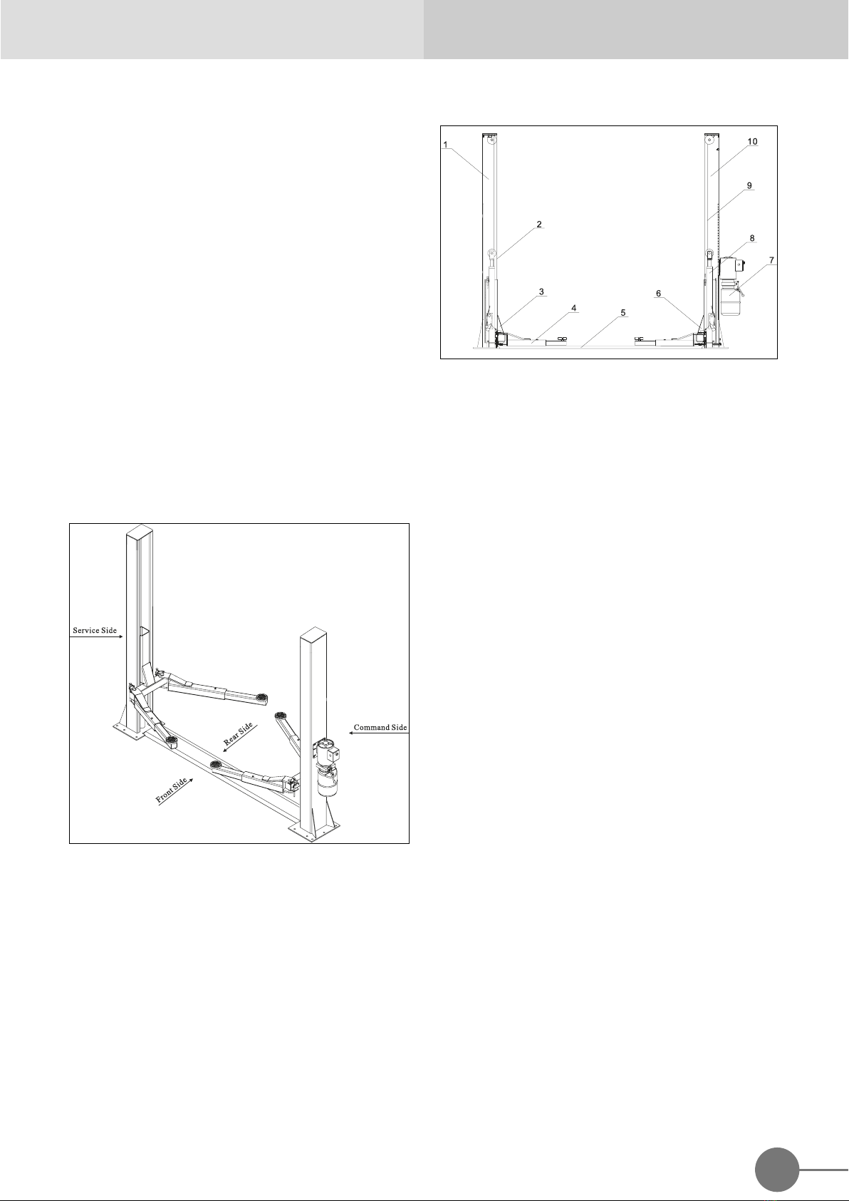
GM - 6150H 2-POST LIFT
Chapter 3 SAFETY
It is vital to read this chapter of the manual carefully
and from beginning to end as it contains important
information regarding the risks that the operator and
the maintenance fitter may be exposed to in the
eventuality that the lift is used incorrectly.
The following text contains clear explanations
regarding certain situations of risk or danger that
may arise during the operation or maintenance of
the lift, the safety devices installed and the correct
use of such systems, residual risks and operative
procedures to use (general and specific precautions
to eliminate potential hazards).
WARNING
Lift is designed and built to lift vehicles and hold
them in the elevated position in a closed workshop.
All other uses are unauthorized; in particular, the lift
is not suitable for:
◆ Washing and respire work;
◆ Creating raised platforms or lifting personnel;
◆ Use as a makeshift press for crushing purpose;
◆ Use as goods lift
◆ Use as a jack for lifting vehicles or changing
wheels.
THE MANUFACTURE DISCLAIMS ALL LIABILITY
FOR INJURY TO PERSONS OR DAMAGE TO
VEHICLES AND OTHER PCABLERTY CAUSED
BY THE INCORRECT AND UNAUTHORISED USE
OF THE LIFT.
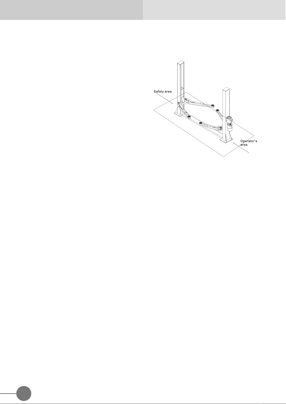
During lift and descent movements, the operator
must remain in the command station as defined in
figure 8. The presence of persons inside the danger
zone indicated in the same figure is strictly
prohibited. The presence of persons beneath the
vehicle during operations is permitted only when the
vehicle is parked in the elevated position.
DO NOT USE THE LIFT WITHOUT PROTECTION
DEVICES OR WITH THE PROTECTION DEVICES
INHIBITED. FAILURE TO COMPLY WITH THESE
REGULATIONS CAN CAUSE SERIOUS INJURY
TO PERSONS, AND IRREPERABLE DAMAGE TO
THE LIFT AND THE VEHICLE BEING LIFTED.
Fig. 10 Working Area
3.1 GENERAL PRECAUTIONS
The operator and the maintenance fitter are required
to observe the prescriptions of accident prevention
legislation in force in the country of installation of the
lift.
Furthermore, the operator and the maintenance fitter
must:
◆ Always work in the scheduled working area as
shown in the manual;
◆ Never remove or deactivate the guards and
mechanical, electrical, or other types of safety
devices;
◆ Read the safety notices affixed to the machine
and the safety information in this manual.
In the manual all safety notices are shown as
follows:
DANGER: indicates imminent danger that can result
in serious injury or death.
WARNING: indicates situations and/or types of
maneuvers that are unsafe and can cause injuries of
various degrees or death.