8 D5014 - SIL 3 Repeater Power Supply G.M. International ISM0103-3
D5014 series are isolated Intrinsically Safe Associated Apparatus installed into standard EN50022 T35 DIN-Rail located in Safe Area or Zone 2, Group IIC, Temperature T4,
Hazardous Area (according to EN/IEC60079-15) within the specified operating temperature limits Tamb –40 to +70 °C, and connected to equipment with a maximum limit for
AC power supply Um of 250 Vrms.
Not to be connected to control equipment that uses or generates more than 250 Vrms or Vdc with respect to earth ground.
D5014 series must be installed, operated and maintained only by qualified personnel, in accordance to the relevant national/international installation standards (e.g. IEC/EN60079-14
Electrical apparatus for explosive gas atmospheres - Part 14: Electrical installations in hazardous areas (other than mines)), following the established installation rules, particular care
shall be given to segregation and clear identification of I.S. conductors from non I.S. ones.
De-energize power source (turn off power supply voltage) before plug or unplug the terminal blocks when installed in Hazardous Area or unless area is known to be nonhazardous.
Warning: substitution of components may impair Intrinsic Safety and suitability for Zone 2.
Explosion Hazard: to prevent ignition of flammable or combustible atmospheres, disconnect power before servicing or unless area is known to be nonhazardous.
Failure to properly installation or use of the equipment may risk to damage the unit or severe personal injury.
The unit cannot be repaired by the end user and must be returned to the manufacturer or his authorized representative.
Any unauthorized modification must be avoided.
Warning
Operation
D5014 provides fully floating DC supply for energizing 2 wires 4-20 mA transmitters, or separately powered 3, 4 wires, 0/4-20 mA transmitters located in Hazardous Area,
and repeats and converts the current to a 0/4-20 mA or 0/1-5 V floating output signal to drive a Safe Area load.
The circuit allows bi-directional communication signal for smart transmitters, a “POWER ON” green led for each channel lits when input power is present.
Installation
D5014 series are repeater power supply hart compatible housed in a plastic enclosure suitable for installation on T35 DIN-Rail according to EN50022, with or without Power Bus or
on customized Termination Board.
D5014 unit can be mounted with any orientation over the entire ambient temperature range.
Electrical connection of conductors up to 2.5 mm² are accommodated by polarized plug-in removable screw terminal blocks which can be plugged in/out into a powered unit without
suffering or causing any damage (for Zone 2 installations check the area to be nonhazardous before servicing).
The wiring cables have to be proportionate in base to the current and the length of the cable.
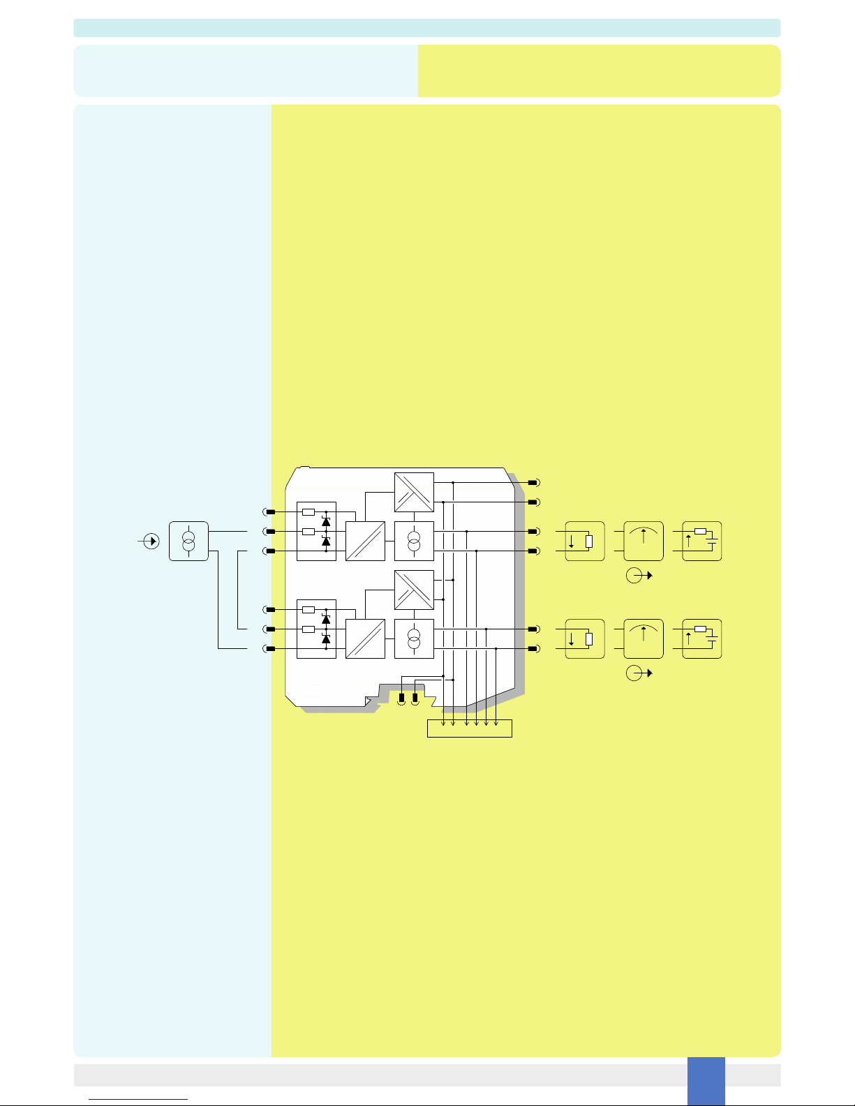
On the section “Function Diagram” and enclosure side a block diagram identifies all connections.
Identify the number of channels of the specific card (e.g. D5014S is a single channel model and D5014D is a dual channel model), the function and location of each connection terminal
using the wiring diagram on the corresponding section, as an example:
Connect 24 Vdc power supply positive at terminal “5” and negative at terminal “6”.
For Model D5014S connect positive output of channel 1 at terminal “1” and negative output at “2”.
For Model D5014D in addition to channel 1 connections above, connect positive output of channel 2 at terminal “3” and negative output at “4”.
For Model D5014S, in case of a 2 wires Transmitter, connect the wires at terminal “7” for positive and “8” for negative.
For separately powered Transmitters connect input signal at terminal “8” for positive and “11” for negative.
For Model D5014D in addition to channel 1 connections above, connect terminal “9” for positive and “10” for negative on channel 2.
Connect input signal from separately powered Transmitters at terminals “10” for positive and “12” for negative on channel 2.
Intrinsically Safe conductors must be identified and segregated from non I.S. and wired in accordance to the relevant national/international installation standards (e.g. EN/IEC60079-14
Electrical apparatus for explosive gas atmospheres - Part 14: Electrical installations in hazardous areas (other than mines)), make sure that conductors are well isolated from each other
and do not produce any unintentional connection.
The enclosure provides, according to EN60529, an IP20 minimum degree of mechanical protection (or similar to NEMA Standard 250 type 1) for indoor installation, outdoor installation
requires an additional enclosure with higher degree of protection (i.e. IP54 to IP65 or NEMA type 12-13) consistent with the effective operating environment of the specific installation.
Units must be protected against dirt, dust, extreme mechanical (e.g. vibration, impact and shock) and thermal stress, and casual contacts.
If enclosure needs to be cleaned use only a cloth lightly moistened by a mixture of detergent in water.
Electrostatic Hazard: to avoid electrostatic hazard, the enclosure of D5014 must be cleaned only with a damp or antistatic cloth.
Any penetration of cleaning liquid must be avoided to prevent damage to the unit. Any unauthorized card modification must be avoided.
According to EN61010, D5014 series must be connected to SELV or SELV-E supplies.
Start-up
Before powering the unit check that all wires are properly connected, particularly supply conductors and their polarity, input and output wires, also check that Intrinsically Safe conductors
and cable trays are segregated (no direct contacts with other non I.S. conductors) and identified either by color coding, preferably blue, or by marking.
Check conductors for exposed wires that could touch each other causing dangerous unwanted shorts. Turn on power, the “power on” green leds must be lit, for 2 wires transmitter
connection the supply voltage on each channel must be 14.5 V, output signal should be corresponding to the input from the transmitter. If possible change the transmitter output and
check the corresponding Safe Area output.